Electronic architecture for air coupled ultrasonic
pulse-echo range finding with application to security and surface
profile imaging
SONBUL, Omar and KALASHNIKOV, Alexander
<http://orcid.org/0000-0003-1431-3836>
Available from Sheffield Hallam University Research Archive (SHURA) at:
http://shura.shu.ac.uk/12088/
This document is the author deposited version. You are advised to consult the
publisher's version if you wish to cite from it.
Published version
SONBUL, Omar and KALASHNIKOV, Alexander (2014). Electronic architecture for
air coupled ultrasonic pulse-echo range finding with application to security and
surface profile imaging. Universal Journal of Electrical and Electronic Engineering, 2
(3), 105-111.
Copyright and re-use policy
See
http://shura.shu.ac.uk/information.html
Sheffield Hallam University Research Archive
Electronic Architecture for Air Coupled Ultrasonic
Pulse-Echo Range Finding with Application to Security
and Surface Profile Imaging
O.Sonbul
1, A.N.Kalashnikov
2,*1College of Computer & Information Systems, Umm Al-Qura University, P.O. Box: 715, Makkah 21955, Saudi Arabia 2
Department of Electrical and Electronic Engineering, Nottingham University, Nottingham, NG9 7EB, United Kingdom *Corresponding Author: alexander.kalashnikov@nottingham.ac.uk
Copyright © 2014 Horizon Research Publishing All rights reserved.
Abstract
Ultrasonic range finding instruments are utilized, e.g., for measuring liquid levels and distance to parking obstacles. However, instruments designed using the conventional electronic architectures to drive the ultrasonic transmitters cannot provide an operating range beyond a few meters for a flat solid wall with normal incidence when powered by a low voltage battery. This both limits the applicability of the existing instruments and makes it difficult to demonstrate their feasibility for new applications. The architecture described here combines a DC/DC boost converter with semiconductor switches, enabling a scalable increase in the operating range for both pulse-echo and pitch-catch modes of operation. It was fully prototyped and successfully tested for novel applications involving ultrasonic range finders, specifically intrusion detection and surface profile imaging. The limitations of the profile sensing device are rather restrictive as it only operates at the incidence angles below 18°, but this device can be developed further. The developed security system was found to be quite practical in its present state.Keywords
Ultrasonic Instrumentation, Airborne Ultrasound, Range Finding, Ultrasonic Driver, Profile Measurements, Intrusion Detection1. Introduction: Conventional
Applications of Air Ultrasonic Range
Finders and Their Architectures
Ultrasonic range-finding instruments have been used in industrial applications as liquid level meters [1], proximity sensors [2], and construction and surveying aids. Motorists use them as parking sensors [3], and robotics enthusiasts utilize them for robot navigation [4]. These devices employ either one or two transducers for operation in the pulse-echo or pitch-catch mode, respectively. The transmitting
transducer is connected to the driver and radiates ultrasonic waves that, after bouncing back from the target, are sensed by the receiving transducer and then amplified to a level sufficient for detection of the echo. Pulse-echo range finders may additionally include a duplexer that connects the single transducer to the driver or to the amplifier during the transmit and receive stages, respectively. The measured time difference between the excitation and reception of the echo (time of flight, TOF) determines the distance to the target. The pressure produced by the ultrasonic transmitter hence the operating range of the instrument is proportional to the root mean square (RMS) voltage applied to it.
[image:2.595.317.549.590.673.2]In addition to a.m. transducers and electronics, ultrasonic range-finding modules also include a microcontroller that switches between the operating stages as appropriate, defines the excitation waveform, and reports the measured TOF using some defined interface. As the excitation current for an ultrasonic transducer is rather low, a microcontroller’s pin can drive the ultrasonic transmitter directly (Fig. 1a). During half of the excitation time, the pin stays low; thus, the RMS voltage applied to the transducer equals Vdd/2. If two microcontroller’s pins connected to the transmitter alternate at the same time (Fig. 1b), the RMS excitation voltage doubles to Vdd, which is typically no more than 3.3-5 V.
Figure 1. Conventional architectures to drive an ultrasonic transmitter(GPO-General purpose output pin of the microcontroller)
106 Electronic Architecture for Air Coupled Ultrasonic Pulse-Echo Range Finding with Application to Security and Surface Profile Imaging
architecture increases the RMS excitation voltage to 2Vdd,
but the increase cannot be scaled further.
Further increases of the RMS excitation voltage can be achieved using either an inductor (Fig. 1c) or a transformer that form a resonant circuit together with the piezoelectric transducer at the resonant frequency of the latter. Higher quality factors result in a higher RMS excitation voltage, but also increase the rise and ringing times. A longer rise time leads to overestimation of the TOF, reducing the measurement accuracy, whilst longer ringing increases the minimal measurable distance to the target. This is why this architecture does not seem to be very popular in instruments that require a decent amount of accuracy.
Above, we have considered architectures for the ultrasonic transmitter driver only. Complete instruments also require amplifier, and optionally, duplexer circuitry. Some of these instruments are available commercially as modules or complete development boards (e.g., [5]).
The existing architectures considered above cannot achieve long operating ranges when associated devices are powered from an inexpensive sub–10 V battery. The resulting low sensitivity not only limits the applicability of the existing instruments, but also makes new applications of ultrasonic range finders (e.g., in location systems [6-8] and in some other miscellaneous devices [9-12]) either of a limited use or even unfeasible at all. For example, descriptions of many instruments and modules refer to their operating range of a few meters without mentioning that this is only achievable for a flat solid wall at normal incidence. Smaller curvy objects, e.g., people, can only be detected in a much shorter range. Additionally, conventional architectures can be complicated to implement in the pulse-echo mode of operation.
In this paper, we present a novel electronic architecture that enables the range of ultrasonic range finders to be extended several times using inexpensive components. The architecture combines a DC/DC boost converter with semiconductor switches and is fully compatible with both the pulse-echo and pitch-catch modes. It was successfully prototyped and enabled two novel applications of ultrasonic range finders: intrusion detection and surface profile imaging.
2. Application of DC/DC Converter and
Semiconductor Switches to Extend the
Operating Range of Air Ultrasonic
Devices
The proposed architecture combines a DC/DC boost converter with an H bridge, increasing the RMS voltage applied to the transducer several times compared to the power supply voltage.
H bridges are commonly used in power electronics to drive DC motors [13]. They usually include a special integrated circuit that prevents a shut through (having both
switches in the same shoulder on) and four power field effect transistors acting as switches, which handle high transient and operating currents. Most common piezoelectric ultrasonic transducers act as capacitors of typically a few nF, which do not require high currents to operate. Some semiconductor switches can be controlled from a microcontroller and withstand tens of volts; these can be used in an H bridge to drive an ultrasonic transducer. Here, we used DG419 single-pole, double-throw semiconductor switches with an operating voltage up to 44 V.
The block diagram of the considered architecture is presented in Fig. 2.
Figure 2. Use of a DC/Dc converter and semiconductor switches to increase the RMS voltage applied to the transducer
[image:3.595.317.542.230.322.2]Switches S1 and S3 alternate during the transmission, connecting the electrodes of the transducer to opposite rails of the DC/DC converter. Switch S2 connects the transducer to the receive circuit, enabling the pulse-echo mode of operation. We found it useful to discharge the transducer before entering the receive mode in order to contain its ringing. The state of all the switches during different phases of operation is presented in Table 1.
Table 1. Positions of the semiconductor switches in fig.1 at the different phases of the operation
Phase of operation S1 S2 S3 DC/DC
enable
Transmit Pin A high Up Up Down Enable
Pin A low Down Up Up
Discharge Down Up Down
Disable
Receive Down Down
Does not matter
Resistor R1 limits the recharge current through the switches when they alternate:
max / 2 1 I V
R = DC DC , (1)
where VDC/DCis the output voltage of the converter, Imax is the
current rating for the switches.
DC/DC boost converters [14] can increase the battery voltage to tens of volts in one stage. We found it essential to employ an integrated converter with an inhibit (enable) pin because of the pulse noise generated by the converter. This noise was picked up by the receive circuit despite various decoupling means applied. In particular, LT3467A was used
that was placed at the output of the DC/DC converter was charged to its full output in 18 ms. The accumulated charge was enough to produce over 3000 pulses before the voltage decreased to the power supply level. Therefore, the intermittent operation of the DC/DC converter did not delay the operation of the range finder. The number of pulses applied to the transducer was varied in order to achieve the best compromise between the amplitude of the echo and the duration of the dead zone when the echo cannot be received due to the ringing of the transducer. Five subsequent alterations for a single excitation were selected based on the experimental data.
The architecture was implemented as a part of a standalone ultrasonic module (SUM), which also included a controllable gain amplifier (30-60 dB, 53 dB gain was used throughout the experiments reported below), a 40 kHz band pass filter, a wireless communication module, and a microcontroller circuit (Fig. 3).
Figure 3. The assembled SUM ( 1 – DC/DC converter; 2 – semiconductor switches; 3 – controllable gain amplifier; 4 – band pass filter; 5 – wireless communication module; 6 – microcontroller circuit)
The output signal of the band pass filter was digitized by the internal analog-to-digital converter of the microcontroller and compared to the threshold level (Fig. 4).
This level was set to five times the noise’s standard deviation below and above the base line. The range to the target was calculated from the time of flight:
2 ) ,
( ×τ
=ct h
r , (2)
where c(t,h) is the ultrasound velocity, t is temperature, and h is humidity. This velocity was determined in the experiments reported below for measured t and h using reference tables [15]. If the amplitude of the echo decreased due to the limited area of the target exposed to the transducer’s beam or the
[image:4.595.317.550.120.291.2]beam’s non-normal angle of incidence, then the measured time of flight would move rightward on Fig. 4, leading to overestimates of the distance to the target.
Figure 4. A typical waveform at the output of the band pass filter
3. Estimation of Surface Profiles Using
an Ultrasonic Array
[image:4.595.64.293.296.535.2]The developed SUM was used together with a controllable ultrasonic array for measurement of profiles of bulk materials [16]. The array was controlled from the SUM, and this setup was capable of sensing profiles of rectangular boxes suitable for 3D reconstruction with reasonable accuracy. The measurement uncertainty was not established because the errors depended on many factors that were difficult to quantify (e.g., rigidness and flatness of the test boxes, sensitivity of individual transducers in the pulse echo mode, etc). Here we discuss additional experimental results that enable assessment of uncertainty via the observed scatter.
[image:4.595.318.551.606.750.2]108 Electronic Architecture for Air Coupled Ultrasonic Pulse-Echo Range Finding with Application to Security and Surface Profile Imaging
Figure 5. Profile measurement of two boxes with different heights taken at 18 different profiles combined
The presented experimental data exhibited higher scatter at the edges of the boxes. This was attributed to variability in the area of the boxes’ top surfaces exposed to the beam of ultrasonic transducers located close to the edges. The amplitude of the echo, and thus the moment when the latter crossed the threshold, would depend on the a.m. area, leading to overestimates of the TOF when the area became smaller. This assertion was verified by measuring profiles of a wooden sheet that was tilted towards the horizon at different angles (Fig. 6). The results confirmed that after about 15° tilt, the recorded profiles started to present a horizontal line, most likely because of the reduced echo amplitude.
[image:5.595.64.295.78.209.2]The performance of the ultrasonic profile measurement instrument was further tested using a heap of sand whose photograph is shown in Fig. 7a. The assumed trapezoidal profile (Fig. 7b) featured a calculated angle of 29° that was compatible with the range reported in [17] for sand and exceeded the maximum operating angle for the instrument estimated above. The results for 30 profiles confirmed both the scatter range of ±2 cm and difficulty in measuring slopes angled at more than 15° (Fig. 7c).
Figure 6. Profile measurements of a flat wooden sheet taken tilted to the horizon at different angles ( a - 12°; b – 15°; c – 18° )
C
Figure 7. A photograph of the heap of sand (a), its assumed profile (b) and measurement results taken at 30 different cross sections combined (c)
Finally, a ball presenting incidence angles from 0° to 90° to the horizon from above was profiled using the instrument. We expected that the width of the profile visible to the
[image:5.595.316.546.235.654.2]The established upper limit of about 15° tilt seems rather restrictive for most applications. We envisage that it could be extended by using several transducers in the receive mode, which might pick up the beam reflected by the profile away from the transmitter. Verification of this assertion would require redesign of both the SUM and array, and has not yet been attempted. Another possibility would be to apply synchronous averaging [18] in order to reduce the standard deviation of the noise to enable lower threshold levels.
Figure 8. Profile of a ball and associated measurement results
4. Intrusion detection using the SUM
Ultrasonic devices have been used in some security systems for motion sensing in a confined space based on the Doppler effect, and as proximity sensors. Both of these uses have been superseded by passive infrared (PIR) sensors and line-of-sight optoelectronic transmitter-receiver pairs, respectively. We assume that ultrasonic range finders can be useful for security applications because they can be used to detect intrusion from one side only, unlike line-of-sight optopairs, and easily ignore intrusions occurring beyond the set distance, unlike PIR sensors. These properties seem valuable for public display events or venues, as they allow an unobtrusive view of the exhibits but can detect a visitor coming too close. The developed SUM was considered suitable for this application because it could be battery powered and report intrusion wirelessly, operating as a part of a network of easily installable devices.
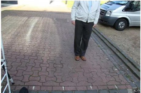
The instrumentation used for outdoor intrusion detection experiments is shown in Fig. 9. The ultrasonic transducer was securely attached to a tripod and connected to the SUM. The SUM was powered from a laptop that also recorded the results received using a matching wireless adaptor. A temperature and humidity sensor measured environmental conditions that affected the ultrasound velocity. A volunteer was placed at every node of the two-dimensional grid with a step of 0.5 m (Fig. 10).
For this application, the accuracy of range finding is of secondary importance compared to the hit (an intruder is present and detected) and false alarm (an intruder is absent but her/his presence is reported) probabilities. With the detection threshold set as discussed above, we did not
observe any false alarms for a considerable time. The probability of a hit was estimated by performing 500 range findings and counting the number of times when the echo crossed the threshold boundaries N as follows:
500
N
phit = . (3)
[image:6.595.67.296.191.327.2]The probability of a hit remained quite consistent over various environmental conditions, namely temperature in the range of 10–15°C and relative humidity in the range of 46–71%.
Figure 9. Instrumentation for measuring the intrusion detection probability
Figure 10. Outdoor arrangement for measurement of the intrusion detection probability. The volunteer was placed at all the nodes of the grid with the step of 0.5m.
[image:6.595.318.544.213.378.2] [image:6.595.317.548.418.571.2]110 Electronic Architecture for Air Coupled Ultrasonic Pulse-Echo Range Finding with Application to Security and Surface Profile Imaging
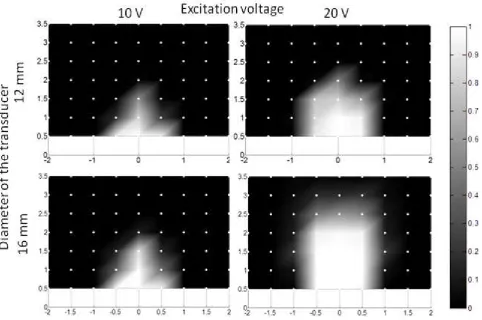
Figure 11. Detection probabilities for different transducers and excitation voltages measured at the nodes shown by white dots and interpolated to the whole area of interest (the scale for the probabilities is shown on the right)
5. Conclusions
The described electronic architecture featuring a combination of a DC/DC boost converter and semiconductor switches for the excitation of an air coupled ultrasonic transducer was found to be robust in extending the operating range of pulse-echo ultrasonic range finders. It was essential to limit the current through the switches when they alternated in order to prevent their damage, and to disable the converter at the receive phase of operation.
This architecture was implemented with discrete components but it seems realizable using an application-specific integrated circuit (ASIC) that would reduce the component count, size, and weight of the associated instruments. Commercially available examples of similar ASICs include ultrasonic sonar ranging IC PW0268, piezoelectric horn driver RE46C100, and the recently released ultrasonic sensor signal conditioner PGA-450, which includes an on-chip microcontroller, or piezo haptic driver with integrated boost converter DRV8662. Such an ASIC would require only a few external components like an inductor for the DC/DC boost converter and decoupling capacitors.
The described architecture extends the operating range of ultrasonic range finders several times. This not only widens the applicability of existing devices but also enables new applications. Two of these applications (namely intrusion
detection and profile sensing) were fully prototyped successfully. The limitations of the profile-sensing device are rather restrictive, but this device can be developed further, as discussed. The developed security system was found to be quite practical in its present state.
REFERENCES
[1] Ultrasonic level sensors, http://en.wikipedia.org/wiki/Level_ sensor#Ultrasonic [Sept 28, 2013].
[2] X.Li, R.Wu, M.Sheplak and J.Li, "Multifrequency CW-based time-delay estimation for proximity ultrasonic sensors," Radar, Sonar and Navigation, IEE Proc., vol.149, no.2, pp.53-59, Apr 2002.
[3] T.Schlegl, T.Bretterklieber, M.Neumayer and H.Zangl, "Combined Capacitive and Ultrasonic Distance Measurement for Automotive Applications," Sensors J., IEEE , vol.11, no.11, pp.2636-2642, Nov. 2011.
[4] A.M.Sabatini and A.Rocchi, "Sampled baseband correlators for in-air ultrasonic rangefinders," Industrial Electronics, IEEE Trans., vol.45, no.2, pp.341-350, Apr 1998.
[6] V.Agarwal, N.V. Murali, C.Chandramouli, "A Cost-Effective Ultrasonic Sensor-Based Driver-Assistance System for Congested Traffic Conditions," Intelligent Transportation Systems, IEEE Trans., vol.10, no.3, pp.486-498, Sept. 2009.
[7] M.M.Saad, C.J.Bleakley, T.Ballal and S.Dobson, "High-Accuracy Reference-Free Ultrasonic Location Estimation," Instrumentation and Measurement, IEEE Trans., vol.61, no.6, pp.1561-1570, June 2012.
[8] J.Reijniers and H. Peremans, "Biomimetic Sonar System Performing Spectrum-Based Localization," Robotics, IEEE Trans., vol.23, no.6, pp.1151-1159, Dec. 2007.
[9] Se Dong Min, Jin Kwon Kim, Hang Sik Shin, Yong Hyeon Yun, Chung Keun Lee and Myoungho Lee, "Noncontact Respiration Rate Measurement System Using an Ultrasonic Proximity Sensor," Sensors J., IEEE , vol.10, no.11, pp.1732-1739, Nov. 2010.
[10] P.McVittie, and L.Atlas, "Air-coupled ultrasound time-of-flight estimation for shipping container cargo verification," Acoustics, Speech and Signal Processing, 2008.
ICASSP 2008. IEEE Int. Conf., pp.1797-1800, March 31
2008-April 4 2008.
[11] R.Kazys, L.Mazeika, R.Sliteris and A.Voleisis, "Online Profiling of Nonplanar Objects by High-Resolution Air-Coupled Ultrasonic Distance Measurements,"
Instrumentation and Measurement, IEEE Trans., vol.56, no.5, pp.1825-1830, Oct. 2007.
[12] Tat Hean Gan and D.A.Hutchins, "Air-coupled ultrasonic tomographic imaging of high-temperature flames," Ultrasonics, Ferroelectrics and Frequency Control, IEEE Trans., vol.50, no.9, pp.1214-1218, Sept. 2003.
[13] H bridge, http://en.wikipedia.org/wiki/H_bridge [Sept 28, 2013].
[14] Boost converter, http://en.wikipedia.org/wiki/Boost_convert er [Sept 28, 2013].
[15] G. Kaye and T. Laby, Tables of physical and chemical constants and some mathematical functions, 15th ed. London: Longman, 1986.
[16] O.Sonbul, P.Popejoy and A.N.Kalashnikov, "Ultrasonic Sensor Array for Remote Sensing of Profiles of Bulk Materials", Proc. 2012 IEEE Int. Instr. Measur. Techn. Conf., 13-16 May, Graz, Austria, pp.1794-1797.
[17] Angle of repose, http://en.wikipedia.org/wiki/Angle_of_repo se [Sept 28, 2013].