GUARDIANS final report
PENDERS, Jacques <http://orcid.org/0000-0002-6049-508X>
Available from Sheffield Hallam University Research Archive (SHURA) at:
http://shura.shu.ac.uk/2340/
This document is the author deposited version. You are advised to consult the
publisher's version if you wish to cite from it.
Published version
PENDERS, Jacques (2010). GUARDIANS final report. Project Report. Sheffield
Hallam University. (Unpublished)
Copyright and re-use policy
See
http://shura.shu.ac.uk/information.html
Guardians
Final Report
Jacques Penders, editor
March 18, 2010
Abstract
Emergencies in industrial warehouses are a major concern for fire fighters. The large dimensions together with the development of dense smoke that drastically reduces visibility, represent major challenges. The
Guardiansrobot swarm is designed to assist fire fighters in searching a
large warehouse. In this report we discuss the technology developed for a swarm of robots searching and assisting fire fighters. We explain the swarming algorithms which provide the functionality by which the robots react to and follow humans while no communication is required. Next we discuss the wireless communication system, which is a so-called mobile ad-hoc network. The communication network provides also one of the means to locate the robots and humans. Thus the robot swarm is able to locate itself and provide guidance information to the humans. Together with the fire fighters we explored how the robot swarm should feed information back to the human fire fighter. We have designed and experimented with interfaces for presenting swarm based information to human beings.
CONTENTS CONTENTS
Contents
1 Preface, Remarks by Fire Fighters 3
2 Introduction 5
3 Warehouse search 6
3.1 Navigating in smoke . . . 7
3.2 Radio contact . . . 9
4 Robot Platforms and Sensors 9 4.1 Adapted off-the-shelf platforms . . . 10
4.2 Purpose built platforms . . . 10
4.3 Chemical Sensors . . . 13
4.3.1 Array of QCM and MOS sensors . . . 13
5 Swarm robotics 17 5.1 Brief overview of the state of the art . . . 17
5.2 Swarming in theGuardiansenvironment . . . 18
6 Non-communicative swarming 20 6.1 Control model . . . 21
6.2 Human-swarm formations . . . 21
6.3 Olfactory Navigation . . . 24
6.4 Sensor based exploration . . . 26
7 Networking 29 7.1 Communication Infrastructure . . . 29
7.2 Topology and routing . . . 32
7.3 Novelty of the communication system . . . 34
7.4 Recovery from failures of individual nodes . . . 35
7.5 Localisation and Mapping . . . 40
8 Assistive Swarming 47
9 Base station, baseline concept 50
10 Conclusions and future work 54
1 PREFACE, REMARKS BY FIRE FIGHTERS
1
Preface, Remarks by Fire Fighters
In the course of the Guardiansproject we have cooperated with South York-shire Fire and Rescue (they are project partners) as well as with several other fire brigades. South Yorkshire Fire and Rescue were involved from the defini-tion and proposal phase of the project as end-user advisor. They have organ-ised a one day fire training at the kick-off of theGuardiansandViewFinder
projects. The project members experienced this as very useful as it shaped their perception of what what a rescue operation involves. In return, the final demon-strations of the Guardians and ViewFinder were organised at the training station of South Yorkshire Fire and Rescue. Below are the major comments received from fire fighters reflecting on the research work.
The overall comment of South Yorkshire Fire and Rescue about their involvement in the Guardians as well as the ViewFinder projects is the following. As a Fire Brigade we do not have the means to be at the forefront of science and technology developments. However, we are looking at technology to help us improve our service. Improvements can be in risk assessment as well as direct support for the rescue operation. Being involved in these projects has made our officers better aware of available and up-coming technologies. The final demonstrations at our premises certainly got more of our staff involved to look at what was available.
Comments on the technology. Breathing Apparatus wearers progress at crawling speed. A group of robots guiding the fire fighters could speed up the search. Robots are considerably smaller then a human being thus their sensors operate closer to the floor where the smoke is less dense and temperatures are lower.
Despite advances in communication technology, the problem of maintaining radio contact in indoor incidents is still not solved; the ad hoc mobile network provides is a very interesting solution that seems to tackle the main problem of by passing obstacles in the radio spectrum. Such a network would fit in very well and enhance the communication system applied in the new Command Support Vehicle developed by South Yorkshire Fire and Rescue. The main idea behind this vehicle is to collect from and distribute to the officers (on site as well as off site) relevant and up-to-date information about the incident.
The base station developed would also be very well situated in this vehicle, and add to the info available during an incident.
Risk assessments relating to the possible presence of Hazardous Chemicals are very time consuming, robots with a mobile detection unit would certainly speed this up. The QCM chemical sensors has been designed for in-situ detection of low as well as high concentration of VOCs and toxic gases. Applied on a robot we can take more risks and contamination and in particular decontamination would not be as a big an issue as it is related to human beings.
Pictures of the early stage of an incident are very useful for forensic inves-tigations and debriefings; however our staff is focussed on the rescue operation. Robots could simply store their data for post-incident off-line review.
1 PREFACE, REMARKS BY FIRE FIGHTERS
• The registration of on-site Chemicals is not uniform over the EU countries, several countries do lack good registration.
• An overall requirements list and possibly a set of specifications for inter-vention and rescue robots would be very useful.
2 INTRODUCTION
2
Introduction
TheGuardians1(Group of Unmanned Assistant Robots Deployed In
Aggrega-tive Navigation by Scent) project is an FP6, EU funded, project developing a swarm of autonomous robots. Swarm robotics is a relatively new area of research and very diverse approaches are reported in the literature. However descrip-tions of everyday applicadescrip-tions are as yet relatively rare. When we approached South Yorkshire Fire and Rescue (UK) to enquire about the applicability of our swarm of robots, they pointed out that industrial warehouses in the emergency of a fire are a major concern to them. Searching for victims is dangerous be-cause of the combination of the enormous dimensions of the warehouses and the expected low visibility when smoke develops. The searching of an industrial warehouse in smoke was subsequently made the central application scenario of theGuardiansproject.
A major role of the robot swarm in this scenario is to support human beings searching the warehouse by enhancing the human’s navigation. Since no heavy physical task is assigned to the robots, the swarm may consist of small and even mini-robots. Whereas locomotion is not a problem, the smoke poses a problem for human beings as well as for robots. The low visibility causes a number of related problems: it hampers navigation as the sight on landmarks is lost and subsequently localisation and mapping become problematic. Radio contact partially relieves these problems, however as we will discuss a warehouse is full of obstacles in the radio spectrum.
Support for humans is a final aim for the Guardians swarm of robots. However, whereas swarm robotics is a new but developing field, the development of interfaces for humans to interact with a group or swarm of robots is in its infancy. In the Guardians project the interaction of the human with the robot swarm is separated from the feedback that the swarm provides to the human. Human beings are autonomous members of the group and are free to behave as they wish. The feedback of the robot group to the humans consists in guidance and navigation instructions, on the basis of which the humans may or may not change their behaviour. The robots react similarly to the actions of the humans as they do to other group members. Thus, the behaviour of the humans influences the robot group, however the humans do not directly instruct any robot. Since theGuardiansconsortium first published these ideas [53, 55] several papers have appeared. However, only a few papers respect and take advantage of the autonomy of the robots: similar to our approach Hashimoto et al. [29] have a human being participating as a swarm member, while Bashyal and Venayagamoorthy [10] let a human remotely control one of the robots in the swarm.
The theme of this paper is the realisation of a swarm or group of robots searching on its own or assisting human fire fighters. Obviously, the swarm becomes only useful when the swarms’ navigation and communication problems are solved. We explain the swarming techniques which we apply to deal with the
1
3 WAREHOUSE SEARCH
problems and discuss the results of our experiments with real robots. First, in section 3 we discuss the application scenario and draw some early conclusions which are guiding the further developments. Section 4 briefly describes the robot applied; adapted off-the-shelf platforms as well as purpose built robots.
Section 5 provides a brief overview of swarm robotics and the conditions under which theGuardiansrobot swarm will be applied. Section 6 discusses the swarm technology applied to make the swarm accompany human beings. This is the technology that also enables humans to influence the robot group. The wireless communication system plays an essential role in the navigation of the human and the robot group. In section 7 we discuss the communication network as well as localisation and mapping. This is also the point where the feedback from the robot group to the human has to be prepared. In section 8 we discuss the experiments with the human robot swarm interface. The main subject in this section is how the robot group feeds back to the human being. We finish in section 10 by drawing conclusions.
3
Warehouse search
Generally speaking warehouses consist of large open spaces alternating with storage areas consisting of vertical racks in which a multiplicity of materials is stored. Modern warehouses are usually single storey buildings in which stairs are not common; they can be as large as 400×200m2. Large warehouses are
divided into sections separated by fire resistant walls (that is, resistant for several hours). The typical dimensions of sections are in the order of 100×200m2. (For
convenience a section counts as a warehouse in the discussions below). The fire fighters have indicated that in the event of a fire, the fire will be confined to a certain area of the warehouse, however smoke may cover the whole warehouse. There might be some debris on the floor, but one may assume that most of the warehouse is in quite an orderly state. Thus, the ground will be easily passable; if the situation deteriorates fire fighters will not enter the building, because of the increased risk level2. For the robot swarm this implies that there are no exceptional requirements concerning the locomotion and even wheeled mini robots are suitable. Usually a map of the premises is available, however the map will show only the major constructive elements such as walls and doorways, but may not contain an interior design or contain an obsolete interior design.
When fire fighters have to enter a smoke-filled environment, they are pro-vided with breathing apparatus to provide fresh air. However, the smoke reduces visibility dramatically and human beings easily get disoriented and may get lost. Rendered without sight fire fighters can only rely on their touch and hearing senses. However these senses are also restricted. The sense of touch is restricted by clothing gear and hearing is reduced by noisy breathing apparatus.
The large scale of a warehouse, the low visibility and the time constraints render the searching of a warehouse very risky. This is underlined by tragic examples. In the warehouse fire of 1991 in Gillender Street London (UK), two fire fighters died and in the 1999 warehouse fire in Worcester (USA), six fire fighters lost their lives. And recently in November 2007 a tragedy happened in
2Firefighters will take some risk to save saveable lives; however they will not take any risk
3.1 Navigating in smoke 3 WAREHOUSE SEARCH
Warwickshire (UK), when four fire fighters were killed in a vegetable warehouse blaze.
In the Worcester case, first a crew of two fire fighters reported being lost 22 minutes into the incident; 30 minutes later, an emergency team consisting of four fire fighters got lost as well3. The Worcester warehouse was a six storey
building with largest dimensions 40×50m2, where thick black smoke developed.
(Note that this floor space is only a tenth of the floor space of a section of the modern warehouses referred to above.) The communication link was frequently interrupted and the emergency teams were not sure on which floor the first crew got lost.
The above indicates significant challenges if fire fighters are to work effec-tively with robots while searching:
• The search environment is highly oppressive for a human being:
– poor visibility due to smoke;
– poor tactile awareness due to safety-clothing and
– limited hearing due to fire fighters headgear and ambient noise.
This presents ergonomic and communicative design problems for direct human robot interaction.
• Fire fighters operate with established protocols to ensure safety and robot behaviours should complement these protocols to enhance the search and rescue tasks and not be disrupting.
• Fire fighters engaged in search and rescue are working under considerable mental and physical stress. When assisting, the swarm of robots should in general not increase the navigation related load (physical or cognitive) [36] of the human being.
3.1
Navigating in smoke
In the United Kingdom procedures are that a first team will lay-out and fix a guideline along a wall, refer to figure 1. Subsequent teams aiming towards the scene of operations follow the guideline but nevertheless they advance only at a crawling speed. We informally clocked a guideline following exercise by experienced fire fighters: they progressed 12m in about one minute. The amount of oxygen contained in the breathing apparatus suffices for about 20 minutes. Given the crawling speed, fire fighters can proceed about 240m with a full tank. Taking into account that they have to negotiate the 20 minutes of air between getting in and getting out, the maximum advance they can make is only 120m which is less than the largest dimension of the modern warehouses. Robots guiding the fire fighters could speed up the search.
Smoke obstructs perception in the visible spectrum; this is the case for the human eye as well as for most robotics sensors such as cameras (mono or stereo) but also for laser range finders (LRF) as our experiments confirmed [50]. What is perceived as smoke, consists of particles on which light is scattered. Criti-cal concentration values depend both on the particle size and on the distance
3.1 Navigating in smoke 3 WAREHOUSE SEARCH
Figure 1: Basic principle for Guideline layout in a search operation.
Figure 2: Smoke development simulation, left: the early stage where the sofa on the right catched fire; right: about 20 minutes later, thick black smoke is covering the room from the ceiling downwards.
(depth of view). Our trials with smoke, showed that the maximum range of the laser depends on the spatial and temporal distribution of the smoke, this dis-tribution is non-uniform. This can be validated with the well known simulator and simulation results from the National Institute of Standards and Technology (NIST) [41] and their comparative studies of visibility in smoke, for example in [12]. Using the NIST fire dynamics software package, we have simulated a typi-cal room environment in smoke with typitypi-cal ventilation and air-flow constraints offered within the NIST database (refer to Figure 2).
3.2 Radio contact 4 ROBOT PLATFORMS AND SENSORS
3.2
Radio contact
Besides the problems with navigating in smoke, the tragic examples discussed above also show the need for continuous and uninterrupted communication links between the crew inside and managing-crews outside. In a warehouse however, the racks form a dense lattice of metal joints, which might be packed with tins, cans or other metal based packagings. Within this metal cave, the transmission and reception of radio signals is problematic and communication connections get broken.
Applying a swarm of robots provided with radio transmitters and receivers, provides new opportunities. Having a swarm of robots allows that they can disperse over the area. While ‘radio’ obstacles might block a direct connection between all swarm members, individual robots will be within ‘the line of sight’ of some other robots and together the swarm can form a chain or mesh of robot-to-robot communication links. One or more chains may help to maintain the radio connections. However, if many robots are present in the same area, com-munication among them has to be well organized. If all robots are broadcasting at the same point in time, chaos will result: the interference between the signals will cause data losses and errors. Therefore we apply a so-called mobile ad-hoc network communication system, in which any robot may act as communication node. While the swarm advances some robots can become dedicated beacons to ensure communication coverage.
Smoke is not an obstacle for the radio signal, and in addition to the com-munication facilities, the ad-hoc network can provide position data to support localisation of the mobile robots and humans. Note that indoor localisation sys-tems like GPS are not accessible. To enhance localisation beacons are required and a suitable trade off is being sought between beacons for both communication purposes and positioning purposes.
The smoke in the warehouse may contain substantial concentrations of toxics or inflammables. The robots are provided with an artificial nose to warn for chemicals. The noses enable the robots to applyolfactory-based navigation and chemical plume detection [50]. However, we will not discuss olfactory-based navigation in this paper.
4
Robot Platforms and Sensors
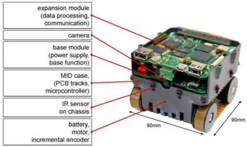
Four main robot platforms have been used for experimenting with the different aspects of theGuardians project. The off-the-shelf Khepera III (mini robot) platform of K-Team was applied for the small-scale experiments in map-building and olfactory-based navigation. The middle mid-sized platform Erratic robot was used for testing and validation of robot swarming and human robot-swarm implementations. A new mini robot called BeBot was built to aid advanced research in mobile ad-hoc communication. The real scale Guardian robot was developed within the project and is intended as the type of robot for operational implementation of the project results.
4.1 Adapted off-the-shelf platforms4 ROBOT PLATFORMS AND SENSORS
4.1
Adapted off-the-shelf platforms
Regarding the Khepera robot platform, refer to figure 3(a), its ultrasonic sen-sors were upgraded to have better results. A new toolbox for Khepera III was presented (Khepera III toolbox from EPFL) providing better access to odome-try. And the new linux Kernel 2.6 for Khepera 3 was completed and distributed. Among other features, it now supports USB cameras. As theGuardiansswarm is to be applied in smoky conditions two sets of sensors appropriate to detect gases, heat and flames was built and interfaced to the Khepera III mobile robot: the Khe-nose shown in figure 3(b) and the QCM sensors show in figure 13 and discussed in section 4.3 below.
[image:11.595.126.466.274.433.2](a) (b)
Figure 3: Khepera III robots: left mounted with a Hokuyo laser, right with the Khe-nose
For the test scenario of the human robot-swarm interaction described in section 8 the Erratic platform was used, refer to figure 4. On top of the Player/Stage software an agent-based architecture has been programmed us-ing the JADE framework. Different behaviours for fire-fighter localisation and following were performed. This work is described in section 6.
4.2
Purpose built platforms
4.2 Purpose built platforms 4 ROBOT PLATFORMS AND SENSORS
[image:12.595.127.502.137.285.2](a) (b)
Figure 4: Two experiments (a) Team of Erratic robots maintaining a formation; (b) Team of Erratic robots maintaining a flexible formation around a human being
Figure 5: BeBot miniature robot with the main hardware components
3900mAh lithium-ion accumulator.
[image:12.595.168.417.345.493.2]4.2 Purpose built platforms 4 ROBOT PLATFORMS AND SENSORS
Figure 6: The Guardian robot, provided with Ultra Sound and Laser Rage Finder
expendabilities, like IC, UART, USB, MMC/SD-card, audio, LCD and camera. The central communication device for the wireless network is HNI’s gate-way module. This mobile communication gategate-way is optimized for the mobile usage and therefore supports different techniques for energy saving. Some of these techniques are dynamic frequency and voltage scaling as well as dynamic power down of non-used hardware components. It is equipped with the new OMAP35xx processor, which delivers more than 1,200 Dhrystone MIPS at low power levels. The standard configuration supports the wireless communication standards Wi-Fi and Bluetooth. Based on a modular concept it can be equipped with additional Ethernet or NanoLoc communication. The latter communica-tion module offers distance measurement between wireless network nodes. Ad-ditionally the wired communication standards IC, SPI, UART and high speed USB allows variable expansion of the gateway. Therewith it is possible to con-nect sensors, actors, robots or computers direct with the gateway and thereby with the communication network. The gateway can be connected to any kind of robot to act as a mobile communication device. But it can also be used as static device for example to locally capture sensor data and to transmit these data to the base station. More details of the gateway device are presented in workpackage 3 description and in deliverable D.3.5.
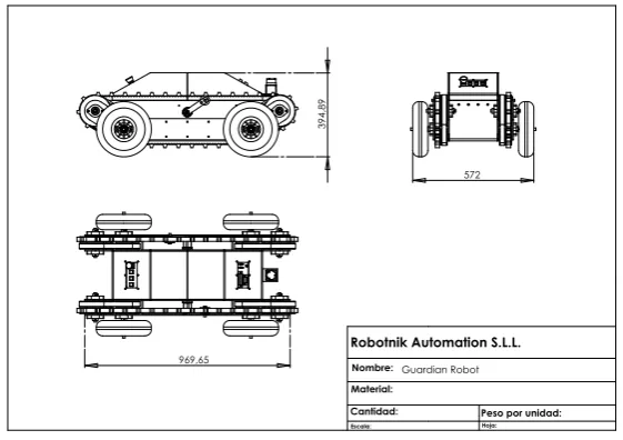
Guardian. The Guardian platform, refer to figure 6 and 7, has been devel-oped by Robotnik within the Guardiansproject. It is a medium sized robot platform of a size and scale that allows application in a real case. Main features of the mobile robot are:
• Size: 970 x 570 x 395 (L x W x H)
• Max. Speed: 1 m/s
• Weight: 110 Kg
• Max. Load: 100 Kg
4.3 Chemical Sensors 4 ROBOT PLATFORMS AND SENSORS
969,65
3
9
4
,8
9
572
Guardian Robot
Cantidad: Material:
Robotnik Automation S.L.L.
Nombre:
Escala: Hoja:
[image:14.595.156.437.128.326.2]Peso por unidad:
Figure 7: The Guardian robot, Main construction and Dimensions
Guardian robot. The Guardian robotic platform offers the possibility of testing in real user scenarios, meaning rough terrains, debris, slopes or even stairs. The Guardian robot could be applied for real assistance tasks as it provides high mobility, high speed and can carry firefighting tools. Further improvements focus on extending the capabilities for fire-fighting applications such as foam spraying and enhanced heat resistance. The robot has been tested to follow a human fire fighter using Ultra Sound sensors and a Laser Range Finder, these are described in subsection 7.5. It has also been used as part of the ad-hoc mobile communication network described in section 7, and the QCM sensors (discussed in the next section) are mounted on it as well.
4.3
Chemical Sensors
The possible presence of hazardous materials at an incident is a considerable risk factor. The Guardians project dedicated considerable work to the develop-ment of a sensor array for the detection of volatile organic chemicals (VOCs) in low and pre-explosive concentrations as well as for olfactory robotic navigation. Two types of chemical sensors are used (commercially available) Metal-oxide semiconductor (MOS) and home built quartz crystal microbalance (QCM) sen-sors. The MOS sensors are applied to detect low concentrations, while the QCM are appropriate for high concentrations. In the Khe-nose (refer to figure fig:khepera(b)) built by ISR only MOS sensors are applied. Below we describe the sensor array built by SHU, which combines both types.
4.3.1 Array of QCM and MOS sensors
4.3 Chemical Sensors 4 ROBOT PLATFORMS AND SENSORS
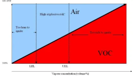
Figure 8: Graphical representation showing the flammable properties of a typical organic solvent, LEL and UEL levels.
Figure 9: Calix(4)resorcinarene with ’P’ representing the hydrocarbon tail com-position.
effective risk assessors, the chemical sensors have to detect low concentrations as well as high concentrations. In the tests we performed, low concentrations are below the LEL and the high concentrations are above the upper explosive risk level (UEL).
We developed the sensor array to detect volatile organic chemicals (VOCs) in pre-explosive concentrations; the sensors are also used for olfactory robotic navigation. The QCM (quartz crystal microbalance) sensors are built utilising quartz crystals. They are spun-coated with different thin films of amphiphilic calixarene molecules to provide an array which is the basis for pattern recog-nition. By altering the length of the hydrocarbon tail, selectivity between tar-get analytes has been achieved. Figure 9 shows the chemical structure of am-phiphilic calixarene. These QCMs start responding when the concentration is below the LEL zone, but operate most effective when the concentration gets into the explosive risk zone.
[image:15.595.228.364.319.439.2]4.3 Chemical Sensors 4 ROBOT PLATFORMS AND SENSORS
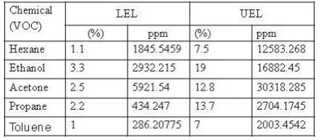
Figure 10: the LEL-High explosive risk-UEL zone for each of the VOCs.
Figure 11: LEL and UEL for five different types of analytes.
the 500ppm level but sufficient for the levels above that. Accurate detection of common VOC’s above 500ppm has been achieved, at concentrations below 500ppm a simple binary alarm system warns of a potentially hazardous leak and or explosive risk.
Figure 11 illustrates the LEL-High explosive risk-UEL zone for each of the VOCs considered in the table in figure 10.
Membrane recognition/sensor selectivityAnalysis of the experimental data shows that the best combination of QCMs for analyte recognition is the following: (i)calix[4]resorcinarenes with alkyl chains of different lengths named C15H31 and C5H11; (ii) the same calix[4]resorcinarenes with alkyl chains of C4RA-C15 and C4RA-C5,(iii)tetra-tertbutyl calix[8]arene named as C8A-ttb. Figure 12 shows a 3D plot of the three QCM sensor responses and highlights the levels of separation between the analytes which leads to the individual detection identification and quantification Acetone, Ethanol and Hexane vapours. The space between curves and curve diversity approaches the recognition code of the analytes. The ANN was built to read this VOC diversity and identify.
[image:16.595.190.399.279.454.2]4.3 Chemical Sensors 4 ROBOT PLATFORMS AND SENSORS
Figure 12: The concentration range of this recognition test is up to 40000ppm.
for Acetone, Ethanol, Propane, Toluene and Hexane were investigated many times to establish the reproducibility and stability of the coated QCMs (C4RA-C15, C4RA-C5 and C8A-TTb) for such VOCs. Some of the QCM provide high stability and a significant reproducibility. Whereas, the sensitivity of C4RA-C15 is varied between 0.006 to 0.008 for Acetone and 0.003 to 0.005 for Hexane and the sensitivity of C4RA-C5 s varied least (0.002-0.003), as shown in figure 12. This variation is still within the responding diversity of the coated QCMs and it is not affecting the recognition signal code reading. Further sensitivity codes are given in Deliverable 2.2.1.
Electronics PrototypeTwo prototype sensor arrays have been constructed consisting of QCM devices. The sensing membranes applied to the QCM have been optimized for the target analytes required. Prototype Printed Circuit Boards (PCB) has been produced and a microcontroller based data acquisition system has been developed. The sensor responses are output from the micro-controller using the RS232 interface to a PC where further data analysis and logging takes place. The first sensor array has been constructed using 8 QCM sensors; this number however was decreased later to comfort application on the mini robots. The sensing elements are separated from the driving electronics (on a different PCB) to allow controllable gas exposure within a purposely built FPGA. The QCM oscillators have been designed and fabricated in house. The QCM have been coated with a range of calixarene derivatives which provide very fast and fully reversible responses to the majority of Volatile Organic com-pounds (VOC), as we mentioned before.
A new prototype was required using less power and a small number of sensors than the prototype in stage one. This new board needs to be integrated to a small robot for gas navigation. Three QCM sensors were selected using the best combination of QCM sensors. The sensing elements are collecting the data and send it through the wireless communication to the base station for recognition analysis. Figure 13(a) shows the 3 QCM prototypes. The oscillator drivers were constructed on a separate PCB which is pluggable into the main processor board. The multi channel frequency counters and filtering were implemented using an FPGA.
5 SWARM ROBOTICS
(a) (b)
Figure 13: The Chemical Sensors (a) 3 QCM prototype; (b) Khepera robot integrated with chemical sensors.
programming interface and access to a range of data storage (SD and inter-nal flash) and communication interfaces (UART, SPI, I2C, CAN). The SHT71 temperate and relative humidity sensor has also been included on the processor board. This allows automatic compensation for either temperature or humidity if required.
For simplicity a basic UART link provided the data communication between the sensor and the Korebot. The specifications for the data format and interpre-tation of the data string are given in deliverables D2.2.1 and D2.2.3. A player driver by has also been implemented by KTEAM to receive and process the incoming data on the korebot. This prototype was interfaced and integrated to several robots. The mountings on the sensor processing PCB have been designed to directly align with the Korebot. The interface board maps the I/O on the sensor to suitable ports on the Korebot and supplies power from the Khepera base to the sensor PCB and sensor processing PCB. The complete assembled sensor mounted on the Khepera is shown in Figure 13(b).
5
Swarm robotics
5.1
Brief overview of the state of the art
5.2 Swarming in the Guardiansenvironment 5 SWARM ROBOTICS
use swarm simulations to find problem solutions.
The geometrical oriented swarm robotic approaches are relevant to our work. Due to its dimensions, a warehouse requires a large number of robots. We apply many of the same robots as a single robot cannot do much in a large warehouse. Communication with the outside might not be possible and the human being will be busy ensuring his own safety. Thus, there will be circumstances where the robots have to rely on local information while autonomous decision making is a requirement.
Initial robot swarm research has focused on centralised approaches [40, 9], aiming at motion planning [38, 39] or leader domination [15]. However, the large number of robots generate dynamic behaviour for which central control is computationally expensive and hard and also centralised motion planning is inappropriate. Recent research emphasises autonomy of the robots and applies decentralised approaches which reduce computational complexity and provide robustness to failures. Such approaches include behavioural-based robotics [8], artificial potential functions [57, 18, 27, 25, 26], virtual agents or virtual struc-tures [7, 47], probabilistic robotics [60], and others [61]. Some approaches use optimisation criteria from game theory for navigation control [64] and robot distribution or area coverage [13]. There are also works dealing with improving system performance through adaptation and learning [51, 62, 5]. Some of these works use global information while others are based on local interactions and rules. Moreover, besides bio-inspired models there is current research interest in control-theoretic approaches. Surveys on recent advances and the state of the art in swarms can be found in [16, 59, 37] and a web database on swarm robotics related literature has been compiled at swarm-robotics.org.
5.2
Swarming in the Guardians environment
The Guardians swarm is intended to support search operations. To oper-ate successfully in the warehouse scenario the robots in the swarm will have to deal with several quite different situations. In situations where there is no communication link with other robots, a robot has to navigate on its own sen-sor inputs. When other robots are within the sensen-sor range but communication is not possible, still certain group behaviours can be achieved: we call these the non-communicative behaviours. The robot swarm brings its own wireless communication network into the warehouse and while the swarm is advancing the communication network is to be extended. We classify the behaviours that are focussed on maintaining and expanding the communication network as net-working behaviours. When communication is available and the swarm is in
communicative mode, communication based behaviours can be performed, al-lowing ‘higher’ level cooperation, for instance collaborative localisation [23] and coordinated navigation. The distinction between non-communicative and com-municative behaviours is also referred to as a distinction between explicit and implicit communication [48], however the latter also includes stigmergy which is not applied within theGuardiansproject. Moreover, this dualism excludes the networking behaviours which are essential to cope with the communication problems in the warehouse scenario.
dis-5.2 Swarming in the Guardiansenvironment 5 SWARM ROBOTICS
connected. A robot losing connectivity has a few options: either (i) return to a predefined site for (re-) initialisation, (ii) return to the last known position where the wireless signal was strong enough, or (iii) be opportunistic and search forward assuming some fellow swarm members will soon be found. For the first two options localisation and some mapping (SLAM) is a prerequisite and the map must be (relatively) reliable. Case (i), returning to a pre-defined position, requires reliable mapping while the revisiting problem must be solved (refer to [24]) which presupposes that the environment has not radically changed. Given the problems to be expected, we have designed algorithms (refer to section 7) to let the networking swarm advance in an orderly manner such that the loss of connectivity can (mostly) be avoided.
The aim of having the swarm supporting a human in a rescue operation is a novel aspect of the Guardians project and we have called this the ‘assis-tive’ swarming behaviours. The participation of a human being in the swarm of robots adds particular qualities. Swarm algorithms are built based on the autonomous operations of the robots and theGuardiansapproach adds to this human originating tactical planning.
Our approach differs from most works in robot assisted search and rescue. In the majority of works the humans are not working in-the-field with robots; moreover, robot swarms are rarely considered [22]. A human swarm interface is very different from the human-robot interfaces applied in telerobotics. In telerobotics (refer to PeLoTe project, IST-2001-38873, or View-Finder FP6-045541) several humans may operate one robot, whereas in Guardians the human beings cooperate with several robots. Several authors are developing remote interfaces for monitoring a swarm [14] or for monitoring and remote controlling [43] a swarm of robots. Bashyal and Venayagamoorthy [10] let a human remotely control one of the swarm robots. However, in our assistive mode the swarm has to interact directly and coherently with human beings in the field and this requires that appropriate and consistent behaviours as well as interfaces for the interaction with human beings have to be developed. Similar to our approach Hashimoto et al. [29] have the human being participating as a swarm member but there is no provision for feedback to the human, which is essential in the smoke.
TheGuardiansswarm is built by connecting several types of behaviours. The human fire fighters are fully autonomous and go their own way. Non-communicative behaviours are used to make the robot swarm surround the fire fighter in a loosely defined and flexible formation. The behaviour of human team members is based on intelligent decision making and this behaviour in-fluences the swarm as the robots react to this behaviour. The next section (section 6) describes and discusses our simulations and implementations of non-communicative swarm behaviours using erratic robots. Typically the swarm behaviours allow a varying group size. Thus when starting with a large group, several robots may ‘withdraw’ from the group, while the main swarm function-ality will not be affected. The freed robots will be occupied with maintaining the communication network; the networking behaviours, which are currently implemented on purpose built Bebots, are discussed in section 7.
6 NON-COMMUNICATIVE SWARMING
retrieved from the networking behaviours and how additional sensor data are fused to improve the mapping.
When communication is available, the robot swarm can report to the human fire fighter as is essential for a mixed robot-human team. Note that the commu-nication is unidirectional, from the swarm to the human being. Feedback from the humans to the swarm results from the humans adjusting their behaviour. The robots will follow the humans, as explained above, thus closing the loop. We discuss our implementation of assistive swarming in section 8.
6
Non-communicative swarming
Non-communicative swarming behaviours are typically achieved without central and on line control. Also the swarm typically consists of homogeneous but anonymous robots, the latter meaning that the robots are able to recognise each other as a robot but they cannot identify other robots as a particular individual with a unique name. The advantages of this approach are that the swarming behaviour is relatively independent of the number of active robots, thus the swarm is resilient to failures of individuals and its size may vary considerably. A drawback is that the swarm behavior is at run time affected by many factors, making it hard predict the resulting behaviour in full. Swarm research therefore usually aims at behaviour types of a general nature.
The non-communicative behaviours that we have implemented are:
1. Navigation on static landmarks:
(a) Obstacle avoidance
(b) Wall following
2. Navigation on dynamic features:
(a) Following a moving landmark
(b) Robot avoidance
(c) Acquisition/Maintenance of geometric formations
The listed behaviours are obtained by applying the artificial potential force field method, which was introduced by Krogh [35] and refined in [33], refer to [27] for a modern description. For biological simulations oftenself-propelled par-ticle(SPP) models [11] are used, first introduced by Vicsek et al. [63] to simulate biological swarms. Whereas - as the name indicates - the potential fields meth-ods originate from field descriptions, the SPP models focus on describing the behavior of the individual agent similar to the model in [56]. Basically the two approaches are equivalent and should be able to generate the same behaviours. The two approaches are sometimes referred to as Gaussian (integrative field based) and Lagrangian (individual based) [49]. The advantage of the individual based SPP approach is that it is intuitive for empirical studies to observe indi-viduals and build up a multiple robot system or swarm by adding indiindi-viduals. In this paper we will follow the individual based approach.
Formal studies of swarm control usually assume that each robot hasperfect
6.1 Control model 6 NON-COMMUNICATIVE SWARMING
Nevertheless the navigation decisions are to be based on the sensor data and the quality of the data has a considerable impact on the swarm behavior [52]. In theGuardiansenvironment of a smoke-filled warehouse the sensors are further restrained and in the worst case they might not provide any information at all [50].
6.1
Control model
In this section we discuss the control model that is governing the robots and the swarm. Each robot a calculates a force −F→a, which is the generator of the
new velocity vector of the robot. In its general form the control model depends on four terms:
− →
Fa= X
g∈G −→
EA(g,a)+ X
o∈O
−−→
ER(o,a)+ Sw X
r6=a
−→
IA(r,a)+ Sw X
r6=a
−→
IR(r,a) (1)
The first two terms represent the external influences;−→EA(g,a)is theattraction
of goalg on robotaand−ER−→(o,a) is therepulsion caused by the obstacleo∈O
on robot a. The second pair of terms in (1) consists of the internal forces, which originate amongst the robots in the swarm Sw. They are the attraction
−→
IA(r,a) and repulsion
−→
IR(r,a) between any swarm member rand robot a. The
attraction points directly towards the source object and the repulsion points in the opposite direction, away from its source. Our description focusses on the individual robot (Lagrangian), however if we considerato be a point and let it range over the two dimensional plane, each of the terms in (1) but also the terms together generate particular potential force fields, depending on the functions applied in the terms. Usually, the functions for attraction and repulsion are chosen such that on large distances the attractions−→EAand−IA→dominate while on short distances the repulsions−ER−→and−IR→dominate.
The internal attraction−IA→(r,a)and internal repulsion
−→
IR(r,a) are sometimes
called the artificial social potential functions [57], as their combination induces coherence in the swarm. At a particular distance internal attraction and repul-sion balance; this is called theequilibrium distance [57].
Returning to the list of basic behaviours, obstacle avoidance is governed by −ER−→ and robot avoidance by −IR→. In wall following, the term −→EA is deter-mined by values assigned to or collected in the environment. Important for theGuardians swarm is detecting and searching for a communication signal; in this case the values for −→EA are determined by the radio signal strength in the field. Note that if only internal attraction applies but no repulsion, the robots will chase each other and clutter; if only repulsion applies the robots will disperse indefinitely [56].
6.2
Human-swarm formations
In this section we further detail of the control model as applied to a robot swarm accompanying a human being. In this case the system consists of three classes of entities:
6.2 Human-swarm formations 6 NON-COMMUNICATIVE SWARMING
2. A human being (fire-fighter).
3. A class of obstaclesok,k= 1,2, . . . , l.
We assume that one human being is present and the human makes au-tonomous decisions and is assigned to be the moving landmark for the robots. Thus the human is implicitly the group’s leader. The robots not only follow the human but also assist him/her to navigate safely and prevent collisions with ob-stacles. The human does not communicate to the robots and is in this context beyond control and performs two basic behaviours: standing still or moving. The robots have to organize themselves in a flexible formation around the fire fighter and maintain this formation throughout.
The robots act independently and asynchronously, but they are oblivious, meaning that they neither remember observations nor computations performed in previous steps. We refer to the sensing range of a robot as its visibility domain. In the simulations in figure 15 the field of view of each robot is 360 degrees, resulting in a circular visibility domain. In the demonstration with erratic robots in figure 16 the field of view is reduced to 240 degrees, which is the range of the Hokuyo lasers. We assume that each robot can recognise humans. In practice this can be achieved in various ways; the Guardians project applies a tracking system based on the characteristics of the stepping feet of the human [46].
Formations
Moving a group of agents in formation has received a fair amount of attention in the literature, however there is no unique definition of the term ‘formation’. The human-robot formation has to be adapted (stretched, deformed) when obstacles are in close vicinity since the fire fighter has to be protected and escorted at all times. Thus, the formation does not have a predefined shape. We define a formation as follows: over time the robots might form one or more groups, where within a group the distance dr of any individual robot r to the agent
closest to it (either a robot or a human) does not exceed the valuedmax, refer
to [2]. To some extent, this definition complies with the definition proposed in [21], where the group determines autonomously the most appropriate positions in the formation.
For each of the classes of entities we have to define attraction and repulsion. In the human robot formation we neither apply attraction between robots, nor between robots and obstacles. Roughly, repulsion is defined as the inverse of the square distance between the entities; scaling parameters are applied to further modify the behaviour. To explain the principle, we discuss the forces between the human and the robots, for further details refer to [2, 3]. The robots have to avoid collisions with the human and at the same time keep the human within sensor range. We define the potential functionPHumanbetween the robotrand
the humanH as
PHuman(dHr ) =
1
(khrr(dHr −whrr))2
+ 1
(khra(dHr −whra))2
(2)
wherekhrr andwhrrare scaling parameters for repulsion,khraandwhra
param-eters for attraction anddH
6.2 Human-swarm formations 6 NON-COMMUNICATIVE SWARMING
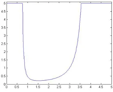
Figure 14: Example of the robot-human potential function; PHuman on the
vertical axis, the distancedHr is on the horizontal axis.
H. The repulsive term prevents the robot from colliding with the human and the attractive term keeps the human within its visibility domain.
Figure 14 shows an example of the robot-human potential function. In this example we have a robotr and a humanH in a two dimensional space, dHr is the distance between them. When ris too close toH thePHuman(dHr) pushes
raway fromH preventing the robot from colliding with the human. Whenris too far thePHuman(dHr) pullsrtowardsH.
Figure 15 shows simulations in NetLogo of the formations of a group of robots and a human being. The formation shape achieved depends on the number of robots, which differs from the work of Gazi and Passino [28], where a predefined shape for a given number of robots is considered.
(a) (b) (c)
Figure 15: Left to right: simulations of the formation of a group of 8 robots and a human being passing a corridor.
Real Robots Implementation
6.3 Olfactory Navigation 6 NON-COMMUNICATIVE SWARMING
laser range finder. The main goal of the implementation was to demonstrate that robots are able to generate a formation and keep the formation while following a leader robot (or a human). The major challenge was to achieve a reliable way to detect the members of the multi robot human team without using any sort of tracking system. In order to mimic relative robot detection and distance estimation robots were provided with a map of the environment in which they localised themselves by using the Adaptive Monte-Carlo localisation method.
As part of the solution we designed an architecture environment for imple-menting: different robot behaviors (aggregation and following), handle com-munication, run distinct robot navigation algorithms (localization and collision avoidance), define different agent types, interact with the hardware involved (actuators and sensors), interface with the users and everything combined with different software platforms (Player, Javaclient and JADE). JADE (Java Agent Development Environment)4was used to take care of the agent’s life-cycle and
other agent-related issues. JADE provides a runtime environment and agent communication and management facilities for rapid and robust agents-based developments. In our demonstration we have developed 4 different types of agents where each one had a clear role in the demo. Note that agents here are different from the classes of agents determined in Section 4.2. Each agent is composed of a set of behaviours that determines how this agent acts or reacts to stimuli. For the demo we have developed several communication, swarm-ing, and following behaviours, and assigned them in different ways to different agent types to get a set of multi-functional agents. By doing so, we are able to share the robots and human poses through the whole team, allowing swarming techniques to take advantage of these essential data.
Figure 16(b) shows the combination of software pieces that are used in our team. Player, from Player/Stage, acts as a Hardware Abstraction Layer, allow-ing us to forget specific hardware problems. JavaClient allows us to connect to the Player server from a Java environment, while JADE provides us the ability to use Agents. In terms of runtime, Agents, and their behaviours, run on top of an agent container provided by JADE, making use of the JavaClient to access Player facilities.
The implementations were demonstrated during the evaluation of theGuardians project’s progress reviews in Brussels in January 2009, and January 2010 in Sheffield (UK) and were met enthusiastically by the audience. In Figure 16(a) video snapshots of the experiments on formation generation and keeping on a group of Erratic’s robots are presented. The one robot provided with a flag, is the leader and simulates the role of the fire fighter; figure 4(a) shows follow-up experiments with a human team member.
6.3
Olfactory Navigation
The Decentralized Asynchronous Particle Swarm Optimization (DAPSO) based high-level path planning is used as the basis for olfactory-based swarm naviga-tion and search in an environment with real chemical (ethanol) gas. The objec-tive is to build and visualize a real-time map of the chemical gas concentrations as well as determine high odour/chemical concentration. In order to improve the self-localization of the robots we have augmented the odometry of the robots
6.3 Olfactory Navigation 6 NON-COMMUNICATIVE SWARMING
(a) (b)
Figure 16: (a) Snapshot of formation generation Erratic robots around the leader in the middle; (b) Software packages applied in our team
with information from gyroscopes of Inertial Measurement Units (IMUs). More-over, we have implemented a priority based robot-to-robot collision avoidance scheme. The navigation of the algorithms from one way-point to a next way point is based on potential functions.
(a) (b)
Figure 17: (a) The experimental facility, Olfactory Arena; (b) Final robot posi-tions in RSSI based triangulation.
The chemical sensor KheNose for the Khepera 3 robots was developed by UC-ISR. To achieve the main tasks substantial hardware and software integration and driver development (such as for example for the IMU devices to be used with the Khepera 3 robots) work was also performed. TCP and UDP communication routines between the robots and the robots and the main computer were also developed.
experi-6.4 Sensor based exploration 6 NON-COMMUNICATIVE SWARMING
mental work on RSSI signal strength based positioning and triangulation by a group of robots. In this experimental study the RSSI signal is viewed as a mea-sure of the distance between robots and the robots try to position/triangulate themselves on an equal ”RSSI distance” to the preceding two robots to form a regular triangular grid. We use a bacterial foraging inspired algorithm as a search strategy for positioning the robots. Moreover, in order to get better signal averaging we used three different strategies for getting the RSSI signal measurements and compare their performance. It is observed that the strategy in which the robots get several measurements on a circle with 25cm radius is fastest and results in a more regular metric grid. The motivation beyond this study is that in applications such as search in a warehouse on fire the commu-nication distance (the RSSI distance in the study) might sometimes be more important than the metric distance between robots. Despite the noise and un-certainty in the signal measurements the robots were able to form an almost regular metric grid.
6.4
Sensor based exploration
The Guardians project aims to have two groups of robots; a group that explores the operative environment (unknown) based on the robots’ sensors and helps the mission’s supervisor to have a better knowledge of the building that is on fire; and another group entering latter that assists the firefighter, as it is explained in the previous sections. Since the first group is sent to the building before the firefighters, when the firefighters start operating, they will have more information about the environment’s risks. The main task of the first group of robots is exploring the environment and generating the map of the building.
Exploration of an unknown environment is a fundamental issue in mobile robotics. Using multiple robot systems may potentially provide several advan-tages over single robot systems namely speed, accuracy, and fault tolerance. Cooperation, map merging, decision making, dealing with uncertainty in lo-calization and reasoning, task sharing and navigation are the most significant research topics in multi-robot exploration. In [42] we have presented an ap-proach for cooperative multi-robot exploration, fire searching and mapping in an unknown environment. The Method minimizes the overall exploration time, making it possible to localize fire sources in an efficient way. In order to achieve this goal, the robots must cooperate in an effective way, so they can individu-ally and simultaneously explore different areas of the environment while they identify fire sources. The proposed approach employs a decentralized frontier based exploration method which evaluates the cost-gain ratio to navigate to target way-points. The target way-points are obtained by an A* search vari-ant algorithm. The potential field method is used to control the robots motion while avoiding obstacles. When a robot detects a fire, it estimates the flame’s position by triangulation. The communication between the robots is done in a decentralized control way where they share the necessary data to generate the map of the environment and to perform cooperative actions in a behavioral decision making way (details in [42]).
6.4 Sensor based exploration 6 NON-COMMUNICATIVE SWARMING
(a) (b)
Figure 18: (a) Three robots exploring a gas free environment (b) Three robots exploring the environment and finding the odor sources.
blue footprint is related to the second robot and the green shows the footprint of the third robot. For an example of the coordination algorithm, when the second robot reached the junction it figured out that the path in the front was already explored and it chose the left path. The full algorithm is functional and it works in different maze structures and with different number of robots.
The same maze structure was tested with the same robots with adding an ethanol odor source in the left side of the environment. The results shows the ef-fect of odor concentration on the behavior of the robots. Figure fig:realvisualISR(b) shows the path that robots took during exploring the environment. The first robot in the first branch made decision to go to the left-way because of a high clue of the odor and wind speed in that direction.
The most important parameter for evaluation of the method is the explo-ration time. The proposed method has been tested with a different number of robots in different mazes. The environment shown in figure 16 was tested by one, two and three Roomba robots separately, once without having any odor or gas source, and once with having an odor source releasing gas in the environ-ment. figure?? shows that the exploration time is a bit more, with having gas cues, however it is not a big difference and they are still comparable. figure ??
shows the time to reach the target (the location of the odor source) in these two scenarios. The chart shows that the robots reach the target much faster with having gas cues rather that without having it, that proves the functionality of the algorithm. Each result is the average of five similar tests. Different tests with constant conditions had similar results with about eight percent variance. The maximum speed of the robots were kept constant in all the tests.
Simulation
The search and exploration algorithm was tested in the real world and also in a simulation world.
6.4 Sensor based exploration 6 NON-COMMUNICATIVE SWARMING
(a) (b)
Figure 19: (a) TExploration time (b) reaching the target (the odor source).
The models of those mazes are also given to the optimal method and then we compared the results of the proposed algorithm with the optimal results. Since the optimal method has the world’s model but the proposed method is exploring the unknown world, it is obvious that the results of the proposed method are always worse than the optimal but this can be a good criteria for evaluating the method.
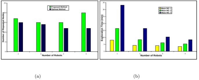
The number of repeated nodes during travel can be another good parameter for measuring the performance of the method. A repeated node is a node that robots pass more than once. Figure 20(a) shows the number of nodes that have been repeated more than once in the optimal method as well as in the proposed algorithm for the maze shown in figure 20. A good conclusion from the graph in figure 20(b) is that there is a trade-off between the number of robots and the size of the world. It shows that the proposed approach is acceptably comparable with the optimal method.
The mazes s have been tested separately with one, two, three and four robots and the results are shown in figure??. The graph shows the average of five tests for each data. The variance was less than one percent. It is obvious that the exploration time improves with higher number of robots. Another conclusion from the graph is that having more robots is more advantageous in a complex maze than in a simple maze. This also proves that the cooperation algorithm in this approach is efficiently functional. Since in the simulation there is no gas cues, the results of this part are very similar to our last presented paper [42].
7 NETWORKING 0 5 10 15 20 25
1 2 3 4
Number of Robots
N u m b e r o f R e p e a te d N o d e s Proposed Method Optimal Method 0 5 10 15 20 25 30 35
1 2 3 4
Number of Robots
E x p lo ra ti o n T im e ( m in )
Maze NO. 1 Maze NO. 2 Maze NO. 3
(a) (b)
Figure 20: (a) Number of repeated nodes, Comparing the results of the proposed method with optimal method (b) Test of various numbers of robots against complexity of the environment, 1: maze of 34, 2: maze of 82, 3: maze of 135 nodes.
The algorithm was tested in the real world with different configuration and different number of robots and the results show the effect of gas cues on the behavior of the robots and it proves that based on the proposed algorithm, robots first explore the area with higher probability of existence of odor sources.
7
Networking
The networking mode is aimed at setting up and maintaining a communication infrastructure. This work faces two major challenges. The first is that the metal or solid concrete present in the warehouse partitions the warehouse into cages which render the reception of the radio problematic. The second challenge is that position detection or localisation is needed. For indoor environments GPS is not available and localisation and mapping (SLAM) has to be based on other sensors. However, because of the smoke the conventional light based sensors may not produce useful data. The radio signal for the wireless communication will not be disturbed by the smoke thus the radio network has to serve as a (coarse) fall back.
7.1
Communication Infrastructure
[image:30.595.136.479.161.300.2]7.1 Communication Infrastructure 7 NETWORKING
topology of the network may change as the circumstances require, for instance to adapt to connection failures [6]. On top of this, the mobility of the robot-nodes further enhances flexibility and enables the swarm to build reception pathways that bridge the transmission gaps. More details on ad-hoc networking in multi-robot scenarios have been presented in [67] and [69].
Hardware platform
The physical communication device has been realized as a gateway module. The gateway manages all required functionality for operating a mobile ad-hoc network including node discovery, maintenance of routing tables, and massage routing. Besides realizing the core functionality of robust message routing the gateway has been developed to support different techniques for energy saving like dynamic frequency and voltage scaling as well as dynamic power down of dormant hardware components including wireless communication processing. Therefore the gateway is equipped with Texas Instrument’s (TI) new OMAP 3 processor. The memory is implemented by a package on package solution on top of the processor. The integration of a commonly used Bluetooth and ultra low-power Wi-Fi single chip offers flexible but efficient use of two communication technologies. An integrated coexistence solution ensures simultaneous operation of Bluetooth and Wi-Fi. Additional wired communication standards like I2C, SPI, UART and high speed USB allows variable expansion of the gateway. This can be used to easily connect additonal components like sensors (e.g. chemical sensors for detection of hazardous agents), actuators, robots or computers to the gateway and enabling optimized heterogeneous communications devices meeting several communication demands. The technical implementation is described in Deliverable D3.5.
Software environment
7.1 Communication Infrastructure 7 NETWORKING
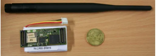
Figure 21: Separate parts (PCB, battery, and antenna) of the Gateway module and their size compared to a coin
and allows a simple identification of clients via the gateway address. The gate-way module automatically publishes this IP of the client to every gategate-way in the whole network and thereby makes it available to the other clients in the network. The default network gateway configuration causes the client to route all network communication to the gateway module. Through this technique the complete routing of the communication is transferred to the gateway and thereby to the mobile ad-hoc communication system. Altogether this enables a standard network communication suite (TCP/IP) based network communi-cation between the gateway and client as well as client and other clients in the network. As an important feature this simplifies the integration of arbitrary nodes into the mobile ad-hoc network and separates as well as hides the network implementation from the application, e.g. all robots, base station, networked position beacon.
Overall System
The whole communication gateway (excluding the antenna) is smaller than a mobile phone whereas the biggest part is the battery pack (figure 21). The big antenna is used to ensure good communication ranges even in hazard en-vironments. The maximal power consumption of the gateway is approximately 2.3W which allows the system to operate for more than 3 hours from a 3.7V battery pack with a capacity of 1950mAh. The runtime can be extended by using a bigger battery. Furthermore the operating system of the system is not optimized regarding power saving at the moment but there is good potential to reduce the average power consumption below 2W. The price for the gateway in low volume production is expected to be around 250 Euro. Compared to mass produced standard router the price is higher but our gateway offers energy ef-ficiency, multi standard communication, a USB interface which allowing easy integration and expansion with additional devices, actors or sensors (tempera-ture and chemical sensors or servo and camera devices). The functionality of the device was shown during different tests and in the final demonstration in a real environments, standard offices as well hazardous parking garage. The gateway has been successfully tested in different environments and network configura-tions. Details have been presented in [31] and are documented in deliverable D.3.5.
7.2 Topology and routing 7 NETWORKING
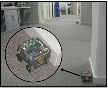
Figure 22: The Bebot robots forming a chain of communication nodes. Long distance communication is realized via multi-hop transmission.
the standards Wi-Fi, Bluetooth and ZigBee. Compared to Bluetooth, ZigBee provides slight power consumption savings, however ZigBee was omitted to ease design complexity. In our case Bluetooth is used to form a local network to avoid large latencies. But as shown in [17] it is possible to form large Bluetooth networks, called scatternets. In addition we have tested a Sub-1-GHz (CC1110 by Texas Instruments) communication technology that provides different wave spreading properties compared to Wi-Fi and Bluetooth communicating in the 2,4 GHz band. Sub-1-GHz technology in our case is considered to be a fall back option if the 2,4 GHz band is jammed: simple status data can be transmitted to reestablish Wi-Fi communication but with lower throughput.
7.2
Topology and routing
7.2 Topology and routing 7 NETWORKING
Figure 23: Considered options for spanning a network: multiple triangles (left) and line topology (right).
link state routing protocol chooses the best reliable routes to guarantee estab-lishing very robust reliable connections within the network. The famous three link state routing protocols are GSR (Global State Routing), OLSR (Optimized Link State Routing) and FSR (Fish-eye State Routing). FSR is better suited for large networks, since it tries to reduce number of updates for far placed nodes than nearer ones. GSR and OLSR were found to be quite suitable for our scenario case, so we have chosen OLSR, which is supported using the OLSRD daemon firmware. More details about the chosen routing protocols can be found in deliverable D3.3.
In the Guardians project several topological distributions of robots were proposed by HNI-UPB and SHU, like forming triangulations or following in a line. We merged the two topologies together to form an adaptive topology, the first trial presented by HNI-UPB in RISE09 workshop followed by SHU in RISE10, The idea of the adaptive triangular distribution is shown in figure 23. In the figure, we can see the fire fighter moving in a narrow corridor at the bottom left of the figure. Here each two nodes try to guide the next node where to be placed to form the triangulation. In case of corridors, the robots switch to forming a line when a triangle cannot be formed, as shown by the discarded node crossed with red colour. After reaching a larger space the dynamic triangulation can once again take place, as shown in the figure while the fire fighter continues roaming to the upper left corner. On the right side of the figure the distribution of nodes is shown but forming a line only, as presented in HNI-UPB demo scenario 2.
7.3 Novelty of the communication system 7 NETWORKING
itself with robot2 becoming a stationary node. Figure 22 shows robot1 and robot2 as stationary nodes forming the communication backbone. Subsequently robot3 became the exploring robot, with the joystick getting control over robot3; thus we have in principle shown how the robots could restore contact with a lost fire fighter. In this example a line of robots has been formed to extend the communication range. For covering a large space in the warehouse and to realize redundant links a mesh consisting of triangles is formed.
7.3
Novelty of the communication system
The main objective of the communication research in theGuardians project, part was the development of a wireless system that is able to provide robust con-nectivity to the robots, the fire fighters and the base station. Robustness in this context means that in case of a failure of a communication node or a single link connectivity is not completely lost. In order to achieve this kind of robustness several options have been considered, like inherent redundancy (a), modula-tion and carrier change (b), node replacement (c), network shrinkage (d), role changing (e), non-communicative swarming (f). Details of the six mentioned methods are discussed in sections 7.2 and 7.1. ’Approaches and algorithms’. Important is that the network maintenance, node discovery, routing, message forwarding via multiple hops, selection of the underlying wireless technology is done automatically as core function of the communication devices. Thus, from the application point of view there is no need to have special knowledge on wire-less networking. To achieve this, it is required to integrate and to encapsulate RF-processing including the physical layer, base band processing, and network-ing on an optimized processnetwork-ing hardware that offers high performance at low power consumption and small size. The developed gateway module is depicted in figure 21.
7.4 Recovery from failures of individual nodes 7 NETWORKING
Figure 24: Example communication network with redundant routes.
Placement of relay nodes to guarantee end-to-end communication or quality of service
Another novelty point was the real implementation and testing of the com-munication protocol, including relay nodes placement. Building up a chain of relay nodes has been used and implemented in many projects before, but most of them used object recognition using cameras, and sometimes with the aid of laser sensors for more accurate distance estimations. In theGuardiansproject we tested various methods and sensors to support the fire fighter / robot fol-lowing feature, which is part of the relay node placement. Here we tested and compared between ultrasonic, Laser, MMW-RADAR and the radio-based Nan-otron sensors for distance estimation, besides testing of various robot recognition methods, via special pattern recognition or via detection of rays, etc. All details on this part are to be found in deliverable D3.5. In the node placement demo, robots perform fire fighter/robot following, and then when distances between them exceed the communication threshold, they change their role and act as relay nodes, to support multi-hop forwarding. This communication threshold can be either measured by the Nanotron system or using the RSSI of Wi-Fi. It is better to use a distance estimator relying on radio quality / quality like these two, and adjust the threshold to at maximum half the quality. This is to ensure that each node can reach at least its second (or maybe higher) neighbour, in case its direct neighbour was damaged or out of order. This is shown in figure 24, where the red links connect between direct neighbours, while the blue links are between second neighbours. Green links are additional links that are supported by other robots from the swarming team in case many of the relay nodes are damaged in one area. More details have been presented in section 7.2.
7.4
Recovery from failures of individual nodes
7.4 Recovery from failures of individual nodes 7 NETWORKING
Figure 25: Network recovery in case of node failures is inherently done by placing nodes in triangular shape. Every node has as minimum two neighbouring nodes. In the case of a node failure links are still available and a route betwe