applications
RODRIGUES, Marcos <http://orcid.org/0000-0002-6083-1303> and
ROBINSON, Alan
Available from Sheffield Hallam University Research Archive (SHURA) at:
http://shura.shu.ac.uk/5194/
This document is the author deposited version. You are advised to consult the
publisher's version if you wish to cite from it.
Published version
RODRIGUES, Marcos and ROBINSON, Alan (2011). Fast 3D recognition for
forensics and counter-terrorism applications. In: AKHGAR, Babak and YATES,
Simeon, (eds.) Intelligence management : knowledge driven frameworks for
combating terrorism and organized crime. Advanced information and knowledge
processing . London, Springer-Verlag, 95-109.
Copyright and re-use policy
See
http://shura.shu.ac.uk/information.html
Terrorism Applications
Marcos A Rodrigues and Alan Robinson, Sheffield Hallam University, Sheffield, UK
Abstract
The development of advanced techniques for fast 3D reconstruction and recognition of human faces in unconstrained scenarios can significantly help the fight against crime and terrorism. We describe a 3D solution de-veloped within Sheffield Hallam University that satisfies a number of im-portant requirements such as operating close to real-time, high accuracy in recognition rates, and robust to local illumination. Experimental results in 3D face recognition are reported and two scenarios are provided that can be used to exploit the outcomes of this research for forensic analysis and for flagging potential threats in counter-terrorism.
Introduction
looking into technological needs for increased recognition rates. It lends it-self to the integration of existing 2D databases and standard CCTV data with unique generation and manipulation of 3D footage. It has the poten-tial to greatly improve the effectiveness of CCTV gathering, as it will make it possible to recover 3D information from video sequences in a novel and effective way.
We have been developing and patenting unique methods of acquiring 3D models using uncoded or lightly-coded structured light scanning – each model being recorded within one single video frame (40ms). The struc-tured light principle is well known: project a pattern of light onto the target surface, and record the deformed pattern in a camera with a known spatial relationship to the projector. We have developed structured light systems-for modelling faces and many other surfaces in industrial and medical ap-plications [1—7].
The advantages of structured light scanning over stereo vision methods are numerous for instance: 1) the computationally intensive Correspondence Problem is avoided as only one image is used and the problem is then shifted towards the less computational intensive stripe indexing problem, 2) there is an explicit connected graph that makes surface reconstruction straightforward, 3) the density of the data can be controlled in the pattern design, and 4) smoothly undulating, featureless surfaces can be easily measured and this is not the case with stereo vision. The key disadvantage of structured light methods is that as the distance between projector, target and camera become greater, the light intensity reaching the camera be-comes weaker. This means that it may be difficult to discriminate a dense light pattern, especially if a colour-coding scheme is used.
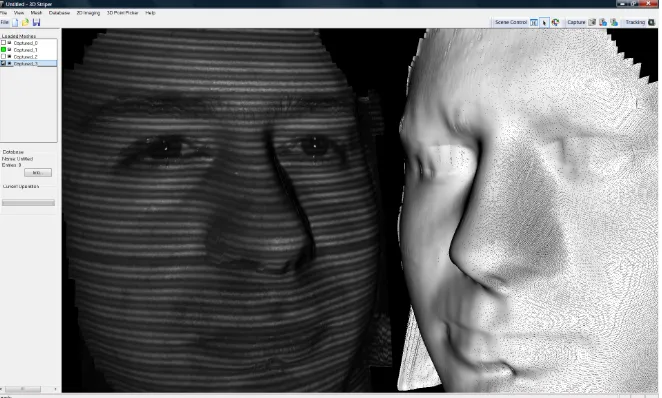
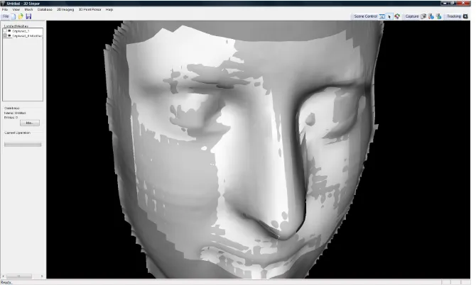
data is that the visible spectrum camera contains normal texture of objects in the world, while the NIR camera images are illuminated by a NIR pat-tern of stripes as shown in Fig. 1.
Fig. 1 Left, an example 3D model with NIR stripes on, right, wire mesh 3D model.
The way the 3D CCTV concept operates on human faces is highlighted as follows. A set of face detection and eye tracking routines have been im-plemented [7] which operate on the visible spectrum camera. As soon as a face is detected that satisfies predefined conditions (width and height larger than a minimum number of pixels) the projector stripes are switched on and an NIR image is taken. Both images are saved to disk, the NIR con-tains stripe information that allows 3D reconstruction in real time (i.e. within a video frame of 40ms) and the visible spectrum image contains texture information that can be overlaid onto the 3D model.
Steps in 3D Face Reconstruction and Recognition
Grand Challenge FRGC [8] has allowed the wider research community to test recognition algorithms from standard 2D and 3D databases, a severe limitation is that it was not designed to cater for real-time requirements. The FRGC database is standardized such that an application can load pre-formatted data for feature extraction and recognition. 3D data were recon-structed from human subjects taken from a frontal, but arbitrary view point and, given that these are large files containing the structure of the vertices in 3D, this rules out the possibility of testing algorithms in a real-time scenario. Therefore, while 3D data were profitably used to test recognition algorithms in the FRGC, the process does not represent a natural way in which 3D facial recognition systems are to be deployed. The 3D CCTV concept described here provides a contribution towards solving real-time issues in 3D face recognition.
There are prescribed steps that need to be performed in order to achieve fully automatic 3D face recognition based on vision systems:
• 2D tracking and filtering: face and eye tracking; image filtering; im-age correspondence (stereo) or projection pattern detection (structured light methods)
• 3D reconstruction and post-processing: generation of 3D point cloud and mesh triangulation; noise removal; 3D hole filling; mesh smooth-ing (optional); mesh subdivision (optional); pose normalization; fea-ture extraction
• Enrolment and recognition: features are enrolled in a database for sub-sequent identification (one-to-many) or verification (one-to-one) rec-ognition using appropriate algorithms
These steps are described in the following sections.
2D Tracking and Filtering
in-stance, on any image there could be various detected faces and some might not be real faces. The same problem happens with eye detection; the rou-tines normally detect more eyes than there are in the scene. In order to solve this problem a number of constraints are defined: first, there should be only one face detected in the image and the face width must be larger than a certain threshold (300 pixels in our case); second, there should be only one left and only one right eye detected in the image, and these must be within the region of interest set by the face detection; third, the position of the face and eyes must not have moved more than a set threshold since last detection (10 pixels in our case) so to avoid inconsistent shots caused by rapid motion.
Fig. 2 Left, eye tracking in 2D using the visible spectrum camera. Right, a striped NIR image is taken and converted into 3D.
Fig 2 shows the visible spectrum camera continuously tracking and detect-ing (possibly multiple) faces and eyes, but only when the above conditions are satisfied a shot is taken. In this way, the system is apparently idle until someone places their face in front of the camera. When face and eyes are positively identified a near-infrared line pattern is projected onto the sub-ject and a shot is taken and reconstructed in 3D as shown in the right of Fig. 2.
mean filter. This enables the detection of the stripe patterns in the image. Given that we know the geometry of the camera and projector, by knowing the stripe indices we can now fully reconstruct in 3D by trigonometry. While 3D models are shown in Figures 1 and 2, details of the process have been published in [10].
3D Reconstruction and Post‐Processing
3D reconstruction is achieved by mapping the image space to system space (camera + projector) in a Cartesian coordinate system. We have developed a number of successful algorithms to deal with the mapping as described in [2, 10]. Once this mapping is achieved, a 3D point cloud is calculated and the output is triangulated using the connectivity of the vertices.
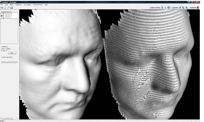
Once the surface shape has been modeled as a polygonal mesh, a number of 3D post-processing operations are required: hole filling, mesh subdivi-sion, smoothing, and noise removal. There are several techniques that can be used to fill in gaps in the mesh such as the ones discussed in [11, 12, 13]. From the techniques we considered, we tend to focus on three meth-ods namely bilinear interpolation, Laplace, and polynomial interpolation. We found that the most efficient method for real-time operation is bilinear interpolation [14].
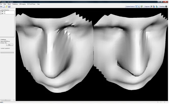
Fig. 3 Post‐processing showing a sub‐divided mesh (left) and non‐subdivided (right)
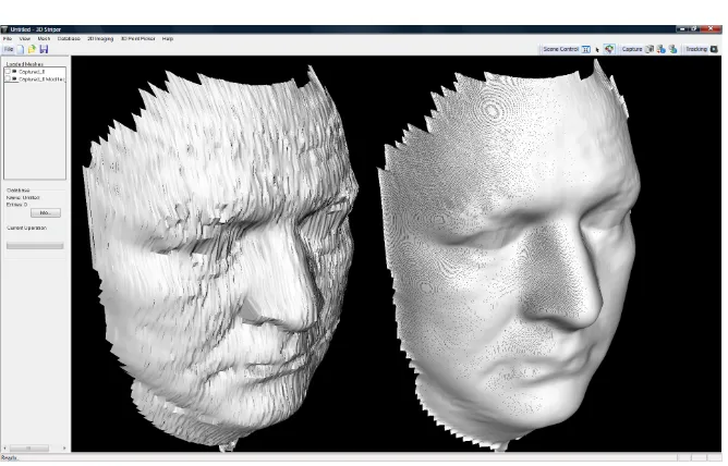
Fig. 4 The effects of smoothing.
Noise removal is mainly concerned with the region around the eyes, as considerable amount of noise exist due to eyelashes and unwanted reflec-tions as it can be seen from the raw unsmoothed model on the left on Fig 4. A natural solution would be to replace the vertices in the eye by a spherical surface centred somewhere behind the face model. By experimentation, we chose the centre of the sphere at a position 40mm behind the face model in the same Z-axis as the centre of each eye. An elliptical mask is marked centred on each eye, and all vertices within the elliptical surface have their values replaced by their spherical counterparts. This however, resulted in unnatural looking models. A second solution, which is conceptually sim-pler, is to punch an elliptical hole centred at each eye and then fill in the holes with bilinear interpolation. This has proved to work well for the face models and it is the solution that is adopted here.
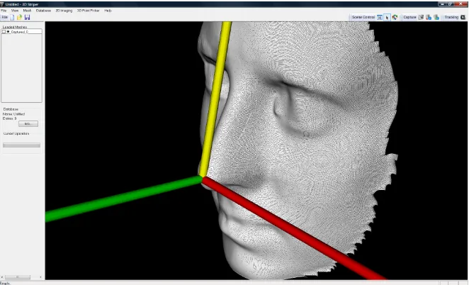
Pose Normalization and Sampling
with the horizontal position of the eyes, the Y-axis forms a constant angle of π/10 with a point located on the front between the two eyes, and the Z-axis points away from the model such that all depths are negative.
Fig. 5. The standard pose with the origin at the tip of the nose
The algorithm to achieve this standard pose is described as follows [1] (given that we know the position of the eyes (E1and E2) in 3D:
1. Estimate the angle ß1 in the XY-plane between E1and E2
2. Centered on E1 rotate the mesh around the Z-axis by angle ß1: Rot(
z, ß1 )
3. Estimate the angle ß2 in the YZ-plane between E1and E2
4. Centered on E1 rotate the mesh around the Y-axis by angle ß2: Rot(
y, ß2 )
5. Find the intersection point on the mesh (above the eyes, on the front) of the arcs centered on E1 and E2 with radius 0.75 of the inter-ocular distance. Mark this point as F
6. Find the tip of the nose. This is defined as the highest point on the mesh below eye positions within a search threshold of one inter-ocular distance. Mark this point as T
8. Centered on T, rotate the mesh around the X-axis by (π /10 — ß3): Rot( x, π /10 — ß3 )
9. After this rotation, the highest point on the mesh defining T might have slightly changed. Repeat steps 6, 7 and 8 until (π /10 — ß3) is below a set threshold.
[image:11.595.133.468.327.528.2]900 points are sampled for recognition defined within the boundaries of four planes: two horizontal planes (top and bottom) and two vertical planes (left and right) set the limits for sampling the 3D structure. All calculations are performed in 3D and the sampled points form the feature vector that uniquely characterizes a face and it is used for recognition. Figure 6 shows a face structure together with the sampled points.
Fig. 6. Sampled data points from the face are marked lighter.
The delimiting planes for sampling (top, bottom, left, right) are defined as:
• ∏Top: parallel to XZ-plane at point (0, 1.3(E2 — E1), 0 ) • ∏Bottom: parallel to XZ-plane at point ( 0, -0.66(E2 — E1), 0 ) • ∏Left: parallel to YZ-plane at point (-(E2 — E1), 0, 0 )
Enrolment and Recognition
[image:12.595.129.463.316.546.2]3D recognition algorithms based on eigenvector decomposition [15] were tested on a 3D database where 300 models were used as follows. First 100 subjects were enrolled in the database. Then a second (unseen) model of each person was used for testing identification and set the threshold for verification allowing the lowest possible FAR (false acceptance rate). Fig-ure 7 shows an example of output recognition: the image on the left is the unknown face and the image on the right is the closest in the database found by the algorithm. A distance measure of 32 is indicated, and these measures are used to estimate the correct threshold for minimum FAR.
Fig. 7. Example of recognition showing the closest match and a distance measure
Figure 8 is the 3D counterpart to Figure 7: here the 3D models generated and used by the recognition algorithm are shown. The model on the right was used for enrolment and the model on the left is the unknown model.
it was noted that no distance was greater than 50. In order to set the correct threshold for minimum FAR, we then tested the database with models that were not enrolled in the database. It is expected that the closest match to these models (there is always a closest match) would have a distance larger than 50. In fact, this was verified and the system has proved to work with no FAR if the threshold was set to 50.
Fig. 8. The 3D models generated and used by the algorithm corresponding to the images shown in Figure 7.
We tested the algorithms in a simulated environment to verify its real-time performance from eye tracking to 3D reconstruction and recognition and logging the results with time stamps onto an HTML file. We used a Sony Vaio computer, Intel Core 2 Duo, 2.4GHz, 4GB memory. It has been shown that the methods presented here lend themselves to real-time opera-tion as, from the moment the eye tracking algorithms lock on the eyes, it takes 1second 200millisencods to perform the following operations:
• Take a shot in 2D
• Run image filters (median and weighted mean filters) • Detect the stripes in the image
• Perform hole filling on the mesh • Determine the location of eyes in 3D
• Punch a hole in the eyes, fill with bilinear interpolation • Find tip of the nose
• Normalize pose with origin at the tip of the nose • Determine the sampling planes and sample the mesh • Replace noisy points by reflection
• Search the database for the closest match • Display results of recognition on screen
• Save to log file: time stamp, current image, closest match • Continue eye tracking and repeat the sequence
Application Scenarios to Forensics and Counter‐Terrorism
Having demonstrated the efficacy of the approach in terms of robust re-construction and recognition and its real-time credentials, we turn our at-tention to possible applications to forensics and counter-terrorism – in ad-dition to the most obvious application of identity verification for access control.
3D-2D Identification from Standard 2D Facial Databases
3D-2D Identification from Standard 2D CCTV Video Sequences
The purpose is to compare standard 2D CCTV with 3D models acquired either from 3D CCTV as discussed above or 3D acquisitions from a person in custody. The method proposed here can enable substantial improve-ments in detection rate of CCTV footage. The Metropolitan Police in Lon-don states that the identification rate from CCTV is about 20% (personal communication). The 3D CCTV concept has the potential to substantially increase identification rates through the integration of 2D and 3D data. This can be achieved by projecting 2D video footage onto a plane in a 3D environment and by providing the means to manipulate 3D models over the projective plane. In this way for instance, 2D profiles can be compared to 3D model profiles.
15
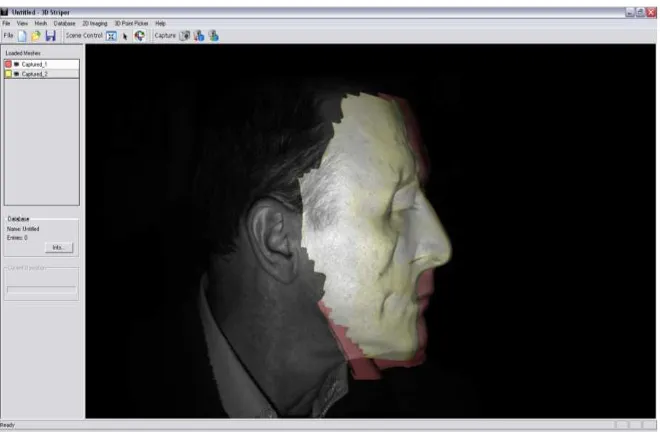
[image:16.595.132.461.145.378.2]Fig. 9. Standard CCTV footage is projected on a 3D screen allowing the comparison of profiles
Fig. 10. The 3D model fits the 2D profile obtained from standard CCTTV
FP7-SEC-2009.2.2.2 Integrated Comprehensive Approach to Airport Security 4D-SAS
13
since 2002. The principal idea behind the proposed 3D-3D face recognition method is to describe facial
data using a deformable facial model. The deformable model captures the details of an individual's face
and represents this 3D geometry information in an efficient 2D structure, called geometry image. This
structure is subsequently analyzed in the wavelet domain and the spectral coefficients define the final
metadata that are used for comparison among different subjects. The physical (geometrical) modelling of
the human face allows greater flexibility, better understanding of the face recognition issues, and
requires minimum training compared to a statistical modelling approach. [8,9,10,11].
Their algorithms participated in the National Institute of Standards & Technology (NIST) Face
Recognition Grand Challenge and achieved the top place in the 3D (shape only) track of NIST’s Face
Recognition Vendor Test 2006. The average Verification Rate is above 97% for 0.1% False Accept Rate.
This means that in an access control scenario, authorized persons will be rightfully granted access with a
97% probability, while unauthorized persons will be falsely granted access with only 0.1% probability.
Some open research issues to be addressed include:
1.
Real-time performance. The proposed 3D system is significantly faster than most 3D systems as
the comparison of the biometric signatures is extremely efficient. However, it currently takes several
seconds to create such a biometric signature of a person. We intend to use parallel threads, on
multi-core PC’s and/or CUDA implementations on GPU’s in order to get the total time under 3s for
medium-sized databases (under 10,000 people).
2.
Missing data/off-poses. A common problem in real operating conditions (off-centre poses) is that a
subject’s face is partially captured; usually there are missing data from one side of the face w.r.t. a
vertical facial axis rotation. Typically, part of the left or the right side is missing and this partly cancels
the pose-invariant advantage of 3D face recognition. SHU have developed algorithms to recover
facial symmetry and this and other methods will be pursued by the project.
3D-2D Identification from Standard 2D Facial Databases
The idea in 3D-2D recognition is that accuracy can be improved over 2D-2D recognition by using a 3D
subject against a standard 2D database. The comparison can take place either in 3D space, where the
2D data are reconstructed in 3D, or in 2D space, where 3D data are projected in 2D. This
cross-dimensionality comparison is a classic computer vision problem, but advantage can be taken of the
restricted nature of the application (human faces only). The 3D CCTV concept as proposed here allows
3D facial models to be reconstructed from saved footage: their position and orientation of the 3D facial
models can then be automatically manipulated to match existing 2D photographs of suspects in a
database at a higher accuracy than a 2D-2D comparison for challenging datasets in terms of pose and
lighting. Incomplete facial models (say, a face seen from only one side) can be pose-normalized and,
through mesh reflection, the unseen side of the face can be reconstructed together with the reflected
texture.
3D-2D Identification from Standard 2D CCTV Video Sequences
The novel concept is to compare standard 2D CCTV with 3D models acquired either from 3D CCTV as
described above or 3D acquisitions from a person in custody. The method proposed here can enable
substantial improvements in the detection rate of CCTV footage. The Metropolitan Police in London
states that the identification rate from CCTV is about 20% (personal communication). The 3D CCTV
Theme 10: Security Collaborative projects: Integration project
FP7-SEC-2009.2.2.2 Integrated Comprehensive Approach to Airport Security 4D-SAS
13
since 2002. The principal idea behind the proposed 3D-3D face recognition method is to describe facial
data using a deformable facial model. The deformable model captures the details of an individual's face
and represents this 3D geometry information in an efficient 2D structure, called geometry image. This
structure is subsequently analyzed in the wavelet domain and the spectral coefficients define the final
metadata that are used for comparison among different subjects. The physical (geometrical) modelling of
the human face allows greater flexibility, better understanding of the face recognition issues, and
requires minimum training compared to a statistical modelling approach. [8,9,10,11].
Their algorithms participated in the National Institute of Standards & Technology (NIST) Face
Recognition Grand Challenge and achieved the top place in the 3D (shape only) track of NIST’s Face
Recognition Vendor Test 2006. The average Verification Rate is above 97% for 0.1% False Accept Rate.
This means that in an access control scenario, authorized persons will be rightfully granted access with a
97% probability, while unauthorized persons will be falsely granted access with only 0.1% probability.
Some open research issues to be addressed include:
1.
Real-time performance
. The proposed 3D system is significantly faster than most 3D systems as
the comparison of the biometric signatures is extremely efficient. However, it currently takes several
seconds to create such a biometric signature of a person. We intend to use parallel threads, on
multi-core PC’s and/or CUDA implementations on GPU’s in order to get the total time under 3s for
medium-sized databases (under 10,000 people).
2.
Missing data/off-poses
. A common problem in real operating conditions (off-centre poses) is that a
subject’s face is partially captured; usually there are missing data from one side of the face w.r.t. a
vertical facial axis rotation. Typically, part of the left or the right side is missing and this partly cancels
the pose-invariant advantage of 3D face recognition. SHU have developed algorithms to recover
facial symmetry and this and other methods will be pursued by the project.
3D-2D Identification from Standard 2D Facial Databases
The idea in 3D-2D recognition is that accuracy can be improved over 2D-2D recognition by using a 3D
subject against a standard 2D database. The comparison can take place either in 3D space, where the
2D data are reconstructed in 3D, or in 2D space, where 3D data are projected in 2D. This
cross-dimensionality comparison is a classic computer vision problem, but advantage can be taken of the
restricted nature of the application (human faces only). The 3D CCTV concept as proposed here allows
3D facial models to be reconstructed from saved footage: their position and orientation of the 3D facial
models can then be automatically manipulated to match existing 2D photographs of suspects in a
database at a higher accuracy than a 2D-2D comparison for challenging datasets in terms of pose and
lighting. Incomplete facial models (say, a face seen from only one side) can be pose-normalized and,
through mesh reflection, the unseen side of the face can be reconstructed together with the reflected
texture.
3D-2D Identification from Standard 2D CCTV Video Sequences
The novel concept is to compare standard 2D CCTV with 3D models acquired either from 3D CCTV as
16
Fig. 11. No amount of transformation can fit a wrong 3D model (lighter) onto the 2D pro‐ file
3D-3D Identification flagging in continuous mode in counter-terrorism applications
The main idea behind this application is to flag previously seen faces by continuously generating new models, enrolling into the database, and per-forming identification. A mobile robot platform can be used or a stationary 3D camera positioned at a strategic location in public places such as shop-ping malls and airports. The system is set into a fully automatic mode tracking faces and eyes, performing identification and enrollment. When a face is found in the database within a given threshold, the system will im-mediately flag this. It can be used to check the movements of suspected agents in a theatre of war or within a civilian environment in a shopping mall.
14
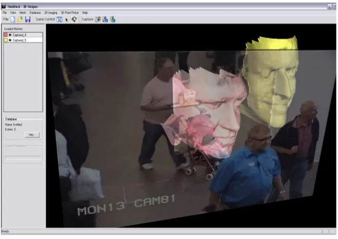
concept has the potential to substantially increase identification rates through the integration of 2D video and 3D data. This can be achieved by projecting 2D video footage on a plane in a 3D environment and by providing the means to manipulate 3D models over the projective plane. In this way for instance, 2D profiles can be compared to 3D model profiles. The simulated pictures below illustrate the concept.
A standard 2D CCTV video footage is projected onto a plane in a 3D modelling environment. 3D facial models of suspects are overlaid on the same screen. Through a combination of rotation, translation, and zooming, a 3D profile can be fitted onto the 2D footage.
In this example of the above figure, the pink (darker) model fits the person’s profile. Using the “wrong” 3D model, coloured yellow (lighter), no amount of transformation can fit the profile. Such methods and appropriate tools will be designed to use off-line and can be used both for positive identification and for elimination purposes.
Some open research issues to be addressed in the case of 3D-2D facial recognition include:
1. Investigate relighting as opposed to unlighting. Current approaches attempt to unlight a 2D facial
image (thus deriving the albedo), aided by 3D facial models, in order to minimize the lighting factor in 2D image comparison. Such unlighting techniques have had limited success because there is generally no ground truth in the albedo estimation process. We have early indications that relighting (i.e., changing the lighting conditions of a 2D facial image to match that of another with the aid of a 3D model) can be successful.
2. Develop better landmark trackers. A key issue in 3D-2D recognition is the ability to detect facial
landmarks, which will guide the mapping from 2D to 3D or vice-versa. Landmark detection algorithms have shown notorious aversion to robustness. However, we have early indications that a technique using constraints based on a facial model may bridge the robustness gap.
3. Profile-based recognition. The profile of a human face is quite distinctive and is available in side
views. Therefore it is possible to try to match the 3D model of a subject against a 2D profile, by optimizing the affine transformation of the 3D model with the target of matching its 2D projection against the given 2D profile.
1.2.3 Real Time Detection Technologies for Explosives, Toxic Agents, Illicit Drugs
Conclusion
We have presented methods for real-time 3D face recognition from face and eye tracking in 2D to fast 3D reconstruction, feature extraction, identi-fication and veriidenti-fication. Based on geometry alone, the reported recogni-tion accuracy is a perfect 100% with zero FAR. We have used 300 distinct models in our experiments. Equally significant, we have shown that the process from 2D tracking to 3D recognition takes only 1second
200milliseconds per subject and thus, can be used in a real-time scenario given the speed and accuracy of the 3D recognition.
While the methods presented here have direct application in face recogni-tion tasks for access control, we have discussed the possible applicarecogni-tion into a number of interesting domains such as integrating the proposed 3D CCTV concept with standard 2D CCTV in person identification scenarios such as forensic investigations. We also discussed the issue of operating in continuous identification and flagging mode for applications in counter-terrorism and intelligence.
Future work among others includes the design and implementation of mesh compression methods and algorithms enabling fast network-based 3D recognition systems.
References
[1] M.A. Rodrigues, A. Robinson, Real-Time 3D Face Recognition using Line Projection and Mesh Sampling. Eurographics Workshop on 3D Ob-ject Retrieval (2011) H. Laga, T. Schreck, A. Ferreira, A. Godil, and I. Pratikakis (Editors), pp 1—8.
[3] M.A. Rodrigues, A. Robinson, W. Brink, Fast 3D Reconstruction and Recognition, 8th WSEAS Int Conf on Signal Processing, Computational Geometry & Artificial Vision, Rhodes, 2008, p15-21.
[4] M.A. Rodrigues, A. Robinson, W. Brink, "Issues in Fast 3D Recon-struction from Video Sequences", Lecture Notes in Signal Science, Inter-net and Education, Proceedings of 7th WSEAS International Conference on MULTIMEDIA, INTERNET & VIDEO TECHNOLOGIES (MIV '07), Beijing, China, September 15-17, 2007, pp 213-218.
[5] M. Rodrigues, A. Robinson, L. Alboul, W. Brink,"3D Modelling and Recognition", WSEAS Transactions on Information Science and Applica-tions, Issue 11, Vol 3, 2006, pp 2118-2122.
[6] A. Robinson, L. Alboul and M.A. Rodrigues,"Methods for Indexing Stripes in Uncoded Structured Light Scanning Systems", Journal of WSCG, 12(3), 2004, pp 371-378
[7] M.A. Rodrigues and Alan Robinson, Image Processing Method and Apparatus, European Patent Office, Patent GB2426618, 29 Nov 2006. Also published as WO2005076196 (A1), GB2410876 (A).
[8] FRGC, (2005). The Face Recognition Grand Challenge, http://www.frvt.org/FRGC/
[9] Bradski, G.R and V. Pisarevsky (2000). Intelapos’ Computer Vision Library: applications in calibration, stereo segmentation, tracking, gesture, face and object recognition. Computer Vision and Pattern Recognition. Proceedings. IEEE Conference on Volume 2, 796 – 797.
[10] Robinson, A., L. Alboul, and M. Rodrigues (2004). Methods for in-dexing stripes in uncoded structured light scanning systems. Journal of WSCG, 12(3) 371–378, February 2004.
[12] Wang, J. and M. M. Oliveira (2003). A hole filling strategy for recon-struction of smooth surfaces in range images. XVI Brazilian Symposium on Computer Graphics and Image Processing, pages 11–18, October 2003.
[13] Wang, J. and M. M. Oliveira (2007). Filling holes on locally smooth surfaces reconstructed from point clouds. Image and Vision Computing, 25(1):103–113, January 2007.
[14] Rodrigues, M.A, and A.Robinson (2009). Novel Methods for Real-Time 3D Facial Recognition. ATINER 5th Int Conf on Computer Sc and Info Sys, Athens, Greece, 27-30 July 2009.