Upper Limb Motion Intent Recognition Using Tactile Sensing
In Stroke Patients
Thekla Stefanou
1Dr Ailie Turton
2Dr Alexander Lenz
3and Dr Sanja Dogramadzi
4Abstract— Focusing on upper limb rehabilitation of weak stroke patients, this pilot study explores how motion intent can be detected using force sensitive resistors (FSR). This is part of a bigger project which will see the actuation and control of an intent-driven exoskeleton. The limited time stroke survivors have with their therapists means that they do not get enough training. Aiming to replicate therapist prac-tices of recognising a patient’s intention to move, a pilot study of a tactile detection system is presented. The goal is a system that will perform consistently even with patients who cannot initiate any movement, due to low muscle strength and control ability. Cur-rently available devices do not offer the robustness and performance necessary; whereas Electromyogra-phy (EMG) sensors, a well-established method, is af-fected by factors like skin moisture, BCI (Brain Com-puter Interface) has a slow response time. A different approach is taken in this study which uses tactile sensing to recognise motion intent. The experiments are performed with a healthy subject emulating low muscle activation conditions. An overall accuracy of 80.45% is achieved when detecting forearm and upper arm muscle contractions and hence motion intent.
I. INTRODUCTION
A. Background
Rehabilitation aids stroke survivors learn new ways of movement with the potential to help them regain use of their affected limb. Recovery is influenced by quantity of training and the specific tasks practised[23]. Physician’s guidelines suggest a combination of repetitive task training (RTT), including constraint-induced movement (CIMT), depending on the individual’s ability[31]. During active-assisted exercises the therapists wait for the initiation of the movement by the patient; these cues are either visual or haptic. They then support and guide the limb through the completion of the exercise. The visual feedback, of the movement of the limb that occurs following muscle contraction, and proprioception of the patient improves the rebuilding of neural pathways[1].. Discussions with the therapists in the field indicated that where there is a lack of mobility they usually feel the soft tissue in the proximity of the actuation muscle to detect the onset of motion. As the muscle contracts it shortens, resulting in a shape change that can be
*This work was not supported by any organization
1Thekla Stefanou is with the FARSCOPE, BRL, University of
Bristol, UWE, Bristol, UK
2Dr Ailie Turton, University of the West of England, UK 3Dr Alexander Lenz and3Dr Sanja Dogramadzi with the Bristol
Robotics Laboratory, University of the West of England, UK
felt when one lightly rests their hand on it. Therefore, the force felt by the therapist is used as the onset of intention of motion.
B. Rehabilitation Devices
Given the actual ratio of occupational therapists to patients in the NHS, compared to the ideal[21], the therapy time for each patient is lower than that required. That is where rehabilitation devices come in. Robotic devices have great potential in assisting therapists with rehabilitation[20] and that is why the medical sector does not shy away from their use[31]. The aim of the system proposed is to mimic the recognition of movement intention in this human-human interaction. Recognising intention, using the same cues as therapists do, the arm can then be guided through a motion without the need of a therapist.
Within the last two decades, multiple upper-limb re-habilitative devices/exoskeletons have been developed. They can support all degrees of freedom of the shoulder, elbow, forearm and wrist through the full range of mo-tion[26][2]. Commercially available devices are being used in conjunction with traditional therapy[34]. Intention-driven ones[29] are very but also lack robustness[9].
A variety of sensors have been used in detecting move-ment intent; these include sEMG, torque and EEG (Elec-troencephalography) sensors, recording brain activity for BCI (Brain Computer Interface) systems. EMG signals, which have been the subject of studies for decades, sense motor-neuron train spikes. They are being used exten-sively in assisted living, rehabilitation and prosthetic systems; nonetheless, EMG controlled systems have still not reached acceptable consistency of performance re-quired[9]. There are limitation on the conditions under which they are being used[7]. For example, it has been shown that adipose tissue (fat) can affect amplitude and create crosstalk between signal recordings[18] while skin moisture also affects signal acquisition[30]. Hence, they are usually not the only intent detection sensors used in a user driven system.
on the user’s ability to produce detectable torques.
Steering away from EMG triggered con-trollers,developments by Barsotti et al[3] included a Motor Imagery (MI) based BCI to control the BRAVO (Brain computer interfaces for Robotic enhanced Action in Visuo-motOr tasks) exoskeleton[4]. Tests with stroke patients demonstrated an classification accuracy of 82.5% during reaching-grasping exercises. The limitations in this approach are seen in the response time of the system; it takes about (3.45 ±1.60)s to initiate a movement. This would cause issues if the patient needs to urgently terminate the movement as even greater delays would occur taking into account the actuation stopping time.
In prosthetics, force Myography (FMG), also referred to as tactile imaging, has shown promising results when used in intent recognition. The idea that the volumetric and shape changes that take place within the muscle can be monitored and used as an indication of motion intent was first captured by Moromugi et al[22]. Push buttons, indented in the skin, with load sensors were used to capture "muscle stiffness" for the purpose of actuating a prosthetic hand. Wininger,Nam-Hun Kim et al performed one of the first studies implementing tactile sensing to predict grip force in hand prostheses[35]. Creating a grip dynamometer, Wininger mapped the readings measured during gripping and the pressure exerted by the forearm on the FMG cuff. Testing the concept on healthy young adults, they concluded that FMG is a useful alternative to EMG. Furthermore, a high resolution tactile sensor system developed by Schürmann was used in a proof of concept study carried out by Castellini et al to create tactile images of the anterior forearm[5], followed by feasibility study that indicated tactile sensing offers more stability than sEMG[28]. Later, the same sensory technology was embedded and tested in a tactile sensor bracelet[17]. Lastly, a feasibility study performed by Cho with amputated subjects indicated that FMG resulted in classification accuracies of over 70% in all grip classifications attempted[6].
In this paper we investigate how tactile sensing can be used to detect motion intent in stroke patients with upper limb paralysis in order to actuate an exoskeleton that will help them perform rehabilitative exercises. The challenges are different to prosthetics as the user’s strength that needs to be detected could be as low as 5%[8] of their nominal strength. To start with, we describe the set up used for this tactile motion intent recognition system and the proof-of-concept experimen-tal observations are summarised. Following that, the motion intent recognition system is tested using hand and elbow motions.
II. METHODOLOGY
The FMG approach is adopted, aiming to find a robust solution that offers a fast, consistent and accurate motion intent detection system for stroke patients. The rehabilitative system developed aims to sense this intention of movement and help the patient through certain rehabilitation exercises. The aim of the system is to mimic the way therapists use their sense of touch to detect the intention of motion. The experiments that follow try to emulate the low activation which would be the result of a weak muscle response, as would be the case with some stroke patient, and determine the feasibility of such an approach. Three different experimentation stages were completed; starting off with a proof-of-concept experiment followed by testing of the motion intent detection system on gripping and elbow motions. Indications as to whether a particular movement is being attempted will be acquired by monitoring the activity in the identified muscle areas. Muscle contraction or relaxation will alter the shape of the proximal tissue area, causing contact force changes between the arm (forearm or upper arm) and the support. It is expected that these changes will be detectable regardless of muscle depth level.
[image:2.595.319.555.525.642.2]Gripping was the first movement the concept was tested against. The muscles providing the main forces during gripping are the three extrinsic ones[19] located in the forearm; flexor digitorum superficialis (FDS), flexor digitorum profundus (FDP) and flexor pollicis longus (FPL), Fig. 1.
Fig. 1: The flexor digitorum profundus (FDP), flexor digitorum superficialis (FDS) and flexor pollicis longus muscles (FPL) - in all three diagrams the posterior compartment of the forearm is shown[36].
A. Stage1
For the first stage of experiments we determined that the sensor system sensitivity is good enough to detect contact force changes in the forearm during low grip strength motions; as would be expected in a weak stroke patient. To perform these experiments a measurement device was required to measure the grip forces exerted.
1) Grip Holder: An analog grip strength meter, a
[image:3.595.348.521.175.271.2]Saehan hydraulic hand dynamometer[27], was utilised to monitor the grip strength used by the subject. Such devices are mainly used to evaluate grip strength after hand surgery or during a rehabilitation program. Also, the minimum strength requirement the sensors needed to detect was evaluated.
Fig. 2: Sehan hydraulic hand dynamometer used to measure grip strength[27].
Stroke survivors are at their weakest right after the stroke incident That is when their affected limb has on average 18% of the unaffected side’s nominal grip strength[32]; this can be as low as 5-10%. According to a study performed in Britain[8], the peak optimum median grip is 51kg and 31kg for male and female respectively. Thus, 5-10% of the latter calculates to 1.55-3.10kg (15.21-30.41N). Seeing as the resolution of the device is only 2kg (19.62N), the indicator was kept just below that. Therefore, the goal was to detect the contact force changes that take place between the forearm and its ‘enclosure’, during gripping motions with what is determined to be as <6.45% of the average nominal strength of females.
2) Sensing: The next step was to choose the
sen-sors. Piezoresistive tactile sensors were preferred over capacitive sensor as the latter are very susceptible to noise[33]. The Interlink Electronics flexible FSRs were chosen as they provide the largest active surface area for the cheapest price[11].
The FSRs have a conductor substrate with a printed interdigitated circuit pattern and another one coated with carbon-based ink; when a force is applied, the conductive substrate deforms and contact is made with the printed circuit line varying the resistance across it and, as a result, proportionally the voltage. They require a simple interface and their size (thickness of 0.46mm) allows for easy integration.
These sensors have a minimum force detection of 1N and a maximum repeatability error of±2%. The sensor
sensitivity exhibited an exponential behaviour, Fig. 3. Experiments were ran to determine its sensitivity by recording the readings as 100g weights were added on the sensor, making contact only with its ’active’ area.
0 100 200 300 400 500 600 700 800 900 1000
Force (N)
0 0.5 1 1.5 2 2.5 3
Voltage (V)
[image:3.595.114.240.284.376.2]FSR Sensitivity
Fig. 3: Sensor sensitivity, force-to-voltage conversion de-termined by experimentation.
Placement of the sensors on the support, with respect to the monitored muscles, was done as discussed earlier; centrally where it makes contact with the posterior and anterior forearm. Two sensors were used, sensor1 was placed at the top, anterior part of the forearm (palm facing upwards), and sensor2 at the bottom of the inner lining of the support, posterior forearm.
3) Forearm Support: Finally a forearm brace was
built. To ensure good contact of the forearm with the sensors a tight fit was essential hence there was a need for adjustability. Avoiding obstruction of movement and minimising the weight and cost were also important factors.
Although a cheap adjustable strap would have offered good comfort levels and a tight fit, the sensors would not function as well on a flexible surface[12] as on a fixed one. The forearm brace was designed to have adjustable height and separately adjustable width, to accommodate different arm sizes. Aluminium rods inserted inside the brace allowed the sliding of its parts to secure them at the desired position using grab screws.
4) Integration: The sensors were fixed on the brace
and their circuit outputs were fed into the Arduino analog inputs which provide 10bits of resolution. The data broadcast on the serial port was recorded using a MATLAB script; the acquisition frequency used in these experiments was about 100Hz, the frequency frequently used in body movement monitoring or human movement classification implementations[13][24].
B. Stage2
Fig. 4: Adjustable brace and FSR sensors.
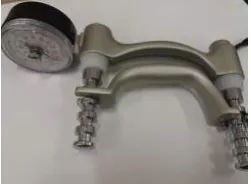
Fig. 5: Gripper with an ON-OFF switch.
Fig. 6: Stage2 experiments: gripping motions wearing the support.
push the gripper open. Hence its ON state indicated contraction of the muscles, and its OFF state indicated relaxation. This provided a ground truth during the following experiments. It was attempted to keep the grip force used as low as possible, just about exceeding the resistive torque of the spring, 2.10∗10−5Nm, with
stiff-ness 0.6582Nmm/rad and the switch whose maximum operating force is 0.25N. With regards to elbow flexion, monitoring of the bicep/tricep muscles will be required; therefore, the brace will be worn on the upper arm with the sensors positioned as during gripping experiments.
Interface of both the sensors and the microswitch was done using the Arduino UNO board and the data was transmitted through serial connection to MATLAB.
C. Stage3
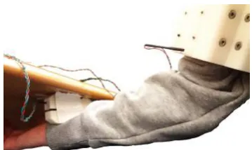
Finally, the third stage of experiments involved test-ing the concept on elbow flexion. The brace was po-sitioned on the upper arm to detect muscle activity in the bicep/tricep area. The gripper with the switch was attached on the underside of a table with the arm supported just underneath. As the elbow flexes and the forearm is raised the switch closes, Fig. 7. The two gripper handles were constrained at about 10mm apart, just enough to keep the switch open. To close the switch an average weight person would have to surpass the 0.113Nm torque needed to raise their 1.149kg forearm, as well as the 0.25N required to close the switch.
[image:4.595.345.525.101.208.2]The sensors were in proximity to the bicep (sensor1) and tricep muscles (sensor2). The forearm was resting on an arm-rest at about a 90◦ angle, just below the bottom of the gripper. Precautions had to be taken such the bicep was the one working to close the switch and not the flexor carpi radialis/ulnaris (wrist flexing muscles).
Fig. 7: Upper arm experiments, supported forearm closes switch during elbow flexion.
III. EXPERIMENTS
A. Proof of Concept
In this first stage, experiments were performed with the forearm muscles relaxed or contracted at certain pre-determined points in time. The forearm, rested on a table, placed inside the brace to which the sensors were attached with the palm facing upwards. With the conclusion of each experiment the forearm was removed from the support, therefore varying the sensor contact points with it. The upper arm and shoulder were kept relaxed throughout. Body position/posture changes were also performed without actively tensing the arm to find out whether the FSR signal patterns emerge could in-terfere with state recognition, whether the muscles were contracted or not. Visual inspection of the full data signal indicates certain patterns at the instances where there is a change in tension, Fig. 8. The forearm placement, its shape and weight and exerted force, would affect the contact forces between the sensors and the forearm; the higher the grip strength the contact force variations and hence the voltage reading changes.
0 5 10 15 20 25
Time (s) 1
1.5 2 2.5 3 3.5
Voltage (V)
[image:4.595.85.284.190.315.2]FSR Sensor Readings
Fig. 8: Proof-of-concept experiment; sensor2 readings during muscle contraction/relaxation in the forearm.
[image:4.595.334.541.542.645.2]0 5 10 15 20 25 30 35 40 Time (s)
0 2 4 6 8 10
Force (N)
Contact Force and Switch State
0 0.2 0.4 0.6 0.8 1
Switch State: 1=Tension, 0=Rest
[image:5.595.70.288.103.207.2]Sensor1 Sensor2 Switch State
Fig. 9: Plot of sensor2 detected forces and microswitch data indicating the state of the arm.
0 5 10 15 20 25 30 35 40
Time (s) 0
0.02
Force Change (N/s)
Force Derivative and Switch State
0 0.5 1
Switch State: 1=Tension, 0=Rest
Sensor1Derivative Sensor2Derivative Switch State
Fig. 10: Force derivatives of sensor1 and sensor2. The former barely records any changes.
rise of 1.15V (from 1.35 to 2.5V) which corresponds to contact force change of 0.52N (from 1.48N to 2N).
As the hand grips the dynamometer the flexor dig-itorum contracts while extensor digdig-itorum (posterior forearm compartment) relaxes completely; this causes a decrease in the contact force between the posterior part of the arm and sensor2. With the chosen forearm orientation, contact with sensor1 was minimal and hence not detectable.
B. Intent Recognition: Forearm
With the conclusion of these proof-of-concept exper-iments, it was clear that the sensor system was sensi-tive enough to detect changes between the arm and its brace when grip strength was limited to 19.6N. Hence, the second stage experiments commenced where sensor readings and switch state, providing a ground truth, were recorded. State prediction was performed and the accuracy of the results was determined using unit testing. By inspection there were no discernible contact force changes on sensor1, Fig. 10. This was expected, as its contact with the forearm was weak, hence sensor2 read-ings were the ones analysed, Fig 9. As seen in Fig. 10, where force changes are presented, large gradient changes hint towards a change of state. Negative gradients in-dicate muscle contraction of the gripping muscles, Fig 1, which causes the posterior part of the forearm and the sensor to loose contact. Following that, increasing contact forces indicate return to the initial state.
An algorithm was developed to classify the state of the forearm, whether it is ‘at rest’(muscle relaxation)
5 10 Time (s)15 20 25
0 0.5 1
Switch State: 1=Tension, 0=Rest
State Prediction
10
Force (N)
Recorded State Predicted State Sensor1 Contact Force
(a)
5 10 15 20 25 30
Time (s) 0
0.5 1
Switch State: 1=Tension, 0=Rest
State Prediction
5
Force (N)
Recorded State Predicted State Sensor1 Contact Force
[image:5.595.329.549.115.391.2](b)
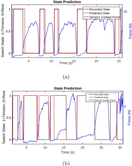
Fig. 11: Examples of predicted state, during gripping, when the algorithm is run against sensor readings along with the actual state.
or tensing (muscle contraction). The binary classification algorithm developed determines the state by looking at the emerging signal features, such as large step changes in gradient and their direction with respect to the baseline as well as previous tendencies. The accuracy is then determined by comparing the algorithm output to the microswitch state recorded. The algorithm focuses on the patterns that emerge with every new, incoming data set; aiming for state change detection within 1s. The initial state is always assumed to be ‘at rest’and a baseline value is thus determined. The algorithm parameters were hard-coded and so calibration was necessary, ??. Calibration was also performed during the preprocessing of the data; this included the use of a moving average filter to reduce noise which also introduced a time delay of 0.12s.
[image:5.595.66.291.257.363.2]input : sensor reading
output: State
while serialConnection == truedo
state(i)=state(i-1);
if dV(i) > dVThr AND DistFromBaseln=>increases AND return==0 then
if V(i) > V(i-1)then
incr++; UpTend = true;
else
decr++; DownTend = true;
end
if DistFromBaseln > maxDistBaseln thenmaxDistBaseln = DistFromBaseln;
else if dV > dVThr AND DistFromBaseln=>decreases AND state==1 then /* tension-to-rest */
return++;
if return > rThr AND (DistFromBaseln/maxDistBaseln) < ReturnThr then
returningTend = true; state = 0; maxDistBln = 0; incr = 0; decr = 0;
else
incr = 0; decr = 0;
end
if ((incr > UpperThr) AND (decr < LowerThr)) OR ((decr > UpperThr) AND incr < (LowerThr)) then
/* contraction prediction */
state = 1;
end
if UpTend==false AND DownTend==false AND state(i-1)==1 thenstate = 1; incr = 0; decr = 0;
/* during tension */
if returnTendancy==true AND dV(i) < dVThr then
returnEnd++;
if returnEnd > rThre then
returnTendancy = false; return = 0; state = 0;
end end
if dV(i) < dVThr AND state==0 then /* baseline value update */
b++;
if b > BaseLnThr thenBaseln = V(i);
end
Algorithm 1:Algorithm overview
During the experiments the gripper had to move quasi-statically but that increased the delay between muscle contraction and movement reaction detection. This was evident in certain cases where the detection of tension happened prior to the switch indication. An occurrence of this can be seen in Fig. 11a where the first tension period is detected 0.10s before there is any indication of it from the switch state. By observation and looking at the signal turning points, the maximum delay that arises is estimated to be at 0.455s. This could be addressed by using a continuous gripping force measurement device; this would enable detection the instant there was move-ment in the hand.
When the algorithm successfully detected the state change, the maximum delay, over all experiments the algorithm was tested against, was 0.6s. At the absence of key patterns from the waveform??the algorithm will delay making a decision until it is certain of such change.
In about a fifth of the data points the forearm intention
to move was wrongly classified due to delays in detecting muscle relaxation and early detections of tension when the switch state change is delayed compared to the onset of tension in the arm. One cause of false positives though that could cause issues would be the complete failure to detect the arm has gone back to rest; such as in Fig. 11b, at t=23.24s.
C. Intent Recognition: Upper Arm
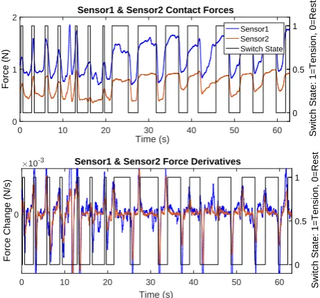
Stage3 involved testing the motion intent detection system performance during elbow flexion. As mentioned earlier, II-C, to experiment with elbow movement the arm brace was fitted on the upper arm. Similar contact force patterns emerged here 12, during elbow flexion, as previously in the lower arm when gripping was per-formed.
0 10 20 30 40 50 60
Time (s)
0 1 2
Force (N)
Sensor1 & Sensor2 Contact Forces
0 0.5 1
Switch State: 1=Tension, 0=Rest
Sensor1 Sensor2 Switch State
0 10 20 30 40 50 60
Time (s)
0
Force Change (N/s)
10-3 Sensor1 & Sensor2 Force Derivatives
0 0.5 1
[image:7.595.63.294.109.324.2]Switch State: 1=Tension, 0=Rest
Fig. 12: Sensor1 and sensor2 recorded contact forces in the upper arm during elbow flexion.
20 30 40 50 60 70 80 90 100 110
Time (s)
0 0.2 0.4 0.6 0.8 1
Switch State: 1=Tension, 0=Rest
State Prediction
1 1.5 2 2.5
Force (N)
Recorded State Predicted State Sensor1 Contact Force
Fig. 13: Elbow flexion state prediction using the adapted algorithm.
bicep and the tricep vary in a similar manner; with the sensor in proximity to the bicep recording changes of slightly higher magnitudes, by an average of 20%.
The classification algorithm parameters were tuned accordingly for use on the forearm and the results with an average accuracy of 83.9%. As Fig. 13 illustrates, the adapted algorithm was successful at correct state predic-tion with higher confidence levels than gripping. During this set of experiments, there was slight movement of the support, and sometimes even a small rotation, as the bi-cep contracted. This affected the accuracy of data acqui-sition as the point of contact of the sensor with the upper arm was shifting, influencing classification. Nonetheless, the state classification accuracy was improved compared to gripping which is a more complex movement involving a greater number but smaller muscles.
IV. DISCUSSION
In this pilot study on the use of tactile sensing for motion intent recognition in stroke patients the results were promising for the development of a reliable, quick detection system, as part of an actuated device. Evidence suggests that by using two FSR sensors we are able to detect low activations of muscles, when using no more than 6.45% of average nominal strength. Detection occurs within 1s in both the upper and lower arm. The accuracies of this pilot study system when classifying the state of the arm/hand averaged at 80%. Mimicking re-habilitation therapist practices we are identifying muscle contraction changes to guide the limb through a motion.
A. Limitations
There were some limitations and shortcomings in these first experiments. Firstly, there was a visible delay between the initiation of the movement and and the change in the microswitch state in some cases; this created an uncertainty in the results as it is not possible to know the exact time a state change took place. Hence, instead of a binary gripper, we will introduce a continuous gripping force measurement device. Furthermore, this system has not yet been tested on stroke survivors. Nonetheless, an attempt was made at setting some force limitations during experimentation based on the minimal strength data for stroke patients. Whether these could be sensed as well with a thicker forearm and weaker muscles is yet to be seen. Furthermore, the slight movement of the ‘enclosure’during Stage3 experiments affects the trustworthiness of the results; thus while keeping the sensors attached on solid surfaces they will be held together on the arm using a tight fitting arm band. With a hard-coded feature algorithm there are limitation when it comes to generalisation. Alternatively, a supervised learning, classification algorithm will be trained on the features using the experimental data.
V. CONCLUSIONS AND FUTURE WORK
Despite the aforementioned limitations the results in this pilot study were promising. Following the improve-ment of the sensing technology, future work will see the actuation of an upper limb brace and its use to support the elbow flexion/extension motion using a tactile sens-ing driven controller. The potential in the use of more than two FSR sensors will be studied and integration with EMG will be looked into as well.
ACKNOWLEDGMENT
[image:7.595.58.292.383.511.2]References
[1] Jack A Adams. “A closed-loop theory of motor learning”. In:Journal of motor behavior 3.2 (1971), pp. 111–150.
[2] D S Andreasen et al. “Exoskeleton for forearm pronation and supination rehabilitation”. In: En-gineering in Medicine and Biology Society, 2004. IEMBS’04. 26th Annual International Conference
of the IEEE. Vol. 1. IEEE. 2004, pp. 2714–2717.
[3] M. Barsotti et al. “A full upper limb robotic ex-oskeleton for reaching and grasping rehabilitation triggered by MI-BCI”. In:IEEE International
Con-ference on Rehabilitation Robotics. Vol. 2015-Septe.
2015, pp. 49–54.
[4] Massimo Bergamasco et al. “Preliminary results of BRAVO project: Brain computer interfaces for robotic enhanced action in Visuo-motOr tasks”. In:
IEEE International Conference on Rehabilitation
Robotics. 2011.
[5] Claudio Castellini and Risto Koiva. “Using a high spatial resolution tactile sensor for intention detec-tion”. In:2013 IEEE 13th International Conference
on Rehabilitation Robotics (ICORR). IEEE, June
2013, pp. 1–7.
[6] Erina Cho et al. “Force Myography to Control Robotic Upper Extremity Prostheses : A Feasi-bility Study”. In: Frontiers in Bioengineering and
Biotechnology 4.March (2016), pp. 1–12.
[7] Carlo J De Luca. “The use of surface electromyo-graphy in biomechanics”. In: Journal of applied
biomechanics 13.2 (1997), pp. 135–163.
[8] Richard M Dodds et al. “Grip strength across the life course: normative data from twelve British studies”. In: PloS one 9.12 (2014), e113637. [9] Dario Farina et al. “The extraction of neural
in-formation from the surface EMG for the control of upper-limb prostheses: Emerging avenues and chal-lenges”. In:IEEE Transactions on Neural Systems
and Rehabilitation Engineering 22.4 (2014).
[10] Ranathunga Arachchilage Ruwan Chandra Gopura, Kazuo Kiguchi, and Yang Li. “SUEFUL-7: A 7DOF upper-limb exoskeleton robot with muscle-model-oriented EMG-based control”. In:
2009 IEEE/RSJ International Conference on
Intelligent Robots and Systems. 2009.
[11] Interlink Electronics. “Interlink Electronics FSRR
Force Sensing Resistors R”. In: (2016), pp. 1–33.
[12] Interlink Electronics. “Interlink Electronics FSRR
Force Sensing Resistors R”. In: (2016), pp. 1–33. [13] Dean M. Karantonis et al. “Implementation of a
real-time human movement classifier using a triax-ial accelerometer for ambulatory monitoring”. In:
IEEE Transactions on Information Technology in
Biomedicine 10.1 (2006), pp. 156–167.
[14] Kazuo Kiguchi, Ryo Esaki, and Toshio Fukuda. “Development of a wearable exoskeleton for daily
forearm motion assist”. In:Advanced Robotics19.7 (2005), pp. 751–771.
[15] Kazuo Kiguchi and Yoshiaki Hayashi. “An EMG-based control for an upper-limb power-assist ex-oskeleton robot”. In: IEEE Transactions on Sys-tems, Man, and Cybernetics, Part B (Cybernetics)
42.4 (2012), pp. 1064–1071.
[16] Kazuo Kiguchi et al. “An exoskeleton for human elbow and forearm motion assist”. In: Intelligent Robots and Systems, 2003.(IROS 2003).
Proceed-ings. 2003 IEEE/RSJ International Conference on.
Vol. 4. IEEE. 2003, pp. 3600–3605.
[17] Risto Koiva et al. “Shape conformable high spa-tial resolution tactile bracelet for detecting hand and wrist activity”. In: 2015 IEEE International
Conference on Rehabilitation Robotics (ICORR).
IEEE, Aug. 2015, pp. 157–162.
[18] T A Kuiken, M M Lowery, and N S Stoykov. “The effect of subcutaneous fat on myoelectric signal amplitude and cross-talk”. In: Prosthetics
and orthotics international 27.1 (2003).
[19] Charles Long et al. “Intrinsic-extrinsic muscle con-trol of the hand in power grip and precision han-dling”. In: J Bone Joint Surg Am 52.5 (1970), pp. 853–867.
[20] Peter Lum et al. “Robotic Devices for Movement Therapy After Stroke: Current Status and Chal-lenges to Clinical Acceptance”. In:Topics in Stroke
Rehabilitation 8.4 (Jan. 2002), pp. 40–53.
[21] Gabrielle McHugh and Ian D. Swain. “A com-parison between reported and ideal patient-to-therapist ratios for stroke rehabilitation”. In:
Health 05.06 (2013).
[22] Shunji Moromugi et al. “Muscle stiffness sensor to control an assistance device for the disabled”. In:
Artificial Life and Robotics 8.1 (2004), pp. 42–45.
[23] NICE. Stroke rehabilitation in adults | Guidance
and guidelines.
[24] Kyuichi Niizeki et al. “Unconstrained cardiorespi-ratory and body movement monitoring system for home care”. In:Medical and Biological Engineering
and Computing 43.6 (2005), pp. 716–724.
[25] OMRON ELECTRONIC COMPONENTS.
Mi-croswitch D2FS-FL-N. 2016.
[26] Joel C Perry, Jacob Rosen, and Stephen Burns. “Upper-limb powered exoskeleton design”. In:
IEEE/ASME transactions on mechatronics 12.4
(2007), p. 408.
[27] Practitioner Supplies.Hand Dynamometer. 2017. [28] Vikram Ravindra and Claudio Castellini. “A
com-parative analysis of three non-invasive human-machine interfaces for the disabled”. In: Frontiers
in Neurorobotics 8.JAN (2014).
[30] S H Roy et al. “Electro-mechanical stability of surface EMG sensors”. In: Medical {&} Biological
Engineering {&} Computing 45.5 (2007).
[31] Royal College of Physicians. “National clinical guideline for stroke Prepared by the Intercollegiate Stroke Working Party”. In: (2016).
[32] A Sunderland et al. “Arm function after stroke. An evaluation of grip strength as a measure of recovery and a prognostic indicator.” In: Journal
of neurology, neurosurgery, and psychiatry 52.11
(1989).
[33] Mohsin I Tiwana, Stephen J Redmond, and Nigel H Lovell. “A review of tactile sensing technologies with applications in biomedical engineering”. In:
Sensors and Actuators A: physical 179 (2012).
[34] Tyromotion. DIEGO Arm-Shoulder Rehabilitation
Device. 2016.url: http://tyromotion.com/en/
products/diego.
[35] Michael Wininger, Nam-Hun Kim, and William Craelius. “Pressure signature of forearm as pre-dictor of grip force.” In: Journal of rehabilitation
research and development45.6 (2008), pp. 883–892.
![Fig. 1: The flexor digitorum profundus (FDP), flexordigitorum superficialis (FDS) and flexor pollicis longusmuscles (FPL) - in all three diagrams the posteriorcompartment of the forearm is shown[36].](https://thumb-us.123doks.com/thumbv2/123dok_us/599757.560033/2.595.319.555.525.642/digitorum-profundus-exordigitorum-supercialis-pollicis-longusmuscles-diagrams-posteriorcompartment.webp)