Machinability of Short Potassium Titanate Fiber Reinforced AC4A
Aluminum Alloy Composite
Kazunori Asano, Hiroyuki Yoneda and Yasuyuki Inui
Department of Mechanical Engineering, School of Science and Engineering, Kinki University, Higashiosaka 577-8502, Japan
Aluminum alloy composites reinforced with short potassium titanate fibers were fabricated by squeeze casting, and the effect of the fiber reinforcement on the machinability of the alloy under various cutting conditions were investigated. The fibers were randomly arranged in the alloy matrix, and no agglomeration of the fibers or porosity was observed. Although the cutting force of the AC4A alloy decreased as the cutting speed increased, that of the composites little changed even though the cutting speed increased. When the cutting speed was 50 m/min, the cutting force of the AC4A alloy significantly decreased due to the fiber reinforcement. When the cutting speed was 100 and 150 m/min, the cutting force of the composites was equivalent to or less than that of the AC4A alloy. The variation in the fiber volume fraction only slightly affected the cutting force values of the composites. The roughness of the machined surface of the AC4A alloy increased as the feed rate increased, and decreased as the cutting speed increased. The fiber reinforcement diminished the variation in the roughness due to the feed rate and cutting speed. When the feed rate was high, the roughness of the composite having a high fiber volume fraction was almost equivalent to the theoretical roughness. This indicates that the fiber reinforcement suppresses the formation of the built-up edge. The machined surface and chip forms indicated that the fibers in the composite facilitated the shear deformation of the chips because the fibers were easily sheared by the cutting. These results lead to the conclusion that the machinability of the composite is superior to that of the AC4A alloy.
[doi:10.2320/matertrans.MER2008180]
(Received June 5, 2008; Accepted July 29, 2008; Published September 25, 2008)
Keywords: metal matrix composite, aluminum, potassium titanate fiber, squeeze casting, microstructure, machinability
1. Introduction
The use of aluminum alloys has increased in many industrial applications because the reduction in the weight and size of the products, such as automobile parts, has recently been promoted. These applications often require the improvement in the strength, rigidity, heat resistance and wear resistance of the aluminum alloy. To satisfy these requirements, the reinforcement of the aluminum alloy with ceramic fibers or particles has been presented. The aluminum alloy composites reinforced with the ceramic fibers or particles have been not only studied fundamentally but also made by way of trial or put into practical use.1)However, there is a concern about a decrease in machinability of the aluminum alloy by reinforcing with ceramics, because ceramics are generally difficult to machine. Therefore, it is very important to clarify the machinability of the composites. To develop a machinable aluminum alloy composite having low thermal expansion rate, we have noticed the potassium titanate as the reinforcement because it has low thermal expansion and hardness. Although several investigations have been conducted on the aluminum alloy composites reinforced with the potassium titanate whisker,2–6) the whiskers are considered harmful to the respiratory organs.7) The short potassium titanate fiber, having greater diameter and length than the whisker, was developed to reduce this concern.8) Based on these findings, we fabricated AC4A aluminum alloy composites reinforced with the short potas-sium titanate fibers by squeeze casting, and clarified that the thermal expansion coefficient of the composite was lower than that of the AC4A aluminum alloy.9)
In the present study, short potassium titanate fiber reinforced AC4A aluminum alloy composites were fabricat-ed, and the effects of the fiber volume fraction in the composite and cutting conditions on the machinability were
clarified by measuring the cutting resistance and observing the machined surface and chip forms.
2. Experimental Procedure
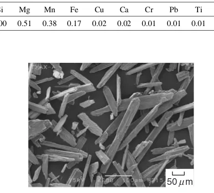
[image:1.595.318.527.583.772.2]JIS-AC4A aluminum alloy with its chemical composition shown in Table 1 was used as the matrix metal. Short potassium titanate fibers (TXAX-A, Kubota Co.) were used as the reinforcement. Figure 1 is a SEM micrograph of the fibers, showing that their average diameter is 30mm and average length is 150mm. The chemical composition and properties of the short potassium titanate fiber8)are shown in Table 2. The Vickers hardness of the fiber is 160–200 HV, which is considerably lower than that of alumina (1500– 2000 HV10)).
Table 1 Chemical composition of AC4A aluminum alloy (mass%).
Si Mg Mn Fe Cu Ca Cr Pb Ti Al
9.00 0.51 0.38 0.17 0.02 0.02 0.01 0.01 0.01 Bal.
50µm
Fig. 1 SEM micrograph of potassium titanate fibers.
The preforms were fabricated as follows. The fibers were dispersed using careful agitation in an aqueous medium containing polyvinyl alcohol (PVA) as the organic binder and Al2O3sol as the inorganic binder. Dewatering was conducted by press forming, followed by drying at 373 K for 3 hours to drive off any residual free water and to obtain the strength due to the PVA. After drying, the preform was sintered at 1173 K for 1 hour to burn off the PVA and generate the strength due to the presence of the Al2O3binder. The preform had 50 mm diameter and 20 mm thick. The preforms re-spectively contained 25, 35 and 45 vol% of the fiber. In the preform, the fibers were oriented in a random configuration. The composite was fabricated by squeeze casting. The preform was horizontally placed in the permanent mold, and the AC4A alloy melt (1073 K) was poured into the mold (673 K). Pressure (40 MPa) was quickly applied and main-tained until the solidification was complete.
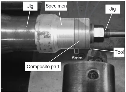
The test piece of 40 mm diameter was machined from the composite, and then the machinability was examined by cutting the outside surface of the test piece with a diamond cutting tool. Figure 2 shows the appearance of a test piece clamped in a lathe. The cutting conditions are shown in Table 3. The cutting resistances (cutting force and feed force) were measured with the elastic disc type tool dynamometer, and roughness of the machined surface was measured with the surface profiler. The machined surface, cross section and chip forms of the specimens were observed.
3. Results and Discussion
3.1 Microstructure and hardness of composites
The macrostructure of the vertical cross-section of the
composites indicated that the melt infiltration was perfectly accomplished with no observable defects. The height of the composite was approximately 20 mm, which is almost equal to that of the preform before the infiltration. This indicates that the infiltration was successful without any preform contraction or deformation.
Figure 3 shows the optical micrographs of the parallel section of the composites. The dark phases observed in the micrographs are the short potassium titanate fibers. No agglomeration of the fibers or porosity is observed in the composite, indicating that the melt infiltration into the fiber preform was perfectly accomplished. The fibers were in a random arrangement. The matrix of every composite was
[image:2.595.322.532.72.225.2]aluminum (light area observed in the micrographs) in which the fine eutectic silicon particles were dispersed. Table 2 Properties of short potassium titanate fiber.8Þ
Composition K2O6TiO2
Average diameter (mm) 30
Average length (mm) 150
Density (Mg/m3) 3.53
Melting point (K) 1583{1623
Thermal conductivity (W/(mK)) 1.7 (at 1003 K) Thermal expansion coefficient
(106/K) (293–373 K) 6.8
Hardness (HV) 160{200 Composite part
Specimen Jig
Jig
Tool
[image:2.595.52.292.83.193.2]Fig. 2 Appearance of a test piece clamped in a lathe.
Table 3 Cutting conditions.
Cutting tool PCD
Rake angle 5
End cutting edge angle 15
Nose radius (mm) 0.8
Cutting speed (m/min) 50, 100, 150
Cutting depth (mm) 1.0
Feed rate (mm/rev) 0.10, 0.15, 0.20
Cutting fluid None
Vf=45vol%
Vf=35vol%
Vf=25vol%
100µm
Fiber
Eutectic Si
[image:2.595.309.549.285.386.2] [image:2.595.108.488.620.767.2]Table 4 shows the Vickers hardness of the AC4A alloy and composites. It shows that the hardness increased as the fiber volume fraction (hereinafter Vf) increased. The Vickers hardness of the composite with 45 vol% fiber was 138 HV, which is not very high due to the low hardness of the fiber.
3.2 Machinability of composites
[image:3.595.315.542.76.167.2]Figure 4 shows the variation in the cutting forceFcduring the cutting of the AC4A alloy. When the cutting speedwas 50 m/min, the width of the serrations (variation inFc) at feed rate f of 0.2 mm/rev was greater than that of 0.1 mm/rev (Fig. 4(a)). Although a similar tendency was recognized when the cutting speed was 150 m/min, the width of the serrations was smaller than that when the cutting speed was 50 m/min (Fig. 4(b)). Figure 5 shows the variation in Fc during the cutting of the composite (Vf ¼45vol%). Under the same cutting condition, the averageFcof the composite was smaller than that of the AC4A alloy shown in Fig. 4.
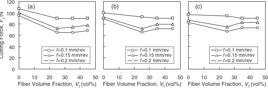
Figure 6 shows the effect of Vf, feed rate f, and cutting speed on the Fc of the AC4A alloy and composites. As shown in Figs. 4 and 5, since the serrations (variation inFc) were observed during the cutting, the mean values ofFcwere picked up in Fig. 6. At every cutting speed,Fcincreased as the feed rate increased. This is due to the increase in the cutting area by increasing the feed rate. At every feed rate,
Fcof the AC4A alloy (Vf ¼0vol%) slightly decreased as the cutting speed increased. However, theFc of the composites (Vf ¼25, 35 and 45 vol%) little changed even if the cutting speed increased. When the cutting speed was 50 m/min, the Fcof the composites was lower than that of the AC4A alloy (Vf ¼0vol%); reinforcement with the fiber decreased the Fc by 20–30 N, as shown in Fig. 6(a). For the composites (Vf ¼25, 35 and 45 vol%), the variation inVf only slightly affected theFc. When the cutting speed was 100 or 150 m/ min, the decrease in Fcby the fiber reinforcement was low compared to when the cutting speed was 50 m/min. The decrease inFcby the fiber reinforcement is probably due to the fact that the existence of the fibers facilitates the shear deformation of the chips.
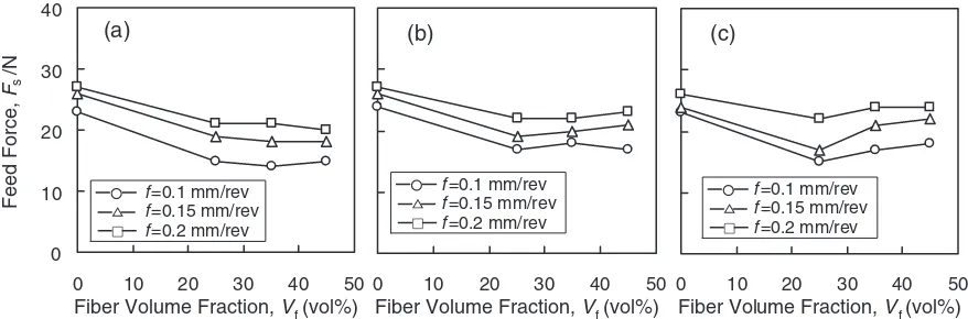
Figure 7 shows the effect of Vf, feed rate f, and cutting speed on the feed force Fs of the AC4A alloy and composites. For all the specimens, Fs was lower than Fc (Fig. 6). The variation inFsvalues due to the variation inVf or the cutting conditions was similar to that inFc.
Figure 8 shows the effect of Vf, feed rate f, and cutting speed on the surface roughness (maximum height) Rz of the AC4A alloy and composites. For the AC4A alloy (Vf ¼
0vol%), Rz increased as the feed rate increased for every cutting speed, and decreased as the cutting speed increased. The variation in Rz of the composites (Vf ¼25, 35 and 45 vol%) due to the increase in the cutting speed or feed rate was small when compared to that of the AC4A alloy. The theoretical roughness can be geometrically obtained from the nose radius of the cutting tool and feed rate.11) It can be written as
Table 4 Hardness of AC4A aluminum alloy and composites.
Vf(vol%) 0 25 35 45
Hardness (HV) 65 89 118 138
40 60 80 100 120
f= 0.1mm/rev
f= 0.2mm/rev
Cutting Force,
Fc
/N
f= 0.1mm/rev
f= 0.2mm/rev
1
0 0 1
Feed Length, L/mm Feed Length, L/mm
(a) (b)
4 3
2 2 3 4
Fig. 4 Variation in cutting force during cutting of AC4A alloy at the cutting speed of (a) 50 m/min and (b) 150 m/min. f in the figure represents the feed rate.
40 60 80 100 120
f= 0.1mm/rev
f= 0.2mm/rev
f= 0.1mm/rev
f= 0.2mm/rev
Cutting Force ,
Fc
/N
1
0 0 1
Feed Length, L/mm Feed Length, L/mm
(a) (b) 4 3 2 4 3 2
Fig. 5 Variation in cutting force during cutting of composite with 45 vol% fiber at the cutting speed of (a) 50 m/min and (b) 150 m/min. f in the figure represents the feed rate.
0 0 0 20 40 60 80 100 120 0 Cutting Force, Fc /N
f =0.1 mm/rev
f =0.15 mm/rev
f =0.2 mm/rev
f =0.1 mm/rev
f =0.15 mm/rev
f =0.2 mm/rev
f =0.1 mm/rev
f =0.15 mm/rev
f =0.2 mm/rev
(a) (b) (c)
Fiber Volume Fraction, Vf(vol%) Fiber Volume Fraction, Vf(vol%)
Fiber Volume Fraction, Vf(vol%) 50 40 30 20
10 10 20 30 40 50 10 20 30 40 50
[image:3.595.48.289.80.230.2] [image:3.595.78.520.611.756.2]Rth¼ f 2
8r ð1Þ
whereRthis the theoretical roughness andris the nose radius. Generally, the surface roughness value is larger than Rth because the formation of the built-up edge and the accretions roughen the machined surface. In addition, the increase in the cutting speed reduces the built-up edge because the increase in the cutting speed raises the surface temperature.
Values ofRthcalculated using eq. (1) are shown in Fig. 8. For the AC4A alloy (Vf ¼0vol%), the values of Rz approached that of Rth as the cutting speed increased. The relationship betweenRzandRthof the composites (Vf ¼25, 35 and 45 vol%) was different with that of the AC4A alloy. Particularly, for the composite with 45 vol% fiber, Rz was close to Rth when the feed rate was 0.2 mm/rev for every cutting speed. This result indicates that the fibers in the composite suppress the formation of the built-up edge even at a low cutting speed.
Figure 9 shows SEM micrographs of the machined surfaces of the AC4A alloy and composites (¼50m/ min). On the machined surfaces of the AC4A alloy, plastic flow is pronounced as the feed rate f increased. In contrast, the machined surfaces of the composites (Vf ¼25 and 45 vol%) are not apparently changed by the feed rate. An
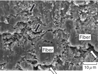
enlarged view of the machined surfaces of the composite with 45 vol% fiber is shown in Fig. 10 (f ¼0:2mm/rev). Although impressions are observed at the fiber-matrix interfaces (indicated by ‘‘ ’’ in the figure), the machined surfaces of the fibers in the composite are smooth, indicating that the fibers facilitated the shear deformation during the cutting. Because similar impressions are also observed in the matrix (indicated by ‘‘ ’’), it is conjectured that the interfacial exfoliation by the cutting is not serious. The cross-section near the surface of the composites machined under this condition is shown in Fig. 11, indicating no interfacial exfoliation.
Figure 12 shows the chip forms of the AC4A alloy and composites obtained when the cutting speedis 50 m/min. At every feed rate, continuous chips were formed after cutting the AC4A alloy, while sheared or serrated chips were formed after cutting the composites. In addition, the chips were shorter whenVf was large.
The tendencies observed in Figs. 9–12 were also observed when the cutting speed was 100 and 150 m/min. It is reported that dispersing the hard phases in the aluminum alloy facilitates the shear deformation of the alloy due to the stress concentration at the hard phase during the cutting.12,13)The results occurred in the present study can be expressed by the same mechanism; the fibers in the composite facilitate the
0 0
0 10 20 30 40
0
Feed Force,
Fs
/N
f=0.1 mm/rev
f=0.15 mm/rev
f=0.2 mm/rev
f=0.1 mm/rev
f=0.15 mm/rev
f=0.2 mm/rev
f=0.1 mm/rev
f=0.15 mm/rev
f=0.2 mm/rev
Fiber Volume Fraction, Vf (vol%) Fiber Volume Fraction, Vf (vol%)
Fiber Volume Fraction, Vf (vol%)
(a) (b) (c)
50 40 30 20
10 10 20 30 40 50 10 20 30 40 50
Fig. 7 Effect of fiber volume fraction, feed ratef, and cutting speedon feed force of AC4A alloy and composites ((a)¼50m/min, (b)
¼100m/min and (c)¼150m/min).
0 4 8 12
0
Maximum Height,
Rz
/
m
µ
f=0.1 mm/rev, Rth =1.56 m
m
m µ µ
µ
f=0.15 mm/rev, Rth =3.52
f=0.2 mm/rev, Rth =6.25
f=0.1 mm/rev
f=0.15 mm/rev
f=0.2 mm/rev
Fiber Volume Fraction, Vf (vol%) Fiber Volume Fraction, Vf (vol%) Fiber Volume Fraction, Vf (vol%)
(a) (b) (c)
50 40 30 20
10 0 10 20 30 40 50 0 10 20 30 40 50
[image:4.595.78.517.74.219.2] [image:4.595.83.516.275.433.2]shear deformation of the chips because the fibers are easily sheared by the cutting.
4. Conclusions
Short potassium titanate fiber reinforced AC4A aluminum alloy composites were fabricated, and the machinability and the cutting mechanisms of the composites were investigated. The following conclusions were obtained.
(1) The fibers were randomly arranged in the alloy and no agglomeration of the fibers or porosity was observed in the composites. Although the hardness increased as the fiber volume fraction increased, the hardness of the composite with 45 vol% fiber was 138 HV, which was not very hard.
(2) The cutting force Fc of the AC4A alloy slightly decreased as the cutting speed increased, while Fc of the composites little changed even if the cutting speed increased. Under the same condition, Fc of the
composites was equivalent to or less than that of the AC4A alloy. Specifically, the decrease inFcby the fiber reinforcement was pronounced when the cutting speed was 50 m/min. The variation in the fiber volume fraction only slightly affectedFcof the composite. (3) For the AC4A alloy, the surface roughnessRzincreased
as the feed rate increased for every cutting speed, and decreased as the cutting speed increased. The change in Rzof the composites was low when the cutting speed or the feed rate increased, compared to that of the AC4A alloy. For the composite with 45 vol% fiber, Rz was close to the theoretical roughness when the feed rate was 0.2 mm/rev for every cutting speed. This result indicates that the fibers in the composite suppress the formation of the built-up edge even at a low cutting speed.
(4) The machined surface and chip forms indicated that the fibers in the composite facilitated the shear deformation of the chips because the fibers were easily sheared by the cutting.
AC4A alloy Vf= 25vol% Vf = 45vol%
f= 0.1 mm/rev
f= 0.2 mm/rev
50µm
Fig. 9 SEM micrographs of machined surfaces of AC4A alloy and composites (¼50m/min).
Fiber
10µm
[image:5.595.65.534.71.308.2]Fiber
Fig. 10 Enlarged view of machined surfaces of composite (Vf¼45vol%,
¼50m/min,f ¼0:2mm/rev). Impressions are observed in the matrix (indicated by ‘‘ ’’) and fiber-matrix interfaces (indicated by ‘‘ ’’).
[image:5.595.326.525.351.495.2]25µm
Fig. 11 Cross-section of machined surface of composite (Vf¼45vol%,
[image:5.595.75.263.353.495.2](5) These results lead to the conclusion that the machi-nability of the composite is superior to that of the AC4A alloy.
Acknowledgement
We wish to thank the Kubota Co. for providing the short potassium titanate fibers.
REFERENCES
1) K. Asano and T. Noguchi: J. JFS78(2006) 96–105. 2) K. Suganuma: J. Jpn. Inst. Metals58(1994) 1213–1219.
3) H. Harada, Y. Kudoh, Y. Inoue and I. Tsuchitori: J. Jpn. Inst. Metals58 (1994) 69–77.
4) I. Tsuchitori and H. Fukunaga: J. Jpn. Inst. Metals56(1992) 333–341. 5) K. Suganuma, T. Fujita and K. Niihara: J. Jpn. Inst. Metals54(1990)
1422–1431.
6) Y. Nishida, T. Imai, M. Yamada, H. Matsubara and I. Shirayanagi: J. JILM38(1988) 515–521.
7) H. Yamato, A. Ohgami, I. Akiyama, T. Oyabu, Y. Morimoto, S. Ishimatsu, H. Hori, T. Higashi and I. Tanaka: Report of JAAST Meeting16(1994) 58.
8) Kubota Co.: Data sheet for TXAX (2005).
9) K. Asano, H. Yoneda and Y. Agari: J. JFS80(2008) 8–14.
10) Y. Nishida: Introduction to Metal Matrix Composites, (Corona Publishing, Tokyo, 2001) p. 142.
11) Ed. by Kikai Kosakugaku Henshu Iinkai:Kikai Kosakugaku(Sangyo Tosho, Tokyo, 2003) p. 148.
12) B. Yan and C. Wang: J. JILM43(1993) 187–192. 13) T. Saga and S. Ikeda: J. JILM41(1991) 264–269. Vf =45vol%
f=0.1 mm/rev
10mm f=0.15
mm/rev
f=0.2 mm/rev
[image:6.595.86.513.70.347.2]AC4A Vf =25vol% Vf =35vol%