Performance Assessment of Composite Structures: An Overview of Activities at
the University of Southampton
J. M. Dulieu-Barton, R. A. Shenoi, S. Quinn, J. I. R. Blake, S. W. Boyd
School of Engineering Sciences, University of Southampton, Highfield, Southampton, UK
Summary: The purpose of this extended abstract is to provide an overview of activities relating to performance assessments. The work described is wide ranging and not intended to provide a detailed account of any particular approach.
Introduction
Understanding the mechanical and physical behaviour of layered orthotropic material is an essential key step in performance assessment of composite structures and sandwich structures. At the University of Southampton, UK, work has been conducted in analytical, numerical and experimental techniques for damage assessment of composite materials and structures. Data-rich experimental mechanics techniques have been developed to assess damage using thermoelastic stress analysis (TSA) [1], vibration-based approaches [2-4] and acoustic emission. Alongside this advanced signal processing procedures have been devised to parameterise the data. Work has also concentrated on extracting the stresses and their distributions from complex structures to establish the failure mechanisms and make predictions of the component life [5-8], in particular adhesive joints, e.g. [9].
A range of composite materials have been studied but the main thrust is in applications relating to the marine industry and therefore the work described in this extended abstract will focus on glass reinforced polymer composites; although some recent work on full scale tests in carbon fibre Nomex honeycomb sandwich structure is also detailed. Multi-scale evaluations are described from the fibre matrix interaction to assessment of full scale structure. A key part of the work has been in devising measurement approaches that permit detailed information to be extracted from experimental data to allow comprehensive assessment of structures and materials: some key examples of this are provided. The work covers examples of experimental stress analysis and its use as a validation tool, fatigue damage assessments and applications to NDE. In evaluating performance a key consideration is the manufacturing process and parts of the extended abstract are devoted to the discussion on the effects of manufacturing and concurrent engineering. Finally some insight into through life assessments is provided. The extended abstract concludes with an overview of what the Southampton team regard as technical and scientific challenges facing the marine industry in the future.
Thermoelastic stress analysis of composite structures
field associated with a typical fibre/matrix composite is essentially discontinuous and on a micro scale cannot be considered homogeneous. The challenge has been to apply this technique to composite structures and obtain meaningful data related to the stresses.
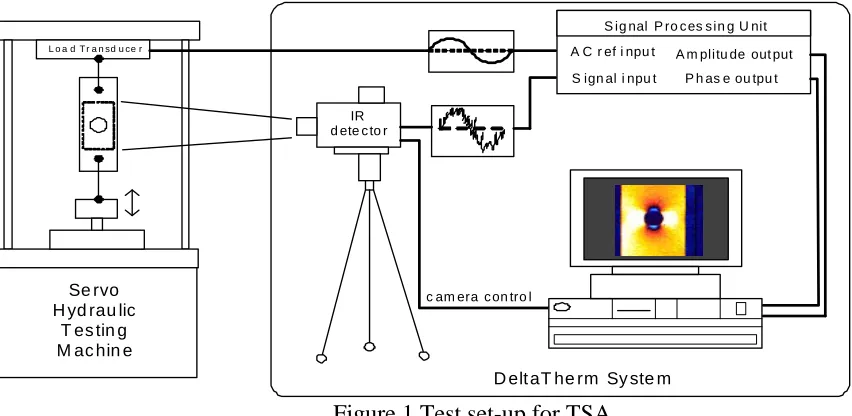
Se rvo H yd rau lic
T es tin g M ac hin e
L o a d T r a n sd u ce r
IR d ete c to r
D elt aT he rm Sy ste m
c am era c on tro l
S ig nal P ro c es s in g U nit A C r ef i npu t
S ign al i npu t
[image:2.612.77.503.112.320.2]A m plitu de out put P h as e ou tpu t
Figure 1 Test set-up for TSA
So far, the application of TSA to composite materials has focused on non-crimp, non-woven fibres, e.g. [10, 11]. In woven material, even under simple loading conditions such as uniaxial tension, the response will be non-uniform and dependent on the orientation of the weave. In general the heterogeneous nature of laminated composite materials produces a non-uniform thermoelastic response. Typically in laminates constructed from layers of unidirectional material, this non-uniformity is only present from lamina to lamina, i.e. through the thickness of the laminate. As the material properties are uniform within a single ply, thermoelastic measurements from the surface may assume orthotropic material properties. Therefore woven materials commonly used in shipbuilding provide an enormous challenge to TSA. Recent work [12] at high magnification on these materials has revealed that the stresses in the woven structure can be obtained using the technique, providing the possibility of identifying damage initiators in structure. A typical data set from a twill type weave is shown in Figure 2. Here the stress concentrations because of the crimp are revealed. It should also be noted that the weave dimension was about 0.5 mm. This means that in this data interaction at the fibre-matrix scale is being revealed, which has not been seen previously, experimentally.
Figure 2 Thermoelastic data from a woven glass epoxy material
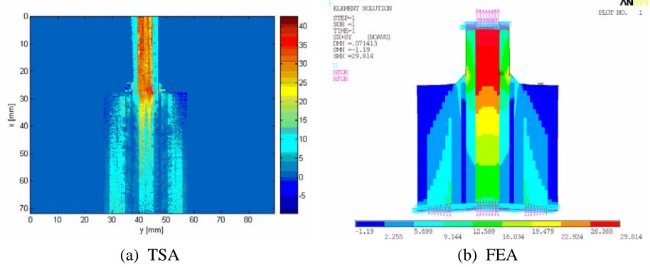
Further work is continuing on the determination of through thickness thermoelastic properties for the constituent materials in the pultruded lay-up. This data is essential for the application of the modelling approach for adhesively bonded lap joints where the load transfer is in the through thickness direction. Initial results indicate that the assumptions made as shown in Figure 4 bound the actual results.
[image:3.612.79.536.296.484.2](a) TSA (b) FEA
Figure 3 TSA and FEA stress data for a double lap joint in tension
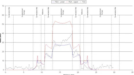
Figure 4 Comparison of TSA and upper and lower bound FEA stress data from a line through the joint near to the end of the straps
60 80 100 120 140 160 180 200 220 240 -6 -4 -2 0 2 4 6 8 10 12 x-coordinate [mm] F ace st re ss σ x [MPa] FEA TSA 60 80 100 120 140 160 180 200 220 240
-6 -4 -2 0 2 4 6 8 10 x-coordinate [mm] F ace stress σx [MPa] FEA TSA
Figure 5 TSA and FEA results obtained for CSM face sheets and NCF face sheets
Damage evaluation and NDE using infra-red thermography
[image:4.612.91.472.370.506.2]similar data by applying a transient load to the structure. This would enable the technique to be taken into the field and used to assess damage on in-service structures.
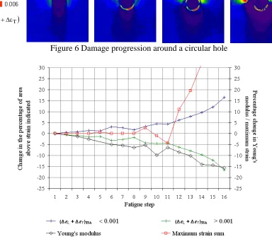
Figure 6 Damage progression around a circular hole
(ΔεL+ΔεT)
Figure 7 TSA strain metrics and Young’s modulus decrease during damaging fatigue
Figure 8 Progression of damage around a hole in a woven GRP specimen – TSA data from an impact load on a cantilever beam
Full scale assessments of sandwich structure: linking cost and performance
Figure 9 Linking cost of manufacture with performance
[image:7.612.150.475.411.657.2]Concurrent Engineering
Commonly, small FRP boat design and production in the leisure industry is inefficient by being sequential in practice and in a highly competitive market attention has been turned to alternative successful design and production techniques employed in other sectors. Improving the design process can have a significant impact on the cost of the final product – whilst around 5% of the final product cost comes from design costs, design value can affect the final product cost by up to 80%. In the aerospace and automotive industries, concurrent engineering uses parallel instead of sequential design processes, thereby allowing simultaneous changes necessitated by inputs from, for example, production engineers, quality assurance, structural engineers, outfitters and classification societies to lead to a rapid optimal design, reducing design and production times and increasing quality with little penalty in cost. The aim of current work is to assist the UK boat building industry to embrace modern integrated design and production techniques to help maintain and improve its competitive position and speed up new product introduction.
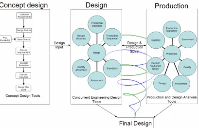
[image:8.612.111.520.362.625.2]The work undertaken to date [17-19] has concentrated on four main areas, namely materials database issues, design codes and standards, production process modelling and concurrent engineering principles. Using a web-based environment with easily accessible Microsoft Access™ and Excel™ facilities, concept design, detailed design and production can be fully integrated, as shown in Figure 11.
Figure 11 Diagrammatic representation of concurrent engineering environment for FRP boat design and production
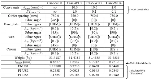
a genetic algorithm. Table 1 gives an example of optimised layup schedules for unidirectional stiffened panels under 4 different stiffness and strength criteria. Alternative panel limit states can be incorporated using relevant failure criteria for differing modes of loading: Table 2, for example, shows the influence of including the constraints of 4 failure models including buckling on the weight and cost of a stiffened panel in the boat’s sideshell (6m2).
To incorporate the importance of design histories in optimised design, the application of neural networks to facilitate self learning within the concurrent engineering environment is envisaged; thereby lessons can be learnt for new designs from records of previous design successes and failures, helping to make concurrent engineering philosophies and practice a step change in the UK small FRP boat production sector and an injection for international competitiveness.
Table 1 Weight minimisation of unidirectional stiffened FRP plate subject to stiffness and strength constraints (FI is failure index)
Calculated deflection
Calculated FI’s (3 locations)
Input constraints
Mass (kg) Cost (£)
Lloyds Register SSC Rules: 151.42 371.92
Analytical approach:
Strength limit state 88.11 338.56
[image:9.612.69.557.220.477.2]Strength, Deflection & Buckling limit states 104.12 315.60
Table 2 Effect of limit state constraints on stiffened FRP panel weight and cost
Life Cycle Assessment: thermoplastic matrix composites
alternative to thermoset composites for a number of years. The marine industry cannot use costly high-performance materials which require specialised curing cycles. Therefore there has been increasing interest in the use of cheaper and lower performance polypropylene thermoplastics and glass reinforcements as a recyclable and durable structural material. Current work is investigating the life cycle of a marine structure from raw material to full disposal using an embodied energy approach [20].
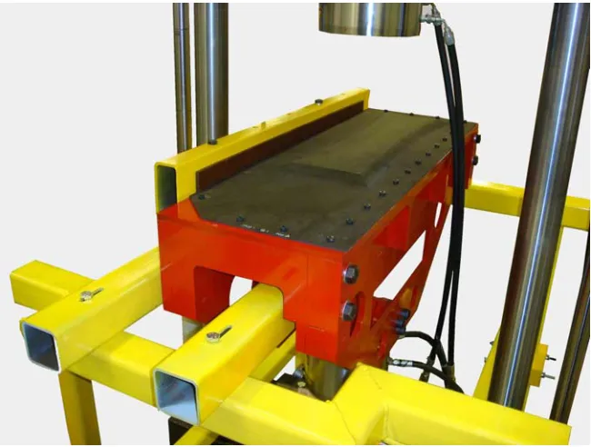
A grillage structure is used to highlight the issues concerned. Four materials were considered, steel, aluminium, glass reinforced epoxy (GRE) and TMC. Plate thickness and stiffener dimensions were determined in order to ensure that the stress in the grillage did not exceed 60% of the yield stress of the material and that the mid-point deflection of the panel did not exceed 1% of the panel width. The dimensioning was conducted using Vedeler’s analytical model for grillage structures. The initial results were presented as a weight value and showed that steel (107 kg) and aluminium (38 kg) were the heaviest options. Both GRE and TMC were lighter at 28 kg and 23 kg respectively. Data was collected regarding the energy required to manufacture the raw materials for all four material choices. Manufacturing methods were explored and the associated energy consumption calculated for cutting and joining. Post life disposal methods were examined, recycling as the option for both steel and aluminium and mechanical and incineration options explored for the composite materials. The results of the energy analysis are shown in Figure 12. Two results are provided for the energy required to produce the raw materials, the high value is for virgin material the low value is for material is obtained using recycling. The results show a large difference between virgin and recycled metallic materials, most possibly due to the process maturity of recycling metals. This is not reflected in the composite results. However, one cannot specify only recycled steel for construction and so the question remains - How much energy does steel manufacture consume? This will vary depending on the amount of recycled scrap is used in the process and the type of furnace that is used for steel manufacture. For the composite results there is little difference between virgin and recycled materials. In general recycling in this study was the generation of energy through incineration of the used composite which can offset the energy required to manufacture new material.
Figure 12 Results of embodied energy analysis for candidate materials
Conclusions
1. Enhanced levels of fundamental understanding of the load transfer mechanisms in layered orthotropic structures using empirical, physical means to ensure enhanced confidence in theoretical modelling capabilities.
2. Better appreciation of the modelling of safety concerns that account for potential variabilities and uncertainties in material and structural behaviour.
3. Life cycle assessment of composite structures, leading to cradle to grave design concepts, that are better able to account for environmental impact based on energy considerations.
4. Development of concurrent engineering approaches that account for design-production interaction leading to specification of optimal design choices from a costings viewpoint.
5. Identification of apt inspection, intervention and repair strategies for ensuring continued structural health of the artefact through its life.
Underpinning these key challenges for the future are two larger societal concerns. Firstly, on an economic front, we need to ensure that CAPEX and OPEX of ships, boats and other marine artefacts, are optimised and the materials specification leads to such a goal. Secondly, with ever growing concern for sustainability, it is important to appreciate and understand life cycle issues from an environmental impact viewpoint.
Acknowledgements
The authors are grateful to the following individuals and organisations for their financial support for this research and/or their collaboration:
• UK Engineering and Physical Sciences Research Council
• UK Arts and Humanities Research Council
• UK Technology Strategy Board
• Lloyds Register through our University Technology Partnership
• RNLI through our Advanced Technology Partnership
• DSTL/MOD, particularly Dr Alan Groves
• AWE, particularly Mr Paul Tatum
• Airbus UK, particularly Dr Richard Burguete
• BAE Systems, particularly Dr Peter Foote and Dr David Tunnicliffe
• QinetiQ through the MAST program
• GE Aviation, particularly Mr John Savage
• Fiberline AS
• British Marine Federation
• National Composites Network
• Aalborg University, particularly Professor Ole Thomsen and along with this Dr Yapa Rajapakse, Program Manager Solid Mechanics, US Office of Naval Research
References
[1] Dulieu-Barton J.M. and Stanley, P., “Development and applications of thermoelastic stress analysis”, Journal of Strain Analysis for Engineering Design, 1998, 33, 93-104.
[2] Sahin, M. and Shenoi, R.A., “Vibration-based damage identification in beam-like composite
[3] Sahin, M. and Shenoi, R.A “Quantification and localisation of damage in beam-like structures by using artificial neural networks with experimental validation”, Engineering Structures, 2003, 25, 1785-1802.
[4] Chetwynd, D., Mustapha, F., Worden, K., Rongong, J.A., Pierce, S.G and Dulieu-Barton, J.M., “Damage Localisation in a Stiffened Composite Panel”, Strain, 2008, 44, 298-307.
[5] Eksik, O. Shenoi, R.A., Blake, J.I.R. and Jeong, H.K., “Damage mechanisms in hat-shaped GRP beams”, Journal of Reinforced Plastics and Composites, 2004, 23, 1497-1514.
[6] Xiong, J.J. and Shenoi R.A. ‘A two-stage theory on fatigue damage and life prediction of composites’, Composites Science and Technology, 2004, 64, 1331-1343.
[7] Wang, W., Shenoi, R.A. and Cui, W. “Delamination buckling of a curved composite beam subjected to a closing bending moment”, Journal of Ship Mechanics, 2006, 10, 102-114.
[8] Eksik, O., Shenoi, R.A., Moy, S.S. J., and Jeong, H.K.: “Finite element analysis of top-hat stiffened panels of fibre reinforced plastic boat structures, Marine Technology, 2007, 44, 16-26.
[9] Boyd, S.W, Blake, J.I.R., Shenoi, R.A. and Kapadia, A. “Integrity of Hybrid Steel-to-Composite Joints for Marine Application”, Journal of Engineering for the Maritime Environment, Proceedings of the Institution of Mechanical Engineers, Part M, 2004, 218, pp235-246.
[10] Emery, T.R., Dulieu-Barton, J.M., Earl, J.S. and Cunningham, P.R., “A generalised approach to the calibration of orthotropic materials for thermoelastic stress analysis”, Composites Science and Technology, 2008, 68, 743-752.
[11] Pitarresi, G., Found, M.S. and Patterson, E.A., “An investigation of the influence of macroscopic heterogeneity on the thermoelastic response of fibre reinforced plastics”, Composites Science and Technology, 2005, 65, 269-280.
[12] Frühmann, R.K., Dulieu-Barton, J.M. and Quinn, S., “On the thermoelastic response of woven composite materials”, Journal of Strain Analysis for Engineering Design, 2008, 43, 435-450.
[13] Boyd, S.W., Dulieu-Barton, J.M., Thomsen, O.T. and Gherardi, A., “Development of a finite element model for analysis of pultruded structures using thermoelastic data”, Composites A, 2008, 39, 1311-1321.
[14] Johannes, M., Dulieu-Barton, J.M., Bozhevolnaya, E. and Thomsen, O.T., “Characterisation of local effects at core junctions in sandwich structures using thermoelastic stress analysis” Journal of Strain Analysis for Engineering Design, 2008, 43, 469-492.
[15] Crump, D.A., Dulieu-Barton, J.M. and Savage, J., “Manufacturing options for secondary aircraft CFRP sandwich components” Proceedings of 16th International Conference on Composite Materials, 2007, Kyoto, 8 pages on CD.
[16] Crump, D.A. and Dulieu-Barton, J.M., “Full-field strain analysis of aircraft sandwich structures”, Proceedings of SEM XI International Congress on Experimental and Applied Mechanics, 2008, Orlando, 8 pages on CD.
[17] Sobey, A.J. and Blake, J.I.R. and Shenoi, R.A., “Optimization of composite boat hull structures”, Proceedings of the 7th International Conference on Computer and Information Technology in the Maritime Industries (COMPIT), 2008, Liege.
[18] Sobey, A.J. and Blake, J.I.R. and Shenoi, R.A., “Comparative optimisation of first principles design methods with classification society rules for boat hull structures”, Ship Technology Research, 2008, 54, 502–515.
[19] Sobey, A.J. and Blake, J.I.R. and Shenoi, R.A., “Optimisation of composite boat hull structures as part of a concurrent engineering environment”, 2008, Proceedings of the 6th International Conference on High Performance Marine Vehicles (HIPER), 2008, Naples.