ASPIRE: Ontology Workspace and
Problem Editor
Antonija Mitrovic
Brent Martin
Pramuditha Suraweera
Konstantin Zakharov
Nancy Milik
Jay Holland
Technical Report TR-01/06, 28 February 2006
Intelligent Computer Tutoring Group
Content
1. Introduction...3
2. Ontologies in ASPIRE ...4
2.1. Ontology Development...5
2.2. Ontology Workspace ...6
3. Problem Editor...10
4. Updated Class Diagram...17
4.1. Domain Structure ...18
4.2. Domain Ontology...18
4.3. Problem Solution Structure...18
4.4. Problems and Solutions ...19
5. Conclusions...19
1. Introduction
This document reports the work done from 1.12.2005 to 28.2.2006 on the ASPIRE project, funded by the e-Learning Collaborative Development Fund grant 502. In this project, we are developing a Web-enabled authoring system called ASPIRE, for building intelligent learning agents for use in e-learning courses. ASPIRE will support the process of developing intelligent educational systems by automating the tasks involved, thus making it possible for tertiary teachers with little computer background to develop systems for their courses. The resulting educational systems will overcome the deficiencies of existing distance learning courses and support deep learning.
ASPIRE consists of ASPIRE-Author, the authoring server, and ASPIRE-Tutor, the tutoring server which delivers the resulting intelligent educational systems to students. In the first report on the ASPIRE project (Mitrovic et al., 2005a), we presented the background for the project, functional specifications and the overall architecture of ASPIRE. We also discussed the functionality of the system in terms of user stories, the knowledge representation language used for developing domain models, and finally presented the Session Manager, the first component of ASPIRE to be developed.
In the second report (Mitrovic et al., 2005b), we presented the implementation of the general framework necessary for authoring, the packages and classes structure for both ASPIRE-Author and ASPIRE-Tutor, and the completed components. On the authoring side, we discussed three components of the authoring interface: Domain Structure Modeller, Problem/Solution Structure Modeller, and the Student Interface Builder. The Domain Structure Modeller allows the author to specify the general characteristics of the chosen instructional domain. This information is stored as the initial part of the domain model. The author then specifies the structure of problems and solutions in the domain. The Student Interface Builder supports the author in specifying the initial version of the student interface, which will be used to communicate with students. We also discussed two components of ASPIRE-Tutor: Diagnostic Module, and Student Modeller. The Diagnostic Module analyses the solutions submitted by students, identifying any potential errors in them. The result of the analysis is the short-term model of the student, reflecting student's performance on the current problem. The Student Modeller, on the other hand, maintains the long-term model of the student's knowledge, reflecting the history of the student's performance during his/her interaction with the instructional system. Finally, we briefly presented AllegroStore, the underlying object-oriented database storing all the necessary data.
As discussed in the previous reports, the development of the domain model is the most complex and time-consuming task. ASPIRE supports this process by automating it. The authoring process in ASPIRE consists of the following seven steps:
1. Modelling the domain structure;
2. Composing an ontology of the domain;
3. Modelling the problem and solution structures;
4. Designing the student interface;
5. Adding problems and solutions;
6. Generating constraints (syntax and semantic);
7. Validating the generated constraints.
2. Ontologies in ASPIRE
An ontology describes the structure of the domain by showing the basic domain concepts, their properties and the relationships between concepts. A widely accepted definition is that an ontology is a specification of a formalisation (Gruber, 1993); in other words, it is an explicit, formal specification of the domain vocabulary which presents a common understanding of topics that can be communicated between users and applications. An ontology thus enables all the people involved to speak the same language, supporting knowledge sharing by applications and reuse. An ontology makes domain assumptions explicit, so that it is easier to change the domain description, as well as to understand and update existing data. An important feature of ontologies is that they separate domain knowledge from operational knowledge, in the same way in which a database schema is separated from the actual data stored in a database.
Initially, ontologies have been introduced within the field of Artificial Intelligence, but are now becoming widely used on the World Wide Web, as the foundation for the Semantic Web. In contrast to a large number of documents linked together, a Semantic Web is a huge network of machine-understandable and machine-processable human knowledge (Decker et al., 2000; Hendler, 2001, 2005). The WWW Consortium (W3C) has proposed several languages1 for encoding knowledge on the Web so that it can be used by intelligent agents to improve their performance. Key application areas of ontologies include e-commerce and search engines, among others.
Ontologies play a crucial role in ASPIRE. As the goal of ASPIRE is to make the authoring process easy for non-computer specialist teachers, we proposed an authoring process which relies on the domain ontology. Instead of asking the domain author (i.e. the teacher) to manually encode domain knowledge using a specific knowledge representation language, authoring in ASPIRE requires the author to specify the domain ontology. This is a much simpler requirement, as the authors do not have to learn the knowledge representation language and the specifics of a particular approach to using domain models. Authors are already aware of domain ontologies, even though they might have a simplified (i.e. informal) representation. In addition to specifying the domain ontology, the author enters examples of problems and their solutions. All three sources of knowledge (ontology, problems and solutions) are then analysed, and the domain model comprising the set of constraints is induced.
The authoring process was discussed in (Mitrovic, et al. 2005a). In the first phase, the author specifies the general characteristics of the chosen instructional domain, such as its name, description and type (procedural or declarative). To do this, the author uses the Domain Structure Modeller. For procedural domains, the author also specified the steps involved in solving problems. The ontology composition stage is the second phase of the authoring process. During this stage, the author develops the domain ontology using the Ontology Workspace, which is one of the components of ASPIRE-Author (Figure 1).
1
Web Interface
Ontology
Workspace
Authoring Interface
Validation/
Constraint
Authoring Controller
Domain Model
Manager
Domain model
Constraint Generator
Syntax Semantic
Constraint
validator
Problem/
Solution
Editor
Student
Interface
Designer
Problem Solution
Structure Modeller
Domain
Structure
Modeller
Figure 1. The architecture of ASPIRE-Author
In Section 2.1, we discuss the process of ontology development in general. Section 2.2 then discusses the Ontology Workspace, the component which supports the author while specifying the ontology. The following subsections describe the steps in developing an ontology, and illustrate how they are performed in the Ontology Workspace.
2.1. Ontology Development
There is no silver bullet when it comes to ontology development; similar to other design tasks, ontology development is under-specified and ambiguous. Therefore, there is neither one correct approach to ontology development, nor a single best ontology for a particular domain (Noy and McGuinness, 2001). In order to specify a domain ontology, the author needs to specify domain concepts, their properties and relationships between concepts. Each ontology will reflect the author’s subjective view of the domain, and of the importance of domain concepts. The process is always iterative. Initially, it is necessary to decide on the scope of the ontology - how much of the domain will it cover? Generally, it is possible to reuse existing ontologies available on the Web, although there are a few ontologies available for educational domains that are directly applicable. In ASPIRE, we assume that authors will develop their own ontologies from scratch.
There are many ontology-development tools available, most popular of which are Protege2, Ontolingua3 and OilEd4 . These tools support different ontology languages and vary in terms of their expressiveness, reasoning abilities and support for users.
2.2. Ontology Workspace
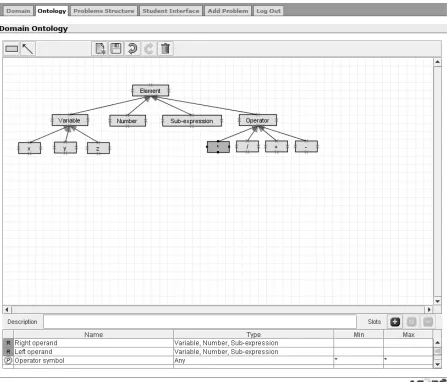
In ASPIRE, ontologies are represented in terms of a taxonomy, in which concepts are related via the 'is-a' relationship. The Ontology Workspace, as shown in Figure 2, is a graphical ontology-development tool, which supports a rich knowledge model. The taxonomy is represented as a set of concepts (rectangular boxes) connected with arrows, representing the 'is-a' relationship.
[image:6.595.81.528.279.661.2]We will illustrate the process of ontology development on the example of the fraction addition domain. After logging in, the author needs to specify the domain to work with. When the “Ontology” tab is chosen, the Ontology Workspace is presented to the user for composing an ontology of the domain.
Figure 2. Interface of ontology workspace
2
http://protege.stanford.edu/ 3
http://www.ksl.stanford.edu/software/ontolingua/ 4
Typically, each ontology has a concept that represents the most general concept in the taxonomy. Each concept may have a number of subclasses that represent more specific concepts. For example, Figure 2 shows an ontology for adding fractions. It has Element as the most general concept and
Variable, Number, Operator and Sub-expression as its subclasses. Variable is further specialised
into X, Y and Z, whereas Operator is specialised into the three arithmetic operators, *, /, + and -.
In order to develop an ontology, the author needs to specify the domain concepts of interest, how they are arranged into a hierarchy (subclass-superclass), the properties of concepts and additional relationships between concepts. Some ontologies also contain instances (i.e. classes) of concepts. The Ontology Workspace does not support the definition of instances directly; however, instances are entered in the later phases of the authoring process. For example, as in Figure 2, the author may specify ‘Number’ as a concept during the ontology development phase. Later on, while specifying examples of problems and solutions, the author enters the problem ‘Solve x for: 2x =
10’ and its solution as the number ‘5’; this solution is an instance of the ‘Number’ concept.
Once the domain expert completes the process of developing an ontology, he/she can click on the save button to persist the ontology. The applet also automatically saves the final state of the ontology when the user selects another interface module by clicking on an active tab on the top of the interface. When the applet receives a save request, it produces an XML representation of the composed ontology and sends it to the server. The server converts the received XML representation of the ontology in to an object representation. The structure of classes used for representing an ontology is discussed further in Section 4.2.
2.2.1. Defining concepts
Defining concepts using the Ontology Workspace is similar to using a drawing tool. The user has to click on the concept button (the rectangle tool in the tool bar shown at the top of the drawing area in Figure 2) and indicate the rectangular region to be occupied by the concept by dragging the mouse. The concept can be named by double clicking on the drawn rectangle.
The super/subclass relationships are represented graphically using arrows, referred to in this report as connectors. The direction of the arrow indicates the superclass. After clicking the connector button, users can draw the connector by dragging the mouse pointer. The Ontology Workspace assists in connecting concepts with connectors by automatically connecting endpoints of a connector with a concept handle within a range of 5 pixels.
2.2.2. Defining properties of concepts
When the author selects a concept from the taxonomy, its details are shown in the bottom section of the Ontology Workspace. For example, Figure 2 shows a situation when the currently select concept is * (the multiplication operator), and the details of this concept are shown below the taxonomy. The details panel includes a text area for adding the description of the concept and a table that lists the concept's slots. This concept consists of three slots: Left operand, Right operand and Operator symbol. The Left operand and Right operand slots are inherited from its super concept Operator.
Slots can be either properties of a concept that describe that concept, or relationships with other concepts in the ontology. Both properties and relationships are added by clicking on the “+” button in the details panel, which opens up a form-based interface. The "-" button deletes the currently selected slot from the table, while the “M” button brings up the slot definition form, so that the author can modify it. The icon in the first column indicates whether the slot is a property or a relationship. Properties are identified by P and relationships by R. In Figure 2, the Operator
type of the slot in the case of properties. On the other hand, if the slot is a relationship, the related concepts are displayed.
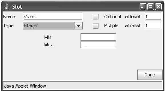
The slot definition frame is illustrated in Figure 3. It is designed to extract all slot-related information from the author. The slot must have a unique name, and its type must be specified. The slot's type dictates whether it is a property or a relationship. A property may have values of type Boolean, integer, string, float, or symbol. However, the type of a property does not have to be specified, as is the case with the Operator symbol property in Figure 2. If a slot represents a relationship between the current concept with another concept in the ontology, its type must be set to relationship (see Section 2.2.3).
The Optional checkbox allows the author to specify whether the slot is optional or mandatory. An optional property means that not all objects of this type will have a value for that property. The cardinality restriction of the slot is specified using the Multiple checkbox; if this box is checked, the slot can have multiple values. In the opposite case, there can be only one value of that slot for an instance of the concept. If the slot allows multiple values, the author can specify the minimum and maximum number of values precisely by using the at least and at most text boxes. Minimum cardinality of n means that a slot must have at least n values.
[image:8.595.153.442.405.564.2]The bottom part of the slot input frame depends on the type of slot. For numerical properties (integer or float) and strings, it displays input boxes for specifying the range of the property. Figure 3 shows the slot definition form, in which the author is defining the Value property, which must have a single integer as its value. The “Optional” box is not ticked, meaning that the value of this property is mandatory. The author can specify the minimal and maximal allowed value for that property.
Figure 3. Specifying a property of type integer
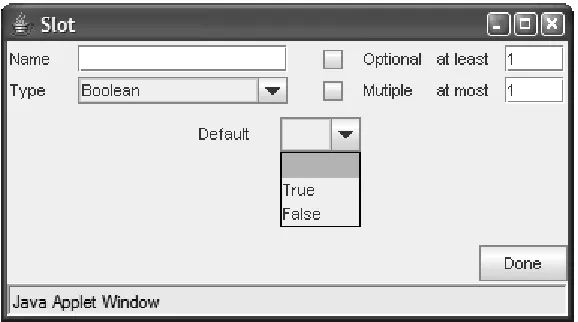
Figure 4. Specifying a Boolean property
[image:9.595.152.441.322.482.2]If the property is of type symbol, the author needs to enumerate the allowed values (Figure 5), by entering them one at a time and clicking the “+” button. To delete a previously specified value, the author needs to select it and click the “-” button.
Figure 5. Specifying a property of type symbol
2.2.3. Defining relationships
To specify a relationship between the currently selected concept and another concept from the ontology, the author clicks the “+” button in the Details frame, which brings up the slot definition frame. After specifying the name of the slot, the author needs to select “relationship” as its type. Figure 6 shows the input frame for specifying a relationship named Left operand for the Operator concept. In order to specify the related concept, the author needs to select an option from the drop-down list of concepts, which lists all the concepts from the current ontology.
Figure 6. Relationship slot input frame
3. Problem Editor
The Problem Editor allows the author to specify problems for students to solve. ASPIRE-Tutor will later deliver these problems to students via the student interface.
In the previous report (Mitrovic et al., 2005b), we have presented the component for specifying the structure of problems and solutions (labelled Problem/Solution Structure Modeller in Figure 1). Once the author specifies the structure of problems and solutions in phase 3 of the authoring process, these structures are stored within the domain model. In phase 4, the author specifies the student interface to be used to communicate with students. The interface specification is also a part of the domain model. In phase 5, the author enters problems to be given to students, and also a set of solutions for each problem. This phase is supported by the Problem Editor.
[image:10.595.94.497.516.672.2]The interface for entering problems and solutions is similar to what the student will see when they interact with the educational system. To generate this interface, ASPIRE-Author uses the previously specified problem/solution structures. Therefore, when the author starts adding the first problem for the domain, the Problem Editor provides the author with the necessary interface widgets, based on the problem structure, and expects the author to populate them.
Figure 7. The initial state of the Problem Editor
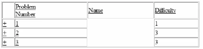
opens a new window showing the desired information (shown in Figure 8). The new window shows all the problems entered along with their general attributes. The author is able to view the full problem text by clicking on the “+” sign. Clicking on the problem number will display the problem in the main window along with the options to edit or delete the selected problem. The author is also able to decide on the default order of problems5 to be presented to students by sorting the problems by their specified attributes.
Figure 8. View all problem pop-up window
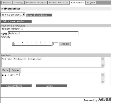
Figure 9 shows the screenshot of the Problem Editor when the author asked for a new problem to be added. There are several general problem features to specify, shown in the “Problem’s
attributes” area. The unique problem number is generated automatically by the system. The author
may specify a name for the problem, which is optional. If the problem name is specified, it will be shown to students together with the problem number; otherwise, students will only see the problem number. The author must specify the problem difficulty, which ranges from 1 to 9. To specify the difficulty level, the author can use the slider, or enter the desired number into the text box. If the text box is used to enter the difficulty number, the author needs to click the “Update” button for the difficulty to be updated on the slider shown.
Next, the author needs to specify the task the student is to perform. As discussed in Section 2.4.1 of the previous report (Mitrovic et al., 2005b), in some subdomains all problems will have the same general description of what the task is: e.g., in a language tutor, this description might be:
“Turn the following verb into a noun,” and the student is given a series of verbs to work on. On
the other hand, in certain domains/subdomains, there is no such general description, and every problem will have distinct instructions. The author specifies whether there is such a general description for the subdomain as well as any additional components for the problems (e.g. a diagram) in phase 3, and this information is available within the domain model.
5
The presentation of problems to students in ASPIRE-Tutor will depend on the problem selection algorithm
Figure 9. Adding a new problem
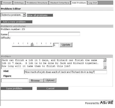
If the general description of the problem exists, it will be the same for all the problems in the current subdomain. Figure 8 shows the author adding a problem for the fraction addition domain; in this case, there is a general description for all problems, so the author only needs to specify the problem statement. When entering the additional problems for the same subdomain, the previously specified general problem instructions will appear automatically, as shown in Figure 9, where the general statement is “Add the following fractions:”. In order to update these instructions, the author would need to click the Edit general statement button (note that modifying this general problem instruction for a specific problem effectively changes it for the whole subdomain). Figure 10 shows the state of the Problem Editor when the author is adding a new problem for a subdomain without a general problem instruction.
Figure 10. Adding a new problem with components
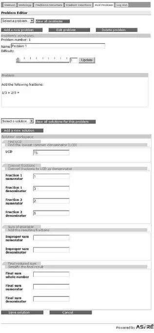
Figure 11. The state of the Problem Editor after saving or viewing a problem
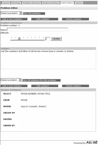
Once the author is satisfied with the solution, it can be saved by clicking on the “Save solution” button. The saved solution is then displayed, as illustrated in Figure 13. In this particular case, the author has added a solution for an SQL problem, which is a non-procedural domain.
The author may choose to enter problems first and then add their solutions at a later time. The Problem Editor differentiates between fully completed problems with their solutions, problems without solutions and partially entered problems by highlighting the name of the problems in both the drop down menu and the pop-up window. The partially entered solutions are also highlighted in a similar manner.
[image:16.595.127.469.250.747.2]As shown in Figures 11 and 13, the author is also able to edit or delete any solution or problem previously entered by clicking on the Edit or Delete buttons respectively. Deleting a problem, however, will also delete all of its solutions at the same time.
4. Updated Class Diagram
Figure 4 in the previous report (Mitrovic et al., 2005b) illustrated the domain model classes at the end of the previous reporting period. We have extended the domain model with classes necessary to represent domain ontologies (produced using the Ontology Workspace), and problems and their solutions (produced using the Problem Editor). Figure 14 illustrates the extended UML diagram, depicting all classes related to the four main components of the domain model: domain structure, domain ontology, problem/solution structures, problems and solutions. All classes in this diagram are shared between ASPIRE-Author and ASPIRE-Tutor.
Problems and solutions Problem solution structure Domain structure Domain ontology -id -name -description -is-procedural domain-model -nameontology 1 1 -id -name -description -page-number problem-solving-step 1 * -name -description -scaffolding -has-fixed-problem sub-domain 1 * -label -type problem-component-structure 1 * -step-idsolution-structure 1 * 1 * -id -label -type -elements-count -rows -length solution-component-structure 1 * -id -name -description -x -y -width -height concept 1 * 1 * -id -p1-x -p1-y -p2-x -p2-y -p1-concept-id -p2-concept-id generalise-connector -name -type -min-cardinality -max-cardinality -min-value -max-value -symbols-list property -name -type -min-cardinality -max-cardinality -related-concepts relationship 1 * 1 * 1 * * 1 1 2 -id -name -statement -difficulty -order-index -components Problem
-idSolution -id-components
Step-Solution
1 * 1 *
1
*
Domain models are maintained by the Domain Manager. Users of ASPIRE-Author modify domain models using the provided interface modules, such as the Domain Structure Modeller, Ontology Workspace etc. The domain model components composed using the authoring interface are transferred to the Domain Manager for persistence as XML representations. The XML representations received by the Domain Manger are parsed to produce the corresponding object structure. The domain manager is also responsible for producing an XML representation of the domain model components when requested by the interface.
4.1. Domain Structure
As discussed in the previous report (Mitrovic et al., 2005b), the structure of the domain is represented using the domain-model, sub-domain and problem-solving-step classes. The
domain-model class holds general details of the domain such as its name, description and whether it is procedural or not. A domain consists of sub-domains, which are recorded in the sub-domain class. Each sub-domain is described by its name, description and scaffolding information. Procedural domains would have a number of problem-solving-step objects that describe the steps to be carried out to solve problems in the domain. On the other hand, each non-procedural domain has a single default problem-solving-step object attached to the domain-model.
4.2. Domain Ontology
A domain ontology, identified by its name, consists of a collection of concepts and generalisation connectors. Both concepts and connectors contain positional and dimensional data for reproducing the graphical ontology diagram produced by domain expert. As concepts are represented as rectangles in the ontology diagram, the concept class has attributes for the x and y coordinates of the top left point of the concept rectangle. It also contains attributes for the width and height of the rectangle. The generalise-connector class keeps track of the positions of both end points of the connector (p1-x, p1-y etc). The generalise-connector also records the ids of the concepts attached to each of its end points.
A concept contains properties and relationships represented by the property and relationship
classes respectively. Both properties and relationships are described by their name, type and minimum and maximum cardinalities. A property also has attributes to record its range in terms of a minimum and a maximum. A property of type symbol has a list of distinct values that it may hold, which are recorded in the symbols-list of property. Since relationships occur between concepts, the relationship class also keeps track of the concepts involved in the relationship.
4.3. Problem Solution Structure
Each sub-domain has its own structure for problems and their solutions. A problem can consist of a collection of problem components that can be either textual (such as a statement describing a scenario) or graphical (such as a diagram that illustrates the scenario). The problem component details are represented by the problem-component-structure class.
The composition of a solution to problems offered to students is stored as a solution-structure object. Procedural domains would have a set of solution-structure objects equal to the number of steps involved in solving a problem. On the other hand, non-procedural domains would only have a single solution-structure object. The structure of a solution or a problem-solving step is represented as a collection of solution-component-structure objects. A
4.4. Problems and Solutions
Problems and solutions are composed according to the problem/solution structure specified during the third step of the authoring process. The Problem Editor produces a form-based interface for composing problems and their solutions based on the problem and solution structure.
Problems created by the author (i.e. domain expert) are stored as a list within the relevant sub-domain. The problem class records all the problem related information such as its name, problem statement, difficulty etc. The author is free to arrange the problems in a specific order, in which they will be presented to students. This ordering of the problems is recorded in the order-index
attribute of the problem class.
Domain experts are encouraged to enter a set of solutions for each problem, depicting different ways of solving the problem. Each new solution results in a solution object. Students working on problems in a non-procedural domain only have to submit a single solution, whereas problems in procedural domains require a solution for each step. As a result, solutions for problems in procedural domains consist of a collection of step-solution objects, one for each step. Solutions for problems in non-procedural domains consist of a single step-solution object. The step-solution class records all the components of the solution in a list according to the same order as the solution-component-structure objects within the solution-structure.
5. Conclusions
This report covers the third reporting period of the ASPIRE project, and presents the progress made on ASPIRE-Author. We have implemented two new components on the authoring side: Ontology Workspace and Problem Editor. The Ontology Workspace supports the author in specifying the domain ontology (step 2 of the authoring process), while Problem Editor allows the author to specify problems to be given to students, and to specify a set of solutions for each problem (step 5).
6. References
1. Decker, S., Melnik, S., van Harmelen, F., Fensel, D., Klein, M., Broekstra, J., Erdmann, M., Horrocks, I. (2000) The Semantic Web: The Roles of XML and RDF. IEEE Internet Computing, 4(5), 63-74.
2. Gruber, T.R. (1993) A Translation Approach to Portable Ontology Specification. Knowledge Acquisition, 5, 199-200.
3. Hendler, J. (2001) Agents and the Semantic Web. IEEE Intelligent Systems, 16(2), 30-37. 4. Hendler, J. (2005) Knowledge is Power: a View from the Semantic Web. AI Magazine,
26(4), winter 2005, 76-84.
5. Mitrovic, A., Martin, B., Suraweera, P., Zakharov, K., Milik, N., Holland, J. (2005a) ASPIRE: Functional Specification and Architectural Design. Tech. Report TR-COSC 05/05, University of Canterbury.
6. Mitrovic, A., Martin, B., Suraweera, P., Zakharov, K., Milik, N., Holland, J. (2005b) ASPIRE: Student Modelling and Domain Specification. Tech. Report TR-COSC 08/05, University of Canterbury.