The Influence of Earthquakes on Open-Pit Slope Stability
Sergei Vadimovich Tsirel, Boris Yurievich Zuev, Anton Anatolevich Pavlovich State Mining University, St. Petersburg, Russia
Email: [email protected], [email protected], [email protected]
Received July 26, 2012; revised August 28, 2012; accepted September 6, 2012
ABSTRACT
Estimation of stability of natural slopes, embankments, dams and open-pit slopes during earthquakes are complex and non-linear problems, therefore physical modeling is used for decision of it. As a result of physical modeling the pattern of seismic vibrations impact based on the movement process of probable collapse prism delineated by the most stressed plane of sliding has been established. Particular recommendations on the basis of safety factors selection in seismoac-tive zones are given.
Keywords: Earthquakes; Open-Pit Slope Stability; Safety Factor; Pseudostatic Approach
1. Introduction
At present, the explored reserves of a whole number of mineral resources are being exhausted at the readily ac-cessible shallow deposits in safe seismic regions in Rus-sia. Therefore, construction of new deep open pits and deepening of existing ones under complicated geologi-cal-and-mining, including seismic-dangerous, conditions is a high-priority task in Zabaykalie, Tyva, the Far East, Sakhalin, etc. In addition, at many mining regions with enormous amounts of excavated materials (e.g. Kuzbass, the Kola Peninsular, many zones of the Urals) one can observe the growth of technogeneous seismicity, that leads to enhance the influence of seismic waves on open-pit slope stability. Figure 1 shows the basic coal
open-pits located within the zone of seismoactive zones of Russia. At present, most of them are positioned at Kuzbass within the zones of vibration level VI-VII, but, however, as exploring for mineral resources in Siberia and the Far East, it is expected the rise of number of opencasts being located within the zones of the intensity VIII and even IX of seismic vibrations.
The most widespread method of seismic impact ac-counting on stability of open pit edges and open pit slopes is pseudo static approach [2-10]. However appli-cation of it leads to sufficient strong overstating of safety factor and ignores existing information about influence of relative small but longstanding oscillations from far earthquakes on the slopes stability, for instance [11].
Alternative method of accounting of earthquake vibra-tion influence involves transfer of evaluavibra-tion methods of seismic-explosive waves influence on the influence of seismic waves [12-15]. At that it is suggested to enter additional coefficients for accounting essential major
endurance and predominate period and all oscillation process [15].
In the foreign practice beside of pseudo static ap-proach [16-19], numerical dynamic calculations are used for evaluation of stability of natural slopes, embankments, dams and open pit edges at earthquakes by using different software packages (Abacus, Plaxis, ANSYS, Slope/W, Flack, UDEC, 3DEC) and Newmark’s deformational method [20-27].
For the numerical dynamic calculations are necessary detailed knowledge of structure and properties of slope including dynamic characteristics describing the wave’s propagation and dynamic strength, and also rheological properties reflecting the behavior of failing rock mass after short-term local excesses of dynamic ultimate strength. Actually, that makes rather problematic the real estima-tion of influence of earthquakes on open-pit slopes with the use of numerical methods.
strength and deformation characteristics and static ones, etc.
2. Methodology of Experiments
In this connection a decision was made to use the method of physical modeling. The problem in physical modeling was in that the effects of strong seismic waves on open- pit slope represent a simultaneous follow of slow (qua-sistatic) and dynamic processes, and each of them is of important significance. Therefore, in modeling with use of equivalent materials it was necessary to provide the similarity both of those and other processes.
Traditionally in physical modeling of open-pit slopes great models from rather weak and plastic equivalent materials were used, which may be deformed under their own weight [31]. This method, however, for modeling of seismic effects on open-pit slopes is not suitable due to a number of reasons: the use of mechanical ties highly af-fects the wave’s propagation; difficulty in creation of uniform dynamic load in the model of great dimensions; limitation of amount of tests preventing the statistical reliability of the results. In investigation of dynamic processes one can not ignore the wavy phenomena. Therefore, in modeling, first of all, it is necessary to en-sure the similarity of deformation characteristics of rock mass.
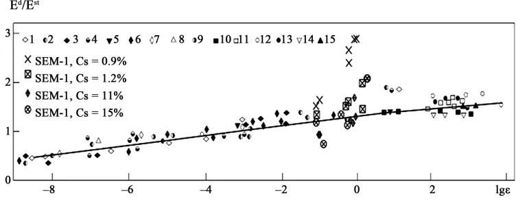
[image:2.595.59.536.414.720.2]Investigations of deformation characteristics of equiva- lent materials under dynamic and static loading condi-tions were carried out on models from sand-epoxyalipha- tic materials (SEM) with various percentage of bonding: 0.9%, 1.2%, 11% and 15%. With using standard methods the speed of elastic longitudinal and lateral waves was determined, as well as dynamic and static module of ela- sticity, strength in uniaxial compression. Tests have shown that in direct ultrasonic measurements of specimens from equivalent materials one observed high velocity of wave propagation, and difference between the dynamic and static module of elasticity amounted to 6 - 8 and even more times, i.e. there is a serious divergence of dynamic behavior in model equivalent materials and rocks. The nature of this divergence is in that during sonic tests of specimens the wave is registered which propagates basi- cally through hard grains to define more exactly the be- havior pattern of specimens from equivalent materials under strong dynamic impacts special measurements of deformation characteristics were carried out with the use of shock loading of various force and time-duration, and also the measurements with using the specially de- veloped strain gauges of deformations and stresses in specimens. Readings records of strain gauges were made with the use of Kreit LTR-EU-16-1 with tensometric moduli of LTR-212 mark.
The m o
ationship of examined phenomena in selected m
estab-data of modeling (M1: 500) of conditions are sh
3. Results of Experiments
s. The aim of the
he first step of modeling the influence of loading sp
ost important result of these tests was the fol- the slow and fast loading. Thus, the analogy was l wing: just under strong shock impact the dynamic
elas-tic characteriselas-tics and also the wave velocities are sub-stantially less than in ultrasonic test, and basically they differ from static ones approximately in those relation-ships as in the modelled rocks. The essence of difference is that heavy dynamic loading incorporates a slow proc-ess of pore comprproc-ession (or air bubbles in three-phase medium) retarding the wave propagation [32]. The higher loading speed, the more deformation processes affect immediately the rock mass (hard skeleton). The less load-ing speed, the more deformation occurs at the cost of long-term processes of compression of fractures, gas in bubbles, pores and joints, repacking of particles, etc. In-tensity of loading, naturally, affects in opposite direction,
i.e. high stresses will accelerate inclusion of slow proc-esses that increases their speed, however, these speeds remain much less than speeds of deformation of hard skeleton.
The rel
aterials provides closeness of the relation of their dy-namic and static deformation characteristics to the rela-tions of static and dynamic module of rocks (Figure 2)
and possible modeling of complicated processes merging
[image:3.595.109.485.385.532.2]lished between the behavior of rocks and equivalent ma-terials under dynamic loads (being a particular case of similarity in behavior of fractured and porous media [34,35].
Initial
own in Table 1.
Modeling was carried out by two step
first step was identify the qualitative estimation of the influence pulse duration on displacement sliding triangle. The second step—a quantitative estimation of the influ-ence of seismic effect duration on the slope stability with the development of the subsequent specific recommenda-tions.
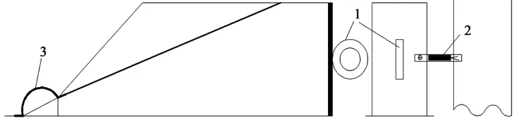
At t
eed on movement under dynamic impact was studied. The estimation of influence of pulsed loading duration was made on models with circular cylinder sliding plane (Figure 3) by delivering single blows with hammers of
various stiffness on strain gauge ring 1, “calibrated on loading”.
Figure 2. Comparison of relationships of elasticity module depending on speed of deformation compression for rocks [33] and
Characteristics Full-scale acc with ty
[image:3.595.309.537.582.707.2]equivalent materials: 1, 14—limestone; 2, 11, 12—sandstone; 3, 13—gabbro; 4—granite; 5—concrete; 6—marble; 7—tuff; 8—siltstone; 9—andesite; 10—anthracite; 15—argillite.
Table 1. Initial full-scale data for modeling.
On SEM ount of similari
Deformation properties of the model
Modulus of defor 50
al wave, m/s
mation, MPa 39.2 × 10³
Poisson’s coefficient 0.26 0.26
Velocity of longitudin 4400 200
Velocity of lateral wave, m/s 2500 115
Properties along contact
[image:3.595.56.289.597.736.2]Displacements of collapse prism were recorded with photographic camera. By the results of data treatment, obtained with using the photo- and tensiometric meas-urements, the relationship was obtained of displacements from frequency and blows force (frequency of vibrations induced by blowing effects, with account of similarity conformed to frequencies of seismoexplosive waves). The pulse duration for steel hammer was 0.7 ms, for hard rub-ber one –1.8 ms and soft rubrub-ber one –3.7 ms (Figure 4).
As is seen in Figure 4, the vibrations induced by the
forces of equal value with greater duration of pulses
deigns its movement only after over-co
on
wi
he time threshold after which the co
, cause more heavy displacements than with shorter pulses. The collapse prism
ming the certain threshold value of internal forces, depending on duration of pulses. Differences between pulses of various duration quantitatively analogous to differences of vibrations in blasting operations and earth- quakes. Acceleration in earthquakes is significantly less than in explosions, but most catastrophic aftereffects are observed just during earthquakes. One of basic reasons of this phenomenon is just different period of vibrations.
For estimation of influence of seismic effect duration the open-pit slope tests were carried out on models with sliding plane in the form of flat inclined contact (Figure 5), as base, the model was chosen with
inclina-tion angle 20˚ of sliding plane and calculated safety fac-tor 1.26. Measuring technique was analogous to the tests
th individual blows on model with circular cylindrical sliding plane. Modeling of seismic vibrations was made with the use of dynamic impact of cams with various values of eccentricity mounted on the engine shaft with alternating frequency of rotation allowing to reproduce various values of acceleration similar to the intensity range of vibrations in nature. Displacements of collapse prism were recorded with strain gauge in the form of cramp (further cramp-strain gauge), and accelerations induced by blowing impact (with cams) were determined with accelerometers and/or double differentiation of sig-nal of displacement gauge fixed at the glued to model end plane. With changes in rotation frequency and ec-centricity value the actual range of accelerations con-formed to intensities of seismic vibrations within the range III - VIII.
Practically in all tests the movement began with some retardation after start of vibrations, i.e. “mass” should have time for activation (t2) of mass, in which vibrations
cover the whole block and resistance to displacement is overcome induced by irregularity (of fractal structure) of potential slip surface. T
llapse prism sliding down begins, is expressed rather plainly (Figure 6). Respectively, irreversible
deforma-tions of slope may begin only after time t2 if the vibratory
[image:4.595.120.481.421.599.2]process terminates earlier, then the earthquake will not induce major irreversible deformations.
Figure 4. Relationship between displacement of collapse prism and the applied value of shock effects of various duration.
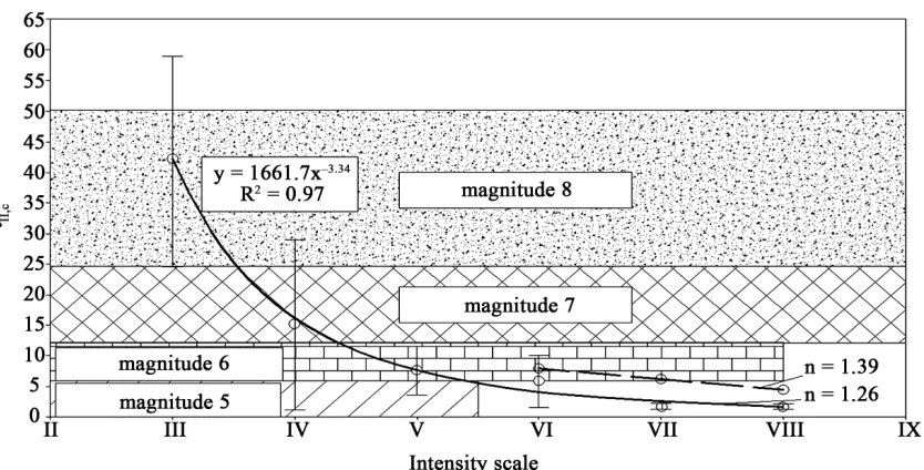
[image:4.595.111.486.634.725.2]In analysis of test results the relationship was revealed between the time of preparation t2 and intensity of
vibra-tions (Figure 7, all calculations are made for full-scale
values obtained by reverse recalculation with using the transient coefficients of modeling):
2
b
[image:5.595.87.527.118.473.2]t аI (1)
Figure 6. Records of strain gauges during block movement in various time scales.
prism and intensity of Figure 7. Graph of relationships between time necessary for preparation of sliding-down of collapse
[image:5.595.92.509.494.706.2]where a and b are empirical coefficients reflecting the contact conditions between blocks.
For slope with inclination angle 20 degrees of weakening plane and initial factor of slope stability n = 1.26 the co-efficients have the following values: а = 1660 and b = –3.34. Points at this graph represent the mean values of preparation time for each value of intensity of vibrations, nibs represent variations with reliability 95%. As is seen in the figure, the values of t2 have a significant spread
typical for seismic phenomena.
According to formula [36,37] total duration of vibra-tions during earthquake depends on its magnitude:
0.31 0.774
10 M
(2)
Respectively, with account of formulas (1) and (2) the irreversible deformations will occur, if duration of vibra-tions exceeds the time of preparation t2. More precise
presentation on emergence of irreversible deformations
y are presented in Table 2.
ions of the same in-te
sm was practically con-st
ement with each vibration consists of more i
forth and less intensive movemen ex
is connected w
1
t
the probabilistic estimations will give—for our base case
n = 1.26) the (
Thus, as is seen in this Table, magnitude of an earth-quake is of great importance. Vibrat
nsity have various influences on slopes, even weak vibrations of level III-IV from remote earthquake of magnitude 7 - 8 with a very high probability will lead to emergence of irreversible deformations.
As in tests vibrations had a quasiharmonic character and nearly constant amplitude, then according to de-scribed above Newmark’s approach the orbital velocity of displacement of collapse pri
ant (Figure 5). However, pay attention to the fact that
in more detailed examination it is seen that mov ntensive movement t back. Thus, in the periment no that variant of Newmark’s approach is being observed which was realized in basic programs, but another variant—of two-side movement or, more exactly, some intermediate one between them, but just more close to the two-side movement. In our opinion, realization of just such variant first of all
ith the presence of forces “elastic output”, developing in movement down, which indeed is not pure through sliding, but some combination of through sliding and deformation of surface sliding. In such case the condition of movement upwards is the following:
1 2 3 4
F F F F (3) where F1—seismic waves; F2—static holding forces;
F3—static moving forces; F4—forces of elastic output.
Close analysis of all tests has shown that with various periods of vibrations and different relationships of these forces the movement may have a reciprocating, intermit-tent or nearly continuous character.
However, the presence itself of irreversible
deforma-tions does not yet represent an immediate threat for slope stability, as indicated the investigations of the Institute VNIMI [31,38] irreversible deformations represent dan-ger for slope beginning only with certain values
According to formulas (1) and (2), a mean value of ir-reversible deformations will be:
100.31М 0.774 1661.7 3.34
s V I (4) where V is mean velocity of displacement.
The obtained mean velocities of displacements are presented in Table 3, relation V 0.26I5.2 was used for
their approximation. As is seen in the given formula and data in Table 3, with intensity of vibrations less V a
sharp decrease of displacement orbital velocity are ob-served, therefore it is sufficiently evident that vibrations of level III-IV cannot induce threatening irreversible de-formations of slope.
For more precise estimation of danger of obtained
reversible deformations of slope were used. Based on the values of displacements the data [31,38] on value of
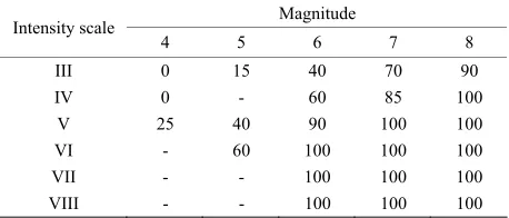
[image:6.595.309.538.403.501.2]ir-analysis of this data, the following typification was set up of probable aftereffects of deformations caused by dy-namic impact of seismic waves (Table 4).
Table 2. Probability of emergence of irreversible deforma-tions, %.
Magnitude Intensity scale
4 5 6 7 8
III 0 15 40 70 90
IV 0 - 60 85 100
V 25 40 90 100 100
VI - 60 100 100 100
VII - - 100 100 100
[image:6.595.307.537.528.628.2]VIII - - 100 100 100
Table 3. Mean velocities of vibrations.
Intensity scale Mean velocities, V, см/с
[image:6.595.308.539.666.737.2]III 1 IV 1.6 V 21 VI 30 VII 93 VIII 100
Table 4. Typification of probable aftereffects with various values of relative deformations.
Probable aftereffects Relative deformation
Potential formation of landslide >0.005 Irreversible deformations 0.001 - 0.005 Small irreversible deformations <0.001
Based on the suggested typification, consider, what aftereffects will emerge in the slope at different distances from epicentre of earthquake. For this purpose we shall use the common equation of microseismic field of crustal earthquakes (equation by N. V. Shebalin) connecting at some point with Intensity shakes Ii, magnitude M,
epi-central distance Δ, depth of site of origin h [39,40]:
2 2
log
i
I bM v h c (5) where b, v, c are constants. For conditions of the Altae- Sayansk seismoactive region these coefficients are equal 1.5, 4.0 and 4.0, respectively [41]. Based on formulas
aftereffects of crustal earthquakes of different magnitude, Table 5.
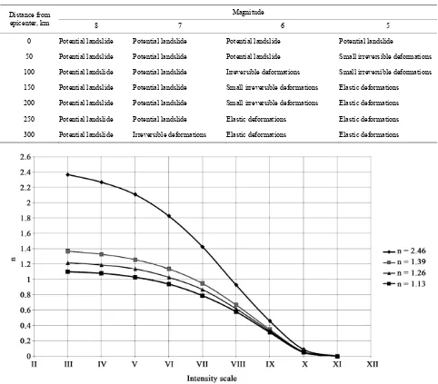
[image:7.595.57.539.298.721.2]odels with n = 1.13, 1.39 and 2.46, and inclination angles of sliding plane were equal to 22, 18 and 10.5 degrees, respectively. Pseudostatic estima-tions of safety factor for slope models are presented in
Figure 8. As is easily seen, these estimations are very
close to the estimates of slope stability for natural condi-tions (Figure 1). Vibrations with intensity up to level
IV-V nearly have no influence on stability that conforms to experimental data (Table 3). It is important to note
that according to these estimates to the earthquakes of level IX even the operating slope with safety factor more than 2 would not resist.
Comparison of the obtained data on time of displace-
Table 5. Estimation of probable afte ffects of earthquakes (h < 50 km) of various magnitude for open-pit mine slope with safety factor n = 1.26.
Magnitude
to
(4) and (5) one can estimate for given conditions the probable
For more common estimation of influence of seismic effect on open-pit slope stability additional tests were carried out for slope m
re
Distance from
epicenter, km 8 7 6 5
0 Potential landslide Potential landslide Potential landslide Potential landslide
50 Potential landslide Potential landslide Potential landslide Small irreversible deformations
100 Irreversible deformations Small irreversible deformations
ntial landslide Small irreversible deformations Elastic deformations
200 Potential landslide Potential landslide Small irreversible deformations Elastic deformations
250 Potential landslide Potential landslide Elastic deformations Elastic deformations
300 Potential landslide Irrev ble deformations Elastic deformations Elastic deformations Potential landslide Potential landslide
150 Pote Potential landslide
ersi
[image:7.595.55.542.304.714.2]m
r vibrations of level VIII the preparation time already
c. is overcome with n = 0.6.
phs of displacements for slopes w nitial safety factor under various intensity of vibrations for earthqua s of magnitudes 6 an .
4. Re
me
Analy f dat th i tions
of level VI, induced earthquakes of magnitude 5 or 6, it is quite sufficie tand r 1.3
[4], bu wev e in ions,
but ind by rem qua s
7 or 8 s req se i up to
1.35 - With rati
r support of slope stability under any magnitude it is equied safety factor not less than 1.4. For intensity of level VII such value of safety factor is not only necessary, but also sufficient.
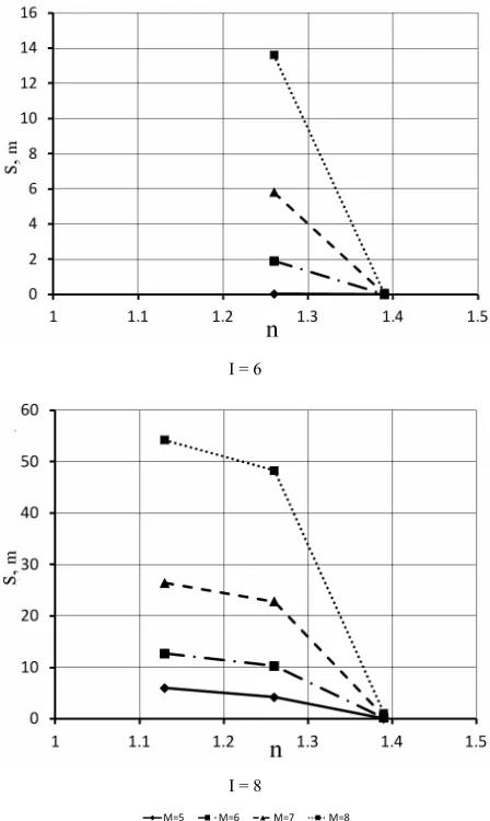
As to vibrations of level VIII, the matter is more com-plicated (see Figure 10). Under long-duration vibrations
(an earthquake of magnitude 7 or 8) substantial irreversi-ble deformations, 0.5 - 1 m, occur, which threaten later with potential landslide during new seismic and seismo-explosive effects Therefore, in such cases it is advisable to increase the safety factor to 1.42 - 1.45.
It should be specially considered the catastrophic brations I = X-XII. It is quite obvious that with such vi-brations it would be impossible to hold the not operating slope from landslides with any competent safety factors. As experiments show, however, even with intensity of vibrations I = 11 and of magnitude 7-8 the operating slope with safety factor 2.3 will experience noticeable irreversible deformations, s = 0.3 - 1.2 m, but, however, conclusion from pseudostatic calculation on inevitable landslide (n = 0!) is not verified.
As an example, quote the recommendation on selec-tion
pen
ent preparation with calculated safety factors has shown a sharp decrease of time of preparation with small and moderate intensity of vibrations and begins in the vicinity of the field of approximate equality of holding and mov- ing forces, n1. For example, for intensity of level VII a sharp decrease in preparation duration up to 1 sec. and below takes place with original value of n within 1.2, i.e.
for pseudostatic safety factor about 0.9. At the same time fo
[image:8.595.311.535.88.463.2]substantially diverges with pseudostatic calculation—time delay threshold of 1 se
Figure 9 shows gra
ith different i
ke d 8
com
ndations
sis o a shows that wi ntensity of vibra
nt to have the s ard safety facto t, ho er, with the sam tensity of vibrat uced
, it i
ote heavy earth uired the increa
kes of magnitude n safety factor 1.4. intensity of vib ons of level VII-VIII
I = 6
fo r
of necessary safety factor for open-pit slopes and casts with weak contacts under seismic effect, Table 6.
o
5. Conclusions
Based on data obtained in experiments, one may formu-late the following recommendations for the determina-tion of parameters of open-pit slopes in seismoactive zones.
I = 8
Figure9. Graphs of displacements for slopes with different initial safety factor under various intensity and magnitude of earthquakes.
Fi
earthquakes of different magnitudes.
[image:8.595.310.536.518.705.2]Table 6. Recommendations for selection of safety factors for open-pit slopes and opencasts in seismoactive zones.
Magnitude Intensity
scale
8 7 6 5
8 1.42 - 1.45 1.4 1.4 1.4
7 1.4 1.4 1.4 1.35 - 1.4
6 1.35-1.4 1.35 - 1.4 1.3 1.3
—In estimation of influence of seismic effect on open- pit slope stability it is necessary to account not only the intensity of vibrations, but also the magnitude of earth- quake, which induced them, because just a magnitude first of all has an impact on duration of vibrations. Rec- ommended safety factors during intensity of vibrations V-VIII and an earthquake of magnitude 5 - 8 are within the range of standard value 1.3 to 1.42 - 1.45.
—Practical realization of the developed method for selection of safety factor in seismoactive zones should be based on the detailed microseismic zoning, and also on the location of lineaments revealed by V.I. Ulomov, in generalized view representing axes of 3D seismoactive faulted or displaced structures and potential origin of earthquakes, indicating the most dangerous sites (focus) of lineament structure [42].
Hence, in the basis of calculations of necessary safety factors should be laid not only maps of intensity of vibra-tions (OSR-97A and OSR-97B), but also structural maps of location of earthquake origin and seismodangerous lineaments. In major mining zones (first of all, at Kuz-bass, the Kola Peninsular and the Urals) the location of seismogeneous lineaments should be revised, based on observations of technogenic seismic activity and analysis of geodynamic processes at coal- and ore mines.
To the significance of account of location of potential rthquakes additionally the following ate, the study of which seems to be
servation point not only the total duration of vi-brations will increase, but also the prevailing period that, how our investigations have shown, will lead to the rise of influence of vibrations on open-pit slope stability;
—In this investigation consideration was given only to most widely distributed crustal earthquakes, but, how-ever, less widespread heavy deep earthquakes have, as a rule, great periods of vibrations and large zones of influ-ence, and so they represent the specific hazard for open- pit slopes.
With absence of data on structure of lineaments and potential location of earthquake origins, and also due to absence of data on microseismic zoning (quite possible
situation at the stage of feasibility study and preproject development), it is necessary to apply the standard maps OSR-97, presented in SP7P 11-7-81, and preparatory materials OSR-2012 [42], but, however, it is desirable, as possible in more details, to estimate the probable vibra-tions of various intensity.
REFERENCES
[1] “Construction in Seismic Zones,” GOSSTROI RUSSIA, Moscow, 2010, 88 p.
[2] Università degli Studi di Milano, “Methodical Instruc- tions for the Determination of Inclination Angles of Slopes, Pit Banks and Waste Banks of Open-Pits Being unde Construction and Explo ,” Leningrad, 1972, 165 p. [3] Università degli Studi di Milano, “Methodical Instruc-
tions for Calculation of Stability and Bearing Capacity of Pit Dumps,” Leningrad, 1987, 123 p.
[4] Università degli Studi di Milano, “Regulations for Sup- port of Coal Open-Pit Slope Stability,” St. Petersburg, 1998, 208 p.
[5] “Recommendations for Selection of Methods for Calcula-tion of Safety Factor of Slope and Sliding Pressure,” Ministry of Mounting and Special Construction Works of Ukraine, TsBNTI, Moscow, 1986, 124 p.
[6] Hydro-Project, “Recommendations for Calculation of Sta- bility of Rocky Slopes,” Moscow, 1986, 52 p.
[7] E. P. Yemelyanova, “Basic Regularities of Sliding Proc- esses,” National Electric Drag Racing Association, Mos- cow, 1972, 310 p.
[8] M. A. Revazov and T Pustovoitova, “Account o Seismic Forces in Calc ns of Open-Pit Slope Stabil- ity Located in Seismohazardous Zones,” Proceedings
lov, “Seismoresistance of Ground Founda- tions,” Tashkent, 1984, 192 p.
[10] A. H. Sadykov, “Sliding Stability of Forest Slopes and Banks under Effects,” Ph.D. Thesis, Institute Seismology G. A. Mavlyanova Uzbek Academy of Sciences, Tash- kent, 2011, 19 p.
[11] O. A. Kusonsky and A. N. Gulyaev, “Possible Trigger Effects of Some Earthquakes of the Urals,” The Urals Geophysical Vestnik, No. 6, 2004, pp. 74-80.
[12] O. V. Zoteev, “Geomechanics: Educational Textbook,” UGGGA, Yekaterinburg, 1997, 128 p.
[13] Y. P. Astafyev, R. V. Popov and Y. M. Nikolashin, “Con- trol of Rock Mass State in Surface Mining of Mineral Deposits,” High School, Kiev, 1986.
[14] P. S. Mironov, “Explosions and Seismic Safety of Con- structions,” National Electric Drag Racing Association, Moscow, 1973, 186 p.
[15] S. V. Medvedev, “Seimics of Mining Explosions,” Na- tional Electric Drag Racing Association, Moscow, 1964,
origins of heavy ea circumstances indic
the natural way to continue and progress of present in-vestigations:
—With magnitude growth and remote far earthquakes from ob
r itation
. K.
ulatio f
Research Institute of Mining Geomechanics and Mine Surveying (VNIMI), No. 67, 1967, pp. 313-318.
[9] H. Z. Rasu
188 p.
ol. 24, No. 4, 1974, pp. 661-665.
.1680/geot.1974.24.4
versus Static Factor of Safety in Stability Analysis of Earth Dams and Embankments,” Geotechnique, V
doi:10 .661
[17] E. Hyne nd A. G. Franklin, “Rationalizing the Seismic Coefficient ethod,” M cellaneou aper -84- y Corps of Engineers Waterw
Ex-, 1984Ex-, 21
[18] Earthquak
sign o nd ams, otechniq
29, No. 3, 1979, pp. 215-263. M. s-Griffin a
M is s P
GL 13, US Arm , Vicksburg
ays periment Station p.
H. B. Seed De
, “Consideration f Earth a
in the Rockfill D
e-Resistant
ue, V
” Ge ol.
doi:10.1680/geot.1979.29.3.215
[19] N. R. Morgenstern and V. E. Price, “The Analysis of the Stability of Generalized Slip Surfaces,” Geotechnique, Vol. 15, No. 1, 1965, pp. 79-89.
doi:10.1680/geot.1965.15.1.79
[20] N. M. Newmark, “Effects of Earthquakes on Dams and Embankments,” Geotechnique, Vol. 15, No. 2, 1965, pp. 139-159. doi:10.1680/geot.1965.15.2.139
[21] R. W. Jibson, “Predicting Earthquake-Induced Landslide Displacements Using Newmark’s Sliding Block Analy- sis,” Transportation Research Record 1411, 1993, 17 p. [22] G. Saygili and E. M. Rathje, “Empirical Predictive Models
for Earthquake-Induced Sliding Displacements of Slopes,”
Journal of Geotechnical and Geoenvironmental Engi- neering, Vol. 134, No. 6, 2008, pp. 790-803.
[23] J. D. Bray and T. Travasarou, “Simplified Procedure for Estimating Earthquake-Induced Deviatoric Slope Displace- ments,” Journal of Geotechnical and Geoenvironmental Engineering, Vol. 133, No. 4, 2007, pp. 381-392.
doi:10.1061/(ASCE)1090-0241(2007)133:4(381)
[24] S.-Y. Hsieh and C.-T. Lee, “Empirical Estimation of the Newmark Displacement from the Arias Intensity and Critical Acceleration,” Engineering Geology, Vol. 122, No. 1-2, 2011, pp. 34-42.
doi:10.1016/j.enggeo.2010.12.006
[25] J. Graham, “Methods of Stability Analysis,” In: D. Brundsen and D. B. Prior, Eds., Slope-Instability, Wiley, New York, 1984, pp. 523-602.
[26] D. Pradel, P. M. Smith, J. P. Stewart and G. Raad, “Case History of Landslide Movement during the Northridge Earthquake,” Journal of Geotechnical and Geoenviron- mental Engineering, Vol. 131, No. 11, 2005, pp. 1360- 1369. doi:10.1061/(ASCE)1090-0241(2005)131:11(1360) [27] V. S. Zakharov, D. A. Simonov and A. I. Koptev, “Com-
puter Modeling of Seismogeneous Landslide Move- ments,” Electronic Scientific Edition “GEO Razrez”, No. 1, 2009, 24 p.
http://georazrez.uni-dubna.ru/download/2009/03/Zakharo v-CompModel_Seysmogennykh_Opolznevykh_Smesche ny.pdf
[28] S. L. Kramer, “Geotechnical Earthquake Engineering,” Prentice-Hall, Upper Saddle River, 1996. 694 p.
[29] S. L. Kramer and M. W. Smith, “Modified Newmark Model for Seismic Displacements of Compliant Slopes,”
Journal of Geotechnical and Geoenvironmental Engi- neering, Vol. 123, No. 7, 1997, pp. 635-644.
doi:10.1061/(ASCE)1090-0241(1997)123:7(635)
[30] N. Ambraseys and M. Srbulov, “Earthquake Induced Displacements of Slopes,” Soil Dynamics and Earthquake Engineering, Vol. 14, No. 1, 1995, pp. 59-71.
doi:10.1016/0267-7261(94)00020-H
[31] A. M. Mochalov, “Prediction of Deformations of Open- Pit Slope by the Results of Observations and Modeling of Slopes,” Proceedings Research Institute of Mining Geo- mechanics and Mine Surveying (VNIMI): Study and Pre-diction of Mo ons of Rocks, Hy-drogeomechanical Processes in Deposit Mining with
Association, Len-
red Rocks,” National Electric Drag Racing
l Problems of
ound Conditions of Seismic Hazard,
of
” In: Seis-
erent Complicated
eretokin, “On Actuality of Stan-
. 44-53.
vements and Deformati
Underground and Surface Methods, Leningrad, 1991, pp. 119-124.
[32] G. M. Lyakhov, “Principles of Dynamics of Explosive Waves in Ground and Rocks,” National Electric Drag Racing Association, Moscow, 1974, 192 p.
[33] M. P. Mokhnachev and V. V. Pristash, “Dynamic Strength of Rocks,” Nauka, Moscow, 1982, 141 p.
[34] E. S. Romm, “Structural Models of Porous Space of Rocks,” National Electric Drag Racing
ingrad, 1985, 239 p.
[35] M. V. Rats and S. N. Chernyshov, “Fracturing and Prop- erties of Fractu
Association, Moscow, 1970, 164 p.
[36] F. F. Antikaev and N. V. Shebalin, “Revision of Correla- tions between Level of Macroseismic Effect and Dynamic Parameters of Ground Movement,” Journa
Engineering Seismology: Investigations on Seismic Haz- ard, No. 29, Nauka, 1988, pp. 98-108.
[37] V. V. Schteinberg, “Quantitative Characteristics of Ground Vibrations during Heavy Earthquakes,” In: Estimation of the Influence of Gr
Nauka, 1988, pp. 12-35.
[38] A. M. Mochalov, “Estimation of Open-Pit Slope Stability by Observable Deformations,” Proceedings Research In-stitute of Mining Geomechanics and Mine Surveying
(VNIMI) Improvement of Methods for Calculation Movements and Deformations of Rocks, Structures and Open-Pit Slopes in Coal Seam Mining under Complicated Geological-And-Mining Conditions, Leningrad, 1985, pp. 42-52.
[39] N. V. Shebalin, “Relationship between Magnitude and Intensity of Earthquakes Depending on Depth of Their Origin,” Bulletin of the Seismological Society of America, No. 6, 1957, pp. 122-126.
[40] N. V. Shebalin, “Methods for the Use of Engineer- ing-Seismological Data in the Seismic Zoning,
mic Zoning in the USSR, Part 1, Chapter 6, US Depart- ment of Commerce, Moscow, 1968.
[41] N. P. Abovsky, V. G. Sibgatulina and K. V. Simonov “Development of the System of Geotechnology for Seis- mic Resistant Construction under Diff
Geodynamic Ground Conditions,” The Siberian Federal University, Krasnoyarsk, 2008, 172 p.
[42] V. I. Ulomov and S. A. P
![Figure 1. Chart of general seismic zoning of the North Eurasia OSR-97 [1] with marked coal opencasts on it](https://thumb-us.123doks.com/thumbv2/123dok_us/9949092.496452/2.595.59.536.414.720/figure-chart-general-seismic-zoning-north-eurasia-opencasts.webp)