Abstract— It is challenging for facial recognition technology to recognize a person correctly. It is even more challenging when trying to recognize a person if this person is showing any form of facial expression. Facial expressions deform the face in various ways. The facial recognition technology of today will perform worse while a person is showing these kind of facial expressions. In this research we will take a look at the possibilities to compensate facial expressions. The research consists of two parts. The first part being creation of a new database for facial expressions. This database will contain alternated frames, which will give us more insight in the deformation of the face. The database also ensures us for a smooth as possible deformation for warping. The second part being the actual compensation of facial expressions. This will be done through image warping.
I. INTRODUCTION
he human face is full of expressions and emotions. Humans can be happy, sad or disgusted for example. All these facial expressions deform the face to a different state than it was in before. Humans, but also animals, use these facial expressions as a form of communication to each other.
People still recognize another even while they are showing any form of facial expression. However there is a downside on these facial expressions when it is coupled to facial recognition. It is known that these facial expressions affect the performance of facial recognition. A person is less likely to be recognized if his or her face shows any form of expression.
So what to do about this problem?
To increase the detection rate we want to compensate these facial expressions. This compensation will take the expression out of the face. If a facial expression is compensated within the face, the face should be expressionless or in neutral state. Facial recognition software should have an easier time recognizing the person if all went well. When ideally compensated, a person should be equally recognized from a neutral expressionless image and a facial expression compensated image from someone laughing for example. But before starting on compensating these facial expression we first need to know what facial expressions are.
Facial expressions
Facial expressions are a form of human communication. A facial expressions is made by one or more motions of the muscles in the face. In the facial action coding system movement of one or more facial muscles are called action units or AU’s. Ekman and Friesen defined this Facial Action Coding System (FACS). This system makes for a clear, compact representation of the muscle activation of a facial expression. [1] This coding system is given by a set of AU’s. For example AU 4 defines the contraction of two muscles resulting in the lowering of the eyebrows, while AU 7 defines the eyelid tightening. All AU’s are seen in different expressions. AU 4 for example is an AU that can be seen a lot in expressions like sadness, fear and anger. All these AU’s are described in other researches. [2]
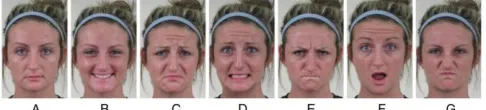
[image:1.612.313.556.469.524.2]All facial expressions have their own set of AU’s combined. Some combinations are of known category like facial expressions of emotion. Happy or sad are well-known emotions. Each set of AU’s is a new type of facial expression. There are a lot of possible facial expressions that can be formed with all of these AU’s put together.
Figure 1: Sample images of a face showing different facial expressions of emotion: (A) Neutral, (B) Happy, (C) Sad, (D) Fear, (E) Anger, (F) Surprise, (G) Disgust
In this research we will be just looking at a few facial expressions of emotion: Happy, Sad, Fear, Anger, Surprise and Disgust. These are the six known basic emotions. All of these six emotions are part of facial expressions. These emotions are a state of facial expressions. By narrowing it down to just these basic emotions, we have an overall picture of what is possible. If the compensation works on these basic emotions (or even on one) it could potentially be working on all facial expressions when the compensation is enhanced. It just has to be programmed correctly in the software for each AU separately. This research will be focusing only the necessary AU’s for
Facial expression compensation
Kevin Selman
Supervised by: Luuk Spreeuwers, Raymond Veldhuis
SCS group, University of Twente
Enschede, The Netherlands
compensation. All the other AU’s will be skipped if they aren’t needed. They could, however, be added in the future.
Table 1: Common AU's in each basic emotion
Category Common AU’s
Happy 12, 25
Sad 4, 15
Fear 1, 4, 20, 25
Angry 4, 7, 24
Surprised 1, 2, 25, 26
Disgusted 9, 10, 17
Above are the common AU’s used in with each of the basic emotions. There are several other AU’s that could be important too. For the emotion happy AU 6 (lip parting) sometimes occurs too, but isn’t a must. Another research shows the full list of AU’s with a list of 21 different categories where they FACS coded their database. [3] Their research also shows all the common AU’s shown and the less common shown AU’s with percentages of the subjects using those. It shows the most common key points on the face to be compensated, which is useful in this research. We will be mainly looking at the common AU’s that have to be compensated for a facial expression.
II. IMAGE WARPING AND TRANSFORMATIONS
2.1 Image warping
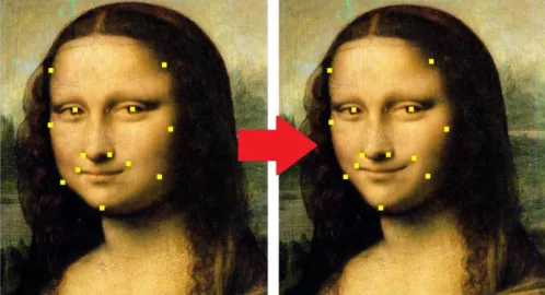
[image:2.612.47.298.107.195.2]To compensate the facial expressions, image warping is used. Image warping is a process of digitally manipulating a graphical object in such a way that any shapes portrayed in the image have been significantly distorted. This image warping will cause continuous deformation of this graphical object. By using image warping, an image can be manipulated and deformed in such a way that a facial expression is no longer present. All the deformations are made by different transformations in the image.
Figure 2: Image warping, Mona Lisa
2.2 Transformations
To deform an object or image several transformations are used. A transformation is a method to ‘transform’ or ‘translate’ point mappings from one coordinate system to another. Transformation, for example, maps the original points (x1, y1)
in one coordinate system to new points (x2, y2) in another
coordinate system.
There are a few simple transformations we will take a look at first: Identity, translation, rotation and isotropic scaling.
Figure 3: Simple transformations
Identity transform will transform an object with the exact same point mapping. So in other words, the object doesn’t change. The object will be exactly the same before as after the transform.
The identity transform is needed for the points or objects that don’t change and stay at the exact same spot after
transforming as it was before the transform. This identity transform is defined by:
|𝑥𝑦2
2| = |
𝑥1
𝑦1|
In this formulation x2 and y2 are the newly transformed
coordinates and x1 and y1 are the old coordinates. For identity
transform both x-coordinates and both y-coordinates will have the same value.
Translation is a function that moves all coordinates of a point map in a constant distance in a specified direction. With translation a picture can be moved in various directions. Translation is used for the moving points from one spot to another.
|𝑦𝑥2
2| = |
𝑥1
𝑦1| + |
𝑡𝑥
𝑡𝑦|
In this formulation tx and ty are the translation values. The new
coordinates (x2 and y2) are the old coordinates (x1 and y1) plus
these translation values. The new transformed object will be moved with a value of tx over the x-axis and a value of ty over
the y-axis.
Rotation is a transformation function for rotating the point map with a specified angle. The object will rotate to the left or to the right.
Rotation is used to add an angle to an object. Some points have to be rotated in order to get a correct transformation. Rotation can be described in coordinates as:
|𝑥𝑦2
2| = |
cos 𝜃 − sin 𝜃
sin 𝜃 cos 𝜃 | ∗ |
𝑥1
𝑦1|
The value 𝜃 is a radian value. Picking a value of 𝜃 =1
4𝜋 for
example will rotate the object 45 degrees to the left.
Isotropic scaling, or also called uniform scaling, is a linear transformation that scales the original point map with a constant to a new point map. All values of the old point map will be multiplied with the constant to get the values for the new point map. This enlarges or shrinks the objects by the scaling constant.
[image:2.612.48.297.494.629.2]|𝑦𝑥2
2| = 𝑐 ∗ |
𝑥1
𝑦1|
With c being a constant. The old coordinates will be multiplied by this constant to get the new coordinates.
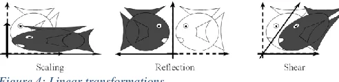
All of these simple transformation together form the basics of the similitudes transform. There are some more linear transformations: Anisotropic scaling, reflection and shear.
Anisotropic scaling, or also called non-uniform scaling, is a transformation that scales the old point map with a constant to a new point map. The difference with uniform scaling is, that there is a scaling factor for each axis direction. An object could be stretched over the x-axis by a factor of 5, while the object is not stretched (factor 1) over the y-axis. It scales the object over an axis with different scaling factors instead of scaling the whole object at once by one scaling factor. Anisotropic scaling can be written down as:
|𝑥𝑦2
2| = 𝐴 ∗ |
𝑥1
𝑦1|
[image:3.612.314.566.239.356.2] [image:3.612.48.294.367.427.2]With A being the matrix with scaling values:
𝐴 = |𝑠0𝑥 𝑠0
𝑦|
In matrix ‘A’ the values sx and sy are the scaling values
corresponding to the x- or y-direction.
Figure 4: Linear transformations
Reflection is a function that mirrors an object in an axis, point or line. Another term is flipping. The complete point map will be mirrored with new values, depending on the reflection axis. The complete object will be flipped over the reflection axis.
Shearing changes the angle between axis. By using shearing, an object can be deformed with an angle over a single axis. This will however get a distorted object while using it for face transformations. Shearing should not be confused with rotation. Shearing will change all angles, except straight angles, between a set of points. Shearing will also change the length of line segments that are not parallel to the direction of displacement. There are two ways for shearing: horizontal shearing and vertical shearing. For horizontal shearing the x-axis isn’t moved. All the horizontal lines are moved to the left or to the right, depending on the shearing factor. For vertical shearing the y-axis isn’t moved. All the vertical lines of an object are moved to the left or to the right, depending on the shearing factor.
|𝑥𝑦2
2| = 𝐴 ∗ |
𝑥1
𝑦1|
With ‘A’ being the shearing matrix. For horizontal shearing this matrix can be written as:
𝐴 = |1 𝑚
0 1|
With a positive value for ‘m’ the object shears to the right and with a negative value for ‘m’ the object shears to the left. For vertical shearing this matrix can be written as:
𝐴 = |1 0
𝑚 1|
With a positive value for ‘m’ the object shears up and with a negative value for ‘m’ the object shears down.
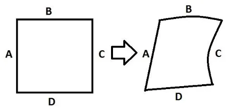
All these transformations together form the basics of affine transformation. Affine transformation can be written down in general form for 2D transformations as:
|𝑥𝑦2
2| = 𝐴 ∗ |
𝑥1
𝑦1| + 𝑏
With ‘A’ being a matrix and ‘b’ being a vector.
We will be using affine transformation as the basics for the transformations.
Figure 5: Affine transformation
For the transformations to be looking quite real, we want it to be it as rigid as possible. This is an algorithm keeping the object transformed closer to reality instead of making it surreal [4][5][6]. Rigid or Euclidian transformation will have less methods of transforming, but the transformations used will keep the warped object closer to reality. This is important for transforming human faces. We want to keep these close to reality instead of getting strange and unreal picture after warping. Translation, identity and rotation will keep the original picture close to its original shape. Reflection should be avoided. Reflection isn’t needed in this case. The left part of the face is different than the right part. By reflecting, both sides will be swapped. The face is not the correct one anymore. So it has to be reflected or mirrored again to get to a good image. It takes time, without having any useful effect in this case.
Figure 6: Transformation
The idea is to have a transformation from one state to another. If we have a correct transformation, we could also be using an inverse transform to transform it back to the original point mapping. All the points within the surface will be transformed to a new mapping.
[image:4.612.54.284.338.441.2]As for a grid transformation this could be really useful. The edges are the chosen points that will be moved. Those points are the crossings of the grid lines in the grid. All the points within the edges will be transformed in a specified manner. These points will move along as the transformation is applied.
Figure 7: Transformation of a point within the surface
The red lines are the x-axis and y-axis for a single point within the surface. The crossing of this line is the point itself. With α and β being two opposite angles at this crossing. We can write down a weighted transformation for a single point within the surface:
T → α ∗ C + (1 − α) ∗ A + β ∗ B + (1 − β) ∗ D Such a transformation can be applied for all points. The values A, B, C and D are the weighted values for each of the lines around the enclosed surface. These values will be different depending on where the point is within the surface. A higher weighted value, means the influence of that line is greater than other. The point will more likely be closer to that line. When the transformation is applied to all points, the object is transformed.
2.3 Moving least squares
With our warping we will be taking a look at the moving least squares method.
The moving least squares (MLS) method was proposed by Lancaster and Salkauskas for smoothing and interpolating data. [7] Later on it was applied to image deformation as for smoothening image deformations.
Image deformation is based on a collection of points ‘p’ that will be deformed to a new position ‘q’. We call this
deformation function f. This function maps points in the non-deformed image to the non-deformed image. For f to be useful for deformations it must satisfy the properties: interpolation, smoothness and identity.
Moving least squares is a deformation technique that allows to compute a map f:R2->R2 from the transformation of a set of N pivot points p in the new positions q. The map f is smooth, preserves the identity (for q=p the map is the identity) and ensures that the points p are transformed in the points q (f(p)=q). [8]
2.4 2D vs 3D
Warping can be done in different dimensions. The more dimensions the more complicated the warping becomes. Every dimension adds new variables to take care of. Transformations in 2D, for example, only have to take X- and Y-coordinates into account, while Transformations in 3D have X-, Y- and Z-coordinates.
For warping a face we are choosing between 2D and 3D warping. A face itself is three dimensional. It has a height, a width and a depth. So to correctly warp a face all of these three variables should be used. We have to take all kind of deformations in all directions into account.
On the other hand most pictures taken are just saved with two dimensions (height and width). There is no depth information saved. Even though we can still convert these pictures to 3D using several other programs. This will, however, be an estimation and not the real depth information of the original face. Then there are several forms of 3D reconstruction too. For example a full 3D reconstruction of the face, or a flat 2D picture with an added dimension. The last one is pretty much the same as the 2D counterpart, except for the added dimension. This way the 2D picture can be
deformed not only in width and height, but also in depth. This could be useful for compensating some parts of the face. The hardest part is a smile with teeth shown. In 3D the teeth can be send to the back, while the lips are
The deformation between 2D and 3D warping might be roughly the same, it could still give a completely different result.
We will be focusing on 2D transformations in this research.
Table 2: 2D vs 3D warping
two dimensional (2D) three dimensional (3D) + Easier to transform - Harder to transform (more
variables)
+ Most pictures are in 2D - Less pictures taken in 3D - Only has width and height
information
+ Has depth information
- Less methods for compensating
III. DATABASE EXPERIMENT
The real experiment consists of two different parts. The first one being the creation of a new database and the second being the facial expression warping.
3.1 Database
We want to create a new database for this research. A database that contains the faces of different persons while looking straight into the camera. In other words: recordings of a face in front view. These different subjects are asked to perform a facial expression of emotion which will be recorded. There are several other databases containing this kind of data. The new parts in this database experiment are alternated frames to get more information out of it and capturing at higher frame rates to get a smoother transition.
Alternated frames means each first frame is taken in a different phase or state than each second frame. The phase or state swaps every next frame. By alternating frames, each phase or state can give us different information or purposes. The idea is to have half of the frames taken in normal light conditions, while the other is taken with High frame rate is preferred. Alternating frames loses half of the frames for a single phase. Next to that, we want high frame rates for better deformation of the face. While showing an emotion, the face will be deformed from a neutral expressionless face to a face with a facial expression of emotion. High frame rate will capture the deformation more precise, which could be used for gaining information in several ways. It could also be useful for image warping to use this database. Because the database contains a lot of frames from a face from neutral to
expression, the warping from expression to neutral could be done with smaller steps. The deformations between frames are smaller compared to straight image warping from expression to neutral. By using more frames, but with smaller differences, the transformations could be smoother. So more, but smaller transformations could have a positive effect on the image warping.
3.2 Projected grid vs marked grid
We are using an alternated frame setup. The first phase is a phase that will record the face in normal (lighting) conditions. The second phase could be used for different purposes. We want to get more information about the deformation of the face. There are several ways to more information about this. The method chosen is one with a grid. A grid could give information in several ways.
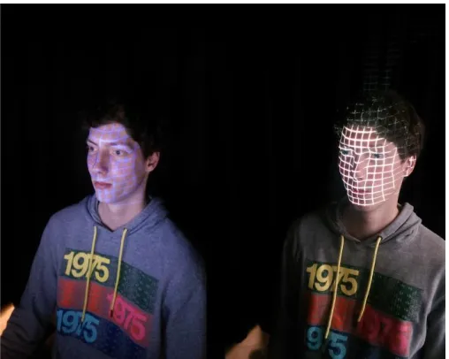
There are two different methods of getting the grid on the face. The first one is through projection. For projection a beamer or projector is used to project the grid on a face. This method is easy to use and easy to fit correctly on a face. The grid is not stuck to the face. So if a person moves, the grid won’t be following the face. The grid itself doesn’t change, the projected location does. Information about deformation is gathered by movement of face through the grid. Different facial parts could appear in different parts of the grid after deforming. This is movement of facial parts. Deformation to back or depth deformation is hard information to gather. The grid doesn’t change shape. This depth information is an important piece of information.
[image:5.612.313.567.129.332.2]To get alternated frames, the beamer or projector has to be synchronized with the camera. Each time the system is in second phase, the beamer or projector has to be turned on for that phase only (or off depending on the previous phase). It is possible, but could take a lot of work to get the beamer synchronized with the camera.
Figure 8: Marked grid (left) and projected grid (right)
The second grid method is by using markings on the face. By using the markers, the grid has to be drawn on the face. With this method the grid is stuck to the face. All the
deformations in the face will be traceable with this grid. While the recordings are just taken in 2D, the real face is still 3D. The deformation of the grid will follow the deformation of the (real) face.
When looking at it in 2D, we can see the lines of the grid changing in size. If something moves towards the camera, it will appear to be bigger. If it moves away from the camera, it will appear to be smaller. This is exactly the same as looking at an object. The further away this object is, the smaller it looks from your perspective. The closer the object is, the bigger it looks from your perspective. Movement sideways will have a little curve in the line. Movement to the left, gives a curve on the left. Movement to the right, gives a curve on the right.
This marked grid has useful extra depth information. This information can be used for a more precise compensation. The grid itself could be used in the idea of grid warping. A software package could filter out the marked grid to calculate the transform. The more precise depth information is one of the reasons why the marker method is preferred above the projection.
is hard to see any deformations in the face in depth. If there is a dimple for example or not, the full grid will stay the same.
Since the experiment involves video taken with alternating frames (one frame without grid and the next with grid), we have to take synchronizing frames into account. By projecting the beamer or projector has to be synchronized, while with the marked grid there are several other options. The idea for the marked grid is to use UV markers. These UV markers are only visible when UV light is shed on it. This fits perfectly with the alternating method: First frame normal light, second frame UV lights.
3.3 Camera
The camera that is used, is a ‘guppy pro F-125 C’ from Allied Vision Technologies.
The guppy pro F-125 is a FireWire camera (1394b) with ICCX445 CCD sensor. This camera has some pros on why to use it: It is easy to setup, easy to use, it is compact and light to easily fit in the experiment setup, it has a trigger input and can film in RGB format. Especially the trigger input is important, because the camera will be triggered externally from the light controller. Each phase shift will trigger the camera to take a single frame until the next phase shift occurs. There are also a few cons for this camera. Since the frames will be alternated between UV and normal lighting conditions, high frame rate is important. The frame rate of this camera is capped at 31 frames per second at full resolution of 1292x964. This
however is only for the Mono 8 format. Which isn’t the format we are looking for. Lowering the resolution to 800x600 and using RGB8 format the camera will be able to record at 30 frames per second. The format and frames per second are the minimal specifications needed for a good result. If the frame rate is lowered too much, the frames won’t have a smooth overlap. The frames per second is even halved if only looking at the frames taken in a single phase.
For the format, a format with good color reproduction is a must. The camera is installed in such way the face is fully shown in the frames. The video is shot in frontal view. No side view of the face was taken or any other
High resolution is preferred, but not a must. Higher resolution frames have more details in them and thus will get a more detailed video when all the frames are put together. The resolution has to be high enough to capture the full face and the deformations of the face made by facial expressions. High resolution is also preferred for better face recognition. [9][10] The 800x600 frames is high enough for this research.
3.4 Database recordings, plan of approach
In the experiment a camera with controllable lighting setup is used. A total of 6 normal lights and 2 UV lights will be used to get correct lighting conditions.
The lights are controlled in two different phases. In phase A only the normal lights will be turned on, while in phase B the normal lights and the UV lights will light up. The normal lights will always be on to get correct lighting of the face. Only in phase B the UV lights will shine light. This light will reveal any traces of UV markers. By using this method we can alternate the frames taken. First frame with normal lighting,
second frame with UV lighting, third frame normal lighting, fourth frame with UV lighting and so on.
By using this alternating method we get a full video
containing many separate frames. Half of the frames are from phase A and the other half are frames from phase B.
The frames from phase A, the normal lighting conditions, will be used for facial recognition and for applying warping to it. The frames from phase B, normal lighting with UV lights on, will be used to get more information about the deformation of the face in different states of emotion when starting from a neutral expressionless face. The first few frames are without any expressions.
A participant in the experiment is asked to sit right in front of the camera in a darkened room. The lighting conditions in this room can be controlled with the least amount of disturbance from other light sources. The distance between the camera and the tip of the nose of this participant is 8 meters. This is the sweet spot combined for the camera and lens. The height of the chair the participant is sitting on is adjusted to get a full fit of the face for the camera. With the distance and height of the chair adjusted correctly, the whole face is visible with a little bit of space left beneath the chin. So when yawning or showing any other facial expressions that pushes the chin down, the whole face including the chin will still be visible for the camera.
At first a beamer is used to project a grid on the face. The grid chosen is around 10x11 squares while covering the whole face. This grid is then traced with a UV marker. The traces of this marker can’t be seen under normal light conditions. However they will be revealed while UV light is shed on it. With the complete grid traced, it is time to start the recordings. The participant is asked to preform different facial
expressions. For this experiment the facial expressions are the six basic emotions: Happy, Sad, Fear, Anger, Surprise and Disgust. Each emotion is recorded in a 10 second video. The first few seconds the participant is asked to sit still without showing any facial expression. These frames can be used as a reference for a neutral expressionless face. After the first few seconds are over, the participant changes its neutral
expressionless face to one of the asked facial expressions of emotion. The participant tries to hold this emotions until the 10 second recording is over. The UV lights will stop blinking, which indicates the recording has come to a stop. This recording is then repeated for the remaining of the six
emotions. When all the emotions are successfully recorded, all emotions will be recorded a second time. This time the participant is asked to perform the emotions again, but now with the emotions a little more exaggerated. So in the second log of the recordings the emotions will pop out a little more. After this second set of recordings a total of 12 recordings will be captured.
The recordings will be saved in two different formats. The first as a lossless ‘.avi’ file. This is a lossless video format with all the 300 frames taken playable at 30 frames per second. It can be played and edited in different video player or video editing software. Half of the frames can be skipped to get a video from a single phase only.
a single workspace variable in uint8 format. This isn’t completely lossless, but still of high quality. By using the video player from Matlab all the frames can be seen apart from each other. All the frames can be saved individual for other purposes.
By skipping 1 frame each time and starting on the first or second frame, the full video can be seen from a single phase. Another option is to drop the frame rate to 15fps instead of the 30 fps. This will automatically make the program skip frames to get the desired frame rate.
IV. WARPING EXPERIMENT
4.1 Warping
Matlab is used as software package for programming. Matlab has a lot functions useful for this research. It is used in the data acquisition and in the warping part of this research. Data acquisition is done with the use of the Image acquisition tool in Matlab. Data can be recorded and analyzed through this tool.
All the basic functions for transforming an image can be programmed in Matlab. Several software packages within Matlab are used. Matlab can also import different functions. A few functions for testing MLS warping could be imported [11].
4.2 AAM / ASM
Active appearance model and Active shape model are useful ways for detecting a shape or a model. Active appearance model involves both a shape model and a texture model, while active shape model only involves the shape model. Both, AAM and ASM, can also be used for detecting a face or parts of a face. The main difference being AAM containing both a shape and texture model, while ASM only contains a shape model. A mouth, a nose, ears or the contour of the face can be detected. This can be useful to fit a model of a face to a picture containing a face. It can be used to know which parts of the face change with different facial expressions. Parts like the eyebrows and mouth are especially important. These bring a lot of emotion into the face. If these parts or even more parts of the face can be detected, it could be used for the
compensation. If these points are taken, it could be warped to a ‘neutral’ model with the same points.
[image:7.612.322.562.52.248.2]A 68-point mark-up from iBUG group was used as a warping model [12][13]. This facial point mark-up isn’t a must and any facial point mark-up will do if it has a correct fit on the face and enough facial points. This facial point mark-up however is directly ready for use on several databases.
[image:7.612.314.565.318.432.2]Figure 9: The 68 points mark-up used for annotations.
Table 3: 68 point’s mark-up linked to face parts
SHAPE POINT INDICES FACE PART 1 - 17 Cheeks and chin 18 - 22 Left eyebrow 23 - 27 Right eyebrow 28 - 31 Nasal ridge 32 - 36 Nasal base
37 - 42 Eyelids of the left eye 43 – 48 Eyelids of the right eye 49 - 60 Outer part of the lips 61 - 68 Inner part of the lips
Some of these facial annotation points won’t change when the face deforms. The nasal ridge for example will be at exact the same spot while smiling as it was before the facial expression. These points can be set to stay exact on the same spot, so they won’t be taken into account while warping.
This has to be done for every type of facial expression. The emotion ‘happy’ uses different AU’s than emotion ‘surprised’. Different facial landmarks are more important for different facial expressions.
4.3 Grid transform
[image:7.612.315.567.580.702.2]The second idea is warping using a transformation grid. This means warping a full grid to another grid or form. Just like AAM and ASM we have a grid that has to be transformed in different ways. The idea is to have a grid as reference grid. This grid represents the neutral expressionless face. If a face shows an expression, the changes of the grid can be
transformed back to this original neutral grid. This could work quite well. The only setback is, that every face is unique. Every face is unique. So every single person, needs its own neutral grid. Luckily this can be combined perfectly with the new database. Each person has its own grid in it. The grid only has to be detected by the software. If the grid is detected and turned into a model, the image warping program can easily apply image warping.
V. RESULTS
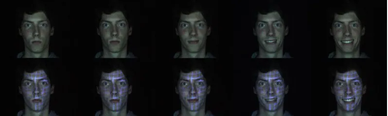
[image:8.612.333.545.227.386.2]5.1 Database Experiment
Figure 11: Result images showing different facial expressions of emotion: Neutral, Happy, Sad, Fear, Anger, Surprise, and Disgust
The database experiment was a start for setting up a new database. A few different persons participated in this database experiment. For each different person in the database a set of 12 ten-second movies were recorded. All the 6 basic emotions twice. All recordings were done twice to ensure the frames were captured correctly at least once. The pictures are clear and every frame is recorded.
The frame rate of the camera was capped at 30 frames per second. Unfortunately this was the maximal frame rate we could achieve. Higher fps is preferred, but there wasn’t a camera available meeting the required specifications.
It took the lights 1ms to start up. After the 1ms startup the frame took 32,3ms to be recorded. After the frame was captured, the phase swaps. At this point there is a 1ms startup time again. So a single phase takes 33,3ms to be captured. This phase time gets us to the 30 frames within 1 second. This 30 frames per second times a ten-second movie is 300 frames per movie. Each frame can be shown separately.
As said earlier, the frames captured are alternated. 150 frames are captured with normal lighting conditions, 150 frames with UV lighting conditions. The ones with normal lighting conditions can be used for image warping and facial recognition, while the others under UV lighting conditions can be used for research on deformations.
We can clearly see the deformation of the face while the participant is performing a facial expression.
5.2 Facial landmarks
[image:8.612.45.302.240.350.2]The first thing to make before warping was a program to tag our own facial landmarks or important points for the warping process. This was easily done with a few functions. It is able to grab the coordinates from a picture. It is all done by hand. It can be coupled to a model to get points automatically.
Figure 13: Facial landmarks
An example is the 68-point model as spoken of before. Or make a fit with another point model. This program saves the facial landmarks in a ‘.pts’ file. This can be opened in Matlab or any text processing program. It shows two values per row separated by a comma. The first value is the x-coordinate. The second value is the y-coordinate. This way each row has two values, which represent the landmark coordinates for the points. The number of rows is the number of facial landmarks given.
[image:8.612.108.507.596.716.2]5.3 Warping
Warping is done in 2D. Several methods were tried for a good warping program. The new form of grid warping unfortunately doesn’t work. So we can’t try to use that on the database experiment. The only warping program working so far is the one using MLS deformation.
This program tends to work best with the 68-point
annotations, since they are outlining the main key parts of the face. Therefore they are only warping the necessary parts of the face. The program itself still needs a user to complete several actions. It isn’t fully automated. The facial expressions of emotion, for example, aren’t automatically detected by the program. The user has to manually choose which facial expression of emotion is shown in an image. Each different facial expression has to be warped differently.
The warping program is still a work in progress. But it could be used to give a mere idea of the possibilities.
[image:9.612.47.300.266.352.2]First try is a test to warp a neutral image to the facial expression of emotion: happy.
Figure 14: Warping neutral to happy
This was done manually choosing the facial annotations one by one. The image warping shows a small change around the mouth. The warped image is now smiling a little. There aren’t a lot of strange deformations. In this case the program works for warping the image to a new state.
[image:9.612.44.301.494.583.2]So now we want to see if the warping works doing a full 68-point transformation from expression to neutral. For both states the facial annotations were set to get ready for image warping. We’re trying to warp a face with a full emotion right back to the neutral form.
Figure 15: Direct warping happy to neutral
The program tries to compensate the expression, but doesn’t fully succeed. The smile is partly compensated, but has strange deformations and the teeth are still visible. As said, this is a straight image warping from full expression to neutral in one shot. Taking smaller steps should work better. By taking more frames between full expression and neutral the deformations that have to be compensated are smaller. There are more steps needed, but every step just transforms a small part.
The results, however, in this case weren’t that good. The more, but smaller transformations had the opposite effect. The image wasn’t warped correctly and showed many incorrect
transformations. There could be two problems causing this. The first that could cause the image warping to fail is the head movement. The images used aren’t exactly a perfect fit on each other. The face moves a little to the left and right in the images. This head movement isn’t compensated yet in the warping program. This can cause the coordinates between frames to be different. There are several methods for compensating this head movement.
Another thing that could be the problem is the fitting of the model used. The points try to fit correctly on the face on each new frame. A new frame as a new fit of the point model used. Some points however could be wrongly placed if the fit isn’t correct.
5.4 Facial recognition
In this research facial recognition software is used for
comparing the results. We want to compare the warped images and the non-compensated image with a reference image. By using a facial recognition software package, it will tell us if the compensated images are better recognized by the software or not when compared to the non-compensated image. The software being used is FaceVACS from Cognitec [14]. FaceVACS has a simple clean web interface. A picture has to be uploaded, which will be compared with the data in its database.
Figure 16: FaceVACS
If the upload is done, it will put out a score and prints the name of the person it looks like the most. The scores from faceVACS are between 0 and 1. The higher the value, the better the person is recognized.
A reference image has to be added to the database in order to compare images with it.
Table 4: Emotion progression scores (faceVACS)
In the table on the left a few frames were taken from one person in the database with the facial expression of emotion being happy. This shows the progression from neutral to the state happy. T0 being neutral and T4 being the full expression. As seen the values are really close to each other. All the frames between neutral and full expression that aren’t taken in this table have around the same values. As for the other emotions it’s the same, except for the emotion disgust. All the frames between neutral and full expression still have the same values.
Happy
T0 0.999567
T1 0.999575
T2 0.999527
T3 0.999508
Table 5: Emotion scores, neutral to expression (faceFACS)
FaceVACS prints high scores for both the neutral and full expression. There was only one emotion that didn’t
correspond correctly. This was full expression of disgust. The facial expression deformed the face in such a manner, the facial recognition program had a harder time to recognize him. Eyes are almost closed, the mouth deformed and the head turned a little. All other emotions had such high for both the neutral face and image with facial expression in it. Everything between has similar scores. The facial recognition software works pretty well by itself. Even if any facial expression is shown.
We also tried uploading the warped images. These are uploaded to FaceVACS to see if the facial recognition software still recognizes the person correctly. The warped image from Figure 14 has a score of: 0.99952. This score is close to the neutral scores. The directly warped image from Figure 15 has a score of: 0.99449. This score is even higher than the score of the non-compensated image. The scores however are really close each other. We can’t draw any direct conclusions out of it. The only thing we can say is that the images are still recognized correctly by the facial recognition software faceVACS. If the images are deformed too much, faceVACS doesn’t recognize the person correctly anymore.
VI. CONCLUSION AND DISCUSSION
6.1 Conclusion
Is it useful to compensate facial expressions? Yes and no. It could be useful. To let a computer compensate the facial expressions by itself is challenging. Facial expressions can be described by coding systems like the FACS, but still every single person is unique. Every new face it recognizes has to be compensated differently. With every new face, the computer has to learn this new face first. The eyebrows could be lower or other parts will deform in a different way the system does not recognize. There are a lot of factors to take into account while compensating. So for the compensation software to work properly, extra research has to be done.
Unfortunately the grid transformation doesn’t work. This could be have been coupled to the new database set. This research has shown that there are possibilities though. There are a lot of good ideas for warping and other compensation methods, but not many have tried and succeeded correctly compensating facial expressions. The newly made database also opens up new ideas for future research on this subject. In the end, when there is a correct compensation of a facial expression, it could have a positive effect on the scores for facial recognition.
6.2 Discussion
As said compensation of facial expressions still has a long way to go. We have shown some basics ideas of this compensation of facial expressions. There are a lot of possibilities with compensation of facial expressions, but this is still not heard of a lot.
As for the database experiment goes, there are several ways to improve the quality of the recordings. First of all is a higher frame rate. An emotion can be ready within a second. Because of the alternating frame capture, we already lost half of the frames for a single phase. Next to it, some time passes after every frame. Lower fps means more movement can be seen between frames. We want the frames from both phases to be as close to each other as possible time wise. There has to be as little time as possible between each next frame. If higher frame rate can’t be achieved any movements in two frames following up each other should be compensated.
Another thing to look at is the UV marker setup. If chosen for the same setup with UV markers traced on the face, there could be chosen for a more precise way of putting it on the face like a stamp. It isn’t a must, since the first few frames (with the same drawn grid) will be used as reference. But it will give you better looking and more precise results. Next to that
The test subject could be moving his head sideways while filming. This is a minor setback if comparing frames 1 on 1. It has to be centered to the same fixed position again. Another way to solve this, is for the test subject to have a spot to lean its head against to keep it steady.
The database is quite small at this moment. There are only 2 subjects in it. To make it a good database, more persons have to be added. In the future more expressions can be added too.
For future work on warping there are several things to look at. The warping done is still in 2D. It gives us some problems with several parts of the face, like parted lips when someone is smiling. It is hard to compensate an open mouth. With 3D warping this could be compensated in a different way.
The grid warping is still just an idea. The warping program for this doesn’t work. The program has to be built from the bottom up again. With a grid-warping program there is a lot of potential. It could be coupled to the newly formed database too. This grid warping will, hopefully, give far better results. Sad Fear Anger Surprise Disgust
Neutral 0.999596 0.99957 0.999579 0.999584 0.999565 Full
Expression
REFERENCES
[1] Ekman P, Friesen WV (1978) Facial Action Coding System: A Technique for the Measurement of Facial Movement (Consulting Psychologists Press, Palo Alto, CA)
[2] Ekman P, Friesen WV (1976) Pictures of Facial Affect (Consulting Psychologists Press, Palo Alto, CA).
[3] Shichuan Du, Yong Tao, and Aleix M. Martinez (2014) Compound facial expressions of emotion, Proceedings of the National Academy of Sciences
[4] Igarashi, T., Moscovich, T., & Hughes, J. F. (2005,
July). As-rigid-as-possible shape manipulation. In ACM Transactions on Graphics (TOG) (Vol. 24, No. 3, pp. 1134-1141). ACM.
[5] Guo, H., Fu, X., Chen, F., Yang, H., Wang, Y., & Li,
H. (2008). As-rigid-as-possible shape deformation and interpolation. Journal of Visual Communication and Image Representation, 19(4), 245-255.
[6] Cuno, A., Esperança, C., Oliveira, A., & Cavalcanti,
P. R. (2007, May). 3D as-rigid-as-possible
deformations using MLS. In Proceedings of the 27th Computer Graphics International Conference (pp. 115-122).
[7] Lancaster, P., & Salkauskas, K. (1981). Surfaces
generated by moving least squares
methods. Mathematics of computation, 37(155), 141-158.
[8] Schaefer, S., McPhail, T., & Warren, J. (2006, July).
Image deformation using moving least squares. In ACM Transactions on Graphics (TOG) (Vol. 25, No. 3, pp. 533-540). ACM.
[9] Zou, W. W., & Yuen, P. C. (2012). Very low
resolution face recognition problem. Image
Processing, IEEE Transactions on, 21(1), 327-340.
[10]Gunturk, B. K., Batur, A. U., Altunbasak, Y., Hayes,
M. H., & Mersereau, R. M. (2003). Eigenface-domain super-resolution for face recognition. Image
Processing, IEEE Transactions on, 12(5), 597-606. [11] Gabriele Lombardi (2006),
http://www.mathworks.com/matlabcentral/fileexchange/1
2249-moving-least-squares/content/MLS/html/MLSDdemo.html
[12]C. Sagonas, G. Tzimiropoulos, S. Zafeiriou, M. Pantic. 300
Faces in-the-Wild Challenge: The first facial landmark localization Challenge. Proceedings of IEEE Int’l Conf. on Computer Vision (ICCV-W 2013), 300 Faces in-the-Wild Challenge (300-W). Sydney, Australia, December 2013
[13]C. Sagonas, G. Tzimiropoulos, S. Zafeiriou, M. Pantic. A
semi-automatic methodology for facial landmark annotation. Proceedings of IEEE Int’l Conf. Computer
Vision and Pattern Recognition (CVPR-W’13), 5th Workshop on Analysis and Modeling of Faces and Gestures (AMFG '13). Oregon, USA, June 2013 [14]Cognitec System GmbH (2014),
http://www.cognitec.com/facevacs-sdk.html
KEVIN SELMAN
Kevin Selman is currently studying electrical engineering at the