A DATA ABSTRACTION MODEL
M.M. RI DWAN
and
z.
LOY
Technical Report 78/1
April, 1978
Department of Computer Science
University of Canterbury
Christchurch 1
NEW ZEALAND
· Limited Distribution Notice:
This report has been submitted for publication elsewNere
and has been issued as a Research Report for early
dissemination of its contents. As a courtesy to the
intended publisher, its distribution is limited until
after the date of outside publication. It should not be
copied or extracted without permission of tha authors.
1.
ABSTRACT
An abstract model, called the. data abstraction
model, is proposed, and the basic DATAM constructs
and representations are presented.
The use of
DATAM in the modelling and representation of the
enterprise view of data is described.
The expressiveness of the data abstraction model
is illustrated with examples and the capabilities
of a DATAM model in subview formation and in
evolution are considered.
DATAM provides a basis for the analysis of data
models and analyses of the relational and network
models are discussed.
Key words and phrases
enterprise view of data,
concept abstraction, value abstraction, data
abstraction model, database design, .subview,
evolution, entity-relationship model, relational
model, network model.
1.
INTRODUCTION
~he enterprise view of data is the manner in which the
enterprise perceives its data resource.
The importance of a framework for the description of an
enterprise view of data has iately been recognized
(ANSI/X3/SPARC [1], Chen [7], Sibley and Kerschberg [16}).
Such a framework provides the necessary i!lterface for the
definition of a process to produce a good database design.
Models for the representation of data fall into two
types which will be referred to as abstract models and data
models.
An abstract modeZ is one which models the enterprise view
with objects which are direct representations ·of
distinct real world concepts.
A data modeZ is one which provides structural representations
for the instances of the associations between objects.
In the modelling of the real world, the concepts of the
reality must be related to the objects of the database.
The
relationship is specified in a stated perception of concepts
of the reality.
This stated perception or abstract model
(Biller and Neuhold [5]), provides the semantic reference
with which one is to vi~w the objects of the database.
The network and relational models (Date [10},
Fry and
2 •
Sibley (12)), among othe~s, have been proposed as representations
for the logical view of data.
One inherent weakness of these
data models stems from the fact that they do not stress the
enterprise view of data;
that is,
the abstract model or
real world perception reference is not clearly defined.
The approach of these data models has been to start from a
representation and then define conditions and operations on
the representation to refle9t the dynamics of some real
world concepts.
In such a situation it is not clear what
abstractions the model is meant to support.
An alternative approach is to create an abstract model
by identifying and defining formalized data concepts and
then proceeding to the representation, resulting in data
descriptions that are in much better accord with the
enterprise view.
An example of this abstract model approach
is Chen's entity-relationship model
[6]which begins with a
definition of formalized entity and relationship concepts
for the real world and then considers representations of
these conceptual objects.
In this paper we present
a
generalized data abstraction
model which is introduced in Section
2.DATAM is based on
definitions of formalize·d entity,
relationship and event
concepts.
Although these concepts are different from
those of Chen's, the data abstraction model can be viewed
as a generalization or extension of the entity-relationship
model.
Two examples in Section
2illu.strate the capability
of DATAM in modelling semantic information of the real world.
The abstraction of values for the representation and
storage of actual instances of the formalized concepts is
considered in Section 3.
Section 4 discusses consistent
3 •
subviewing of the abstract model allowing for the perception
of selected subsets of the· enterprise view.
In general, the enterprise perception of the world changes
over time.
To continue as an accurate representation of
this perception, the abstract model itself needs to evolve
· appropriately.
Section 5 discusses operations for th~
evolution of DAT.AM models.
Besides being aframework for data dei:;cription and
representation, DAT.AM can also be used in the analysis of data
models.
A DAT.AM interpretation and analysis of the
relational and network models is presented in Section 6.
2.
THE DATA ABSTRACTION MODEL (DATAM)
2.1 The Modelling Process
In discussing abstractions, it is necessary to distinguish
between the universe of real world objects and the universe
of database objects.
The modelling of the real world in
database terms centers around the modelling of the existence
and description of q_bj ects of the real world and the
association between these objects.
The descriptions and
relationships of objects in the real world vary in type
and extent with the state of the perceiver.
However,
database objects have to be unequivocally described and
have well defined associations at every instant.
Abstractions
serve this purpose by providing constructs with which the
database universe is to be defined.
The formulation of
different semantic constructs arises from the perception
of different types of associations and descriptions of
, objects in the real world.
In the modelling of data, multiple levels of views
of data or realms of interest (Biller and Neuhold [5],
ANSI/X3/SPARC [l]) can be identified.
The upper level
concerns ideas about the real world and the lower level
deals with the repr.esentation or recording of these ideas.
In the data a.bstraction model, basic formalized
constructs for the model are first formulated from a
perception and crystallization of real world concepts.
The
representation of and operations on these constructs ar~ then
defined. This collectic· of formalize<l constructs,
information structure and operations constitutes the data abstraction model presented here.
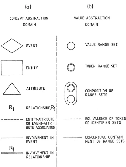
Ideas about the real world can be separated into two
areas - one concerning concept types and the other concerning the instance values of these concept types. These two areas will be referred to here as the concept abstraction and value abstraction domains respectively. The basic diagrammatic
representations used in DATAM are presented in Figure 1 which shows the representations for the formalized constructs at the concept abstractiqn domain and the representations of
value abstractions. The formalized constructs or concept abstraction types are described in this Section which also presents two modelling examples while value abstractions are discussed in Section 3.
2.2 Abstractions of the Reality
An abstract model is a "set of all abstract states which are abstractions of possible real world states" (BiJ.ler and
Neuhold [ 5]). In the data abstraction model we identify the following (concept) abstraction types or database constructs. 1. E~tity which mod~ls the existence of a real world object
and its capability of beingdescribed. 2. Attribute which represents the concept of the
description of an object where the
descriptor object is not itself described.
3. Relationship which repre8ents the concept of the mutual description or association between two entity or event types.
·;
.
4 • /(v c' 11 !, which models a descr ibahle object in which the object represents an association between two or more entity or event types.
Diagrammatic representations of these abstraction types and their associational connectives are given in Figure l(a).
Eacho[ the ahstraction types are considered in detail in this Section.
In this paper, tho. adjective database, or the prefix db- may be used to qualify an abstraction type (e.g.
database entity, db-attribute) to indicate that the
abstraction type of the model is meant. Generally, when no qualification is stated, the implied reference to the model or real world concepts will be clear from the context.
2.2.1 Entity. The most basic abstraction is that of the enlity which represents a real world entity. A real world entity (ANSI/X3/SPARC [ 1]) is "a person, place, thing,
concept or event, real or abstract, of interest to the enterprise". Within the database universe, an entity is perceived as a single, uniquely identifiable object. A real world entity set is a collection of real world entities
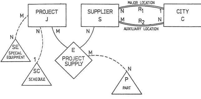
of the same type. In the abstract model, this is reflected by a database entity set which ~s a collection of database entity instances. Figure 2 illustrates a simple DATAM diagram for a "supply" model. The db-entity abstraction types shown for Project, Supplier and City represent the corresponding real world entity types of interest.
several attributes, representing the descriptions (properties, characteristics) of the real world object
which the database entity is representing. In the
real world an object perceived as a property (of another object) may also be viewed as an entity in its own right. An example is noZouP which may be used to desciribe an
entity, car; but colour itself may be an entity in that i t may be described by,- for example, wavelength. This multi-context use of the same object is always possible in the
real world. However, the contexts themselves are
well-defined. An object is a property when it is being used to describe another object; it is an entity when it itself is being described. Thus in the database abstractions, a database entity is described by db-attributes or,
equivalently, db-attributes describe a db-entity. Thus the role of a database object as attribute or entity in DATAM has a fixed context.
In Figure 2, Project is seen as an entity while
Special-Equipment and Schedule are seen as attributes as
8 •
they are not themselves described. The Project : Special-Equipment association, for example, represents the description
"requires Special-Equipment" and jndjcates the association
between instances of the Project entity to instances of the Special-F.quiprnent attribute. This mapping or association between Project, J, and Special-Equipment, SE, is shown as
m: n. F.or the model, this instance association can be
9.
2.2.3 Relationship. With the entity and attribute
abstraction types, a database object can then either be
describea or be a descriptor. In the real world,situations often arise where an object is both described as well as being a descriptor. The relationship abstraction type is introduced to reflect this associational concept. The description of an entity by another entity is differentiated from the
description by an at-tribute (see also Schmid and Swenson
[.15], Tsichritzis and Lochovsky [19]). The former is called
a database relationship. For example, a person may be
described by his relationship ("owns car") with a car which is itself perceived as an entity; while the description "has hair colour" is an attribute, as hair colour is not viewed as an entity here. Note that both attributes and relationships model the aonaept of describing. They are description types and correspond (in English) to verb phrases - e.g. "has colour", "owns car", "can be contacted by phone number", "is the spouse of". However, a relationship
facilitates an association between two entities, while the
association between an entity and its attribute is direct.
Thus there may be many relationships between any two entities, that is, the entities may describe each other in many ways, while an attribute represents only a single conceptual
description of a particular entity.
Figure 2 shows two relationships between Supplier,
s,
and City,c,
illustrating a multiple relationship sit~ation.Sand C describe each other through the relationships. For
f'X<'ITnple the 11 : 7 re] aLjonsld
r,
l \ , can be viewed as"SuppU ers S have major locations in Cities C" or the
inverse "Cities Care the bcations for Suppliers S".
10.
The other ( m: n) relationship, R
2, betweens and C indicates
"au~iliary location".
2.2.4 Event. The event abstraction type represents
the real world viewing of a description type as a describable
object. For example, the description type "owns car"
(person-entity: car-entity) may be viewed as the (event)
object "ownership of car" which might be described by, e.g.
"date of ownership", and "conditions of ownership". The
event "ownership of car'' is the noun dual of the verb phrase
"owns car" (Biller and NeUhold [ 4] ) •
The perception of a describable event implies cognizance
of the entities and the relationship from which the event is
derived.
An example of an event is shown in Figure 2. The event,
E, Project~supply, involves the entities Project and Supplier
and represents the perception of the (m:n) relationship
between Project J and Supplier Sas a describable object.
The event implicitly contains the relationship between J and
S. The event, E, is described by an attribute, Part,
representing the Part supplied in the supply to J by S.
The existence of event instances in the database does not
preclude the possible independent representation for the
corresponding database relationship. For example, separate
the event, E, of Figure 2 and the J:S relationship.
such a situation, both representations must develop
In
consistently. To avoid this potential integrity problem
(and also the inherent conceptual redundancy) the rule is made that where the database event is defined then the
implied assocations between the objects involved in the event is only available through the event and is not
independently defined as well. That is, tre specification of a database event contains the specification of its
corresponding relationships.
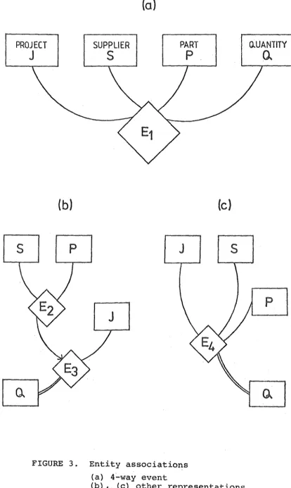
2.2.5 n-way event. Ann-way event may be composed
11,
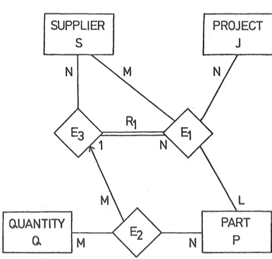
from n (n>2) objects. F6r example, Figure 3(a) shows a 4-way event representing an association between the entities Project, Supplier, Part and Quantity. Thisevent implies the
existence of the corresponding 4-way relationship between the four entities.
However, i t should be noted that any other) explicitly defined relationship between the objects of an event does not imply any associations with the event itself. For
example, in Figure 3(a), if a relationship, R
1, is
explicitly defined between J ands, then no association can be implied between this relationship and the event, E
1. The event of Figure 3.(a) may be differentiated
representationally into either Figure 3(b) or 3(c), among other possible diagrams. In Figure 3(b), the event E
] 2.
event B
3 representing the supply of P Ly S to J. ('l'he membership of E
2 in the event E3 is indicated by the arrow). The event E
3 has a relationship with the Quantity, Q. Figure 3(c) represents an event, E
4, of J-S-P which has a relationship with Q.
Each of the diagrams, Figures 3(a), (b) and (c) is con-sidered to contain the 4-way relationship between the
entities, J,
s,
P and Q. As they are shown, these three diagrams are equivalent conceptually over the totality of instances. Differences, however, become apparent when descriptions for a particular relationship are included.I t may be required, for example, to describe the relationship "the supply of P by S" by "regularity of supply". In this case, an association between the event E
2 of Figure 3(b)
and an attribute "Regularity of Supply" is formed. No other diagrams allow directly for this description. Thus, in the mod0lljng process, Figure 3(a) may be used when there are no
descriptions for the embedded relationships. When such descriptions exists the appropriate model (e.g. Figure 3(b),
3(c))
has
to be chosen. In the case where such a description is perceived and included later, Figure 3(a) may be evolved to the appropriate model to reflect the change in view. (Theevolution of data models is considered in Section 5). It should be stressed thatwhile the different models of Figures 3 (a), (b) and (c) contai.ns the same 4-way relationship
between the entities, each represents a different };:)erception. The choice of model is determined by the enterprise view and
2. 2. 6 Relationship and event definitions. Figure 3 also illustrates the reasons for the entity and event definitions made in Section 2.2.
As discussed above (Section 2.2.5), equivalent diagrams involving events and relationships can be constructed for a given number, n, of entities. All these models contain the direct n-way relationship between the entities. For example, Figures 3 ta), (b) and (c) contain the 4-way
relationship between the entities J,S,P and Q ...
The point to note is that the models in Figures 3(b) and 3 (c) have relatic;mships between only two objects.
13.
Since any n-way relationship can be perceived to be contained in a model which has events together with relationships
between only two objects, a construct for the direct
representation of a relationship of more than two objects is unnecessary. Because of this, and with economy of
concept in mind, a relationship is defined,therefore,to
exist between only two database describable objects (entities or events).
The definition of an event in Section 2.2 allows only
entities or events to be components of i t and precludes attributes. As an elucidation of this point, consider the case, for example, of the.event of Figure 3(a) but with
Supplier and Part beifig attributes instead of being entities. Then a later possible change to Figure 3(b) results in an event E
14.
the deiinition for a db-event allows only describable
objects (entities or events) to be members of it. It
should be noted that although attributes cannot be
components of an event, they can still be used to describe
an event (see, for example, Figure 2).
2.3 Illustrative Examples
To illustrate the concepts discussed, two examples of the
modelling process will be given here. For the first
example, an analysis of the relational~ entity-relationship
and DATAM model approaches is presented. The examples
demonstrate the expressiveness of DATAM in the modelling
of the real world.
2.3.l, Example 1. The following example, from Date
[10],
is consideredThe enterprise view concerns Teachers (T), Subjects (J)
and Students (S) and their associations. The perceived
associations are
1. For each Subject, each Student of that Subject is
taught by only one Teacher.
2. Each Teacher reaches only one Subject.
3. Each Subject is taught by several Teachers.
In terms of functional dependencies, the above statements
may be expressed as : ,
5C)1 ! 1 , ./ •
S, J -+ T
. l,., J•T -+ J .1
In the relational model, the representation of the above
15.
anomalies (Date [ 10]). Date gives a normalization solution
which involves decomposing the relation R (S,J,T) into the relations
Rl (S,T) and
R2 (!_,J).
In this case, however, the relations Rl and R2 now require some form of interrelation operators to maintain the semantics which is not indicated by the schema itself. rn·particular, conditions 2 and 3 above are represented by relation R2, but condition 1 is lost in the schema and becomes a user
responsibil,ity. For exampl~, let the instances of Rl and
I
R2 be as shown in Figure 4. The instances satisfy all
conditions. However, in the addition of tuple (Sl,T2) to the relation Rl, condition 1 (S,J+T) is violated. This violation is discernable only through validation with respect to
relation R2 and is not obvious from the relational schema. Using the entity-relationship diagram (Chen [6]), a model for the given example is shown in Figure 5. The given
conditions 2 and 3 are represented by the ER-relationship R3 and condition 1 is represented by the ER-relationship R4.
(The prefix ER- is used to distinguish concepts in the entity-relationship model from the concepts presented in this paper. Note also that the relationships R3 and R4 in
mapping conditions of the entity-relationship diagram. However, the first and fourth instances of R4 reveal an implied violation. An implied condition or consequence of condition 1 is that the Teacher for the Student of a Subject is the Teacher of that Subject. The instances,
(Jl,Sl,Tl) and (J2,S31Tl), imply that Tl teaches both
Subjects Jl and J2, violating condition 2. The entity-relationship diagram thus does not fully model the given
situation.
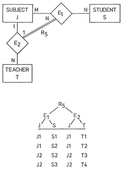
In DATAM, the semantic constraint in condition 1, that the Teacher involved is the Teacher of that Subject, can be specified explicitly as part of the model. This is possible because DATAM distinguishes between events and relationships, and allows relationships to be specified .between two events. The DA.TAM. model for the example is
16.
shown in Figure 6. The event E
1 represents the event that students take subjects, and event E
2 represents the event that teachers teach subjects in a manner (n:1 mapping)
satisfying conditions 2 and 3. The database relationship R
5 represents the relationship between events E1 and E2; that is, for each subject, each student taking that subject
(event E
1) is taught by only one teacher of that subject R
5 explicitly satisfies condition 1. Instances for the model are also given in Figure 6.
2. 3. 2 Example 2. This example involves a supply
(Project-Supplier-Part) model. The perceived associations are : ·
1 -...
-17.
1. A Supplier (S) supplies a Projett (J) with a Part (P)
in at most one Quantity (Q).
2. Each Supplier will only supply Parts in particular
Quantities; therefore, the Supplier in (1) is chosen from a set of Suppliers which supply that Quantity for that Part.
In terms of value associations, these can be expressed as:
1. S,,J,P
2, Q,P
m n
Note that the notation, : , indicates value (instance)
associations. For example, the second condition states that the set of allowable Suppliers,
s,
is determined by theQuantity of the Part required; or, equivalently that the Quantities of Parts that can be supplied is determined by the Supplier (with a m:n association of instances).
As with the first example, it is difficult to express this_situation accurately with most models. (In particular i t l~ads to a non-BCNF schema (Bernstein [3]) in the
relational model).
The DATAM diagram for this situation is given in Figure 7 . . Event E
1 represents the event of Suppliers,
s,
supplying Project, J with Parts, P. E2 represents the particular Quantities, Q of Parts. Event E
3 represents the supply of particular Quantities of Parts by a Supplier (condition 2). The database relationship R
1 represents the relationship, E
1 : E3 (strictly, F.1 n:
1
E
3), that the supply of Parts to a Project by a Supplier (Event E1) is of the correct Quantity
l 8 •
The above examples illustrate the capability of DA.TAM in the modelling of data. Situations involving multiple
associational criteria, such as in the examples, often occur in perceptions of the real world. Such situations are modelled straightforwardly in DATAM. The expressiveness
of DATAM facilitates accurate modelling of the real world. Constraints can be included in the model rather than be
3. VALlm ABS'T'RAC'T'InN
3.1 The Instances of Abstractions.
The modelling of the real world is the specification or the fitting of real world concepts as abstraction types
using the available ahstractions (as defined, for example, in Section 2 for DATAM). The defined abstraction types ~nd the associations among them represent the agreed upon model of the real world concept types of interest. to
the enterprise. The instances of these real world concepts are represented by the value instances of the abstraction
19.
types and their associations. Concepts for the representation of value abstractions are presented in this Section. These include the instance s~t, range set, tokens and identifiers. The diagrammatic representations for these concepts is given in Figure 1 (b) .
The value abstraction concepts presented allow the
dependent-entity situation (see Section 3.2) to be represented
without difficulty. The representation of dependent objects, (entities and events), is discussed in Section 3. 2 while the
construction of a suitable data definition language for
D~TAM is considered in Section 3.3.
3.1.1 Instance Set. The association between the database objeets is represented finally by the association between values for these objects. Thus an entity-attribute association, for example, is represented by the association of values from two sets~ one representing the instances of the entity type and the other ~he set of attribute-instances.
tbe values the real world is perceived to have at that
given instant of time. The sets viewed in this form will be called instanae-sets. It should be noted that these sets of insta~ce values may contain non-unique values.
3.1.2 Range Set. Each unique value from the
20.
instance sets for an abstraction type is a member of a set of values. This set then represents the ~llowable values that the corresponding real world concept may have at any time. Such a set will be called a (value) range set.
These range. sets are therefore the abstractions of the
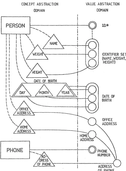
instances that real ~orld concepts may have. Figure 8 shows
the range sets for the attributes of Home-address and Office-address. These attributes describe the entity, Person.
The entity, Phone, has an.attribute, Address-of-Phone, and the range set corresponding to this attribute is also shown. While a range set represents the concept of value abstraction,
the actual values that the database object has at any given
instant is represented by an instance set.
3 .1. 3 Super-range set. There may be situations where a range set encompasses or contains another range set in that
it represents a more general concept than the other. It is sometimes useful to refer to such a set separately as a
super-1•ange set. In Figure 8 the range set for the attribute
Address-of-Phone is shown. For the enterprise (telephone company) this is perceived to encompass the Person's
21,
is thus a super-range set and the conceptual containment of the other two range sets within i t is represented explicjtly
by the solid lines joining the Home-address and Office-address range sets to the Address-of-Phone range set.
3 .1. 4 Token. The instance sets corresponding to each
of the functionally different concept abstractions (that of being described and that of describing) are treated
separately because of the different semantic interpretations. Identical values in instance sets of entities and events
represent the same real world object, while identical values
in instance sets of attributes represent the same description
of different objects. In the instance sets of describable db -objects each unique value represents a unique object in the real world. These values will be called tokens,
In Figure 8 the range sets for the entities Person and Phone are token range sets as each value represents a unique describable object. As events are describable objets, they also have token range sets in the value abstraction domain. Thus, for example, each instance of the events E
1 and E2 in Figure 6 has a corresponding token.
3 .1. 5 Identifiers. Often i t is possible to identify a unique object in terms of its descriptions. For example,
a person may be identified uniquely by the person's name, weight and height if i t is perceived that no two persons have the same values for all of these descriptors. Such a
combination of values of associated attribute instance sets used to identify an entity (or event) is termed an identifie1•.
I
I
I
22.
This is illustrated in Figure 8 where the identifier set {name, weight, height} is considered equivalent to the
token set, I.D.#, and this equivalence is indicated by the dotted line.
It should be noted that the concept of identifiers is different.from that of tokens, since an identifier merely
identifies an object while a token is the object. To illustrate this, consider the example i~ Figure 8 where the entity-type Person, with token range-set I.D.#, has the attribute, Rome-address, and i t is perceived that Home-address is an identifier. Now if the Home-address of a Person with I.D., #x, say, is deleted (representing, for example, that the person has moved but has not yet found
a residence), then although i t is still true that a Home-address, where i t exists, uniquely identifies a Person, it is now not possible to identify Person #x through Home-address, since this Person's Home-address does not exist. The
.existence of the Person in the database is reflected by the token, I.D.#, and not by Home-address. If the actual person leaves the perception of the database, then its token is
deleted together with all its attribute associations. To further illustrate the djfference in concept, i t may be that
at a later time i t is to be perceived that different Persons 1-rnay have the same Home-address. In this case, Home-address
is no longer an identifier of the entity type Person. Since the model should evolve- with·the: perception·· : ·
3,2 The Representation of Dependent Objects
It has been stated that the existence of a describable object is represented by a token and the object may sometimes also be identified by its attributes. A token range set can always he defined for any describable object type (entity or event). Situations arise, however, where the existence of an object is determined by the existence of another.
object.
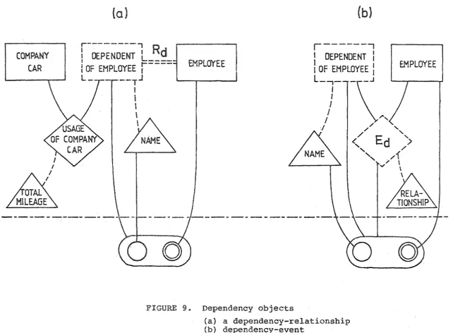
For example, in a corporate database (Figure 9(a)), an entity, Dependent-of-Employee, may be perceived only in the context of the Emvloyee entity on which it is dependent
(Chen [ 6 ]) • Thus the deletion of an Employee from the database requires the deletion of all the Employee's dependents as. well as their attributes. Also, the
identification of a Dependent requires, and is to be only
possible through, the identification of the related Employee. In terms of processing this means that the processing of Dependents is only to be done within the processing of Employees. Figure 9(a) illustrates this situation, where the entity, Dependent-of-Employee, is drawn with dashed lines. This entity has no tokens, as implied by the dependent
i:' identification, since the existence of to~ens allows direct
I
identification of the object. In~tead, the identifier forthis Dependent-of-Employee entity is a concatenation of the tok~n of the entity (Employee) on which i t is dependent
24.
to be uniqu8Jy identified. Figure 9(a) shows the identifier
for the Dependent-of-Employee entity being made up from the
token for the Employee entity and the dependent's Name attribute. The relationship,
Ra,
between the Dependent-of-Employeeentity and Employee entity (through which the former is
dependent on the latter) is called a dependency-relationship. From the above example, a dependent entity can be defined as an entity which does not have a token and its identifier contains a token of the entity on which i t is dependent through a relationship. Note that the owning entity may itself be a dependent entity. In this case the
identifiers of all the nested dependent entities relate to the token of the final owning entity.
A dependency-relationship is the relationship through which one entity is dependent on another. If this
dependency-relationship is itself described, then the
resultant event is a dependency-event. Figure 9(b) shows the event, Ed, obtained when the
dependency-relationship,
Ra,
of Figure 9(a) is perceived as a describable object.A dependent object may also be a component of a regular event. For example, in Figure 9(a) the dependent entity, Dependent-of- Employee, together with the entity, Company-car,
fci:rm the regular event, Us age-of-Company-Cars.
Any db-event that has a dependent object as a member does not have a token. Its identifier consists of the identifier of the dependent object and the tokens of the
25.
of the owning entity (Employee) and the identifier of the dependent entity (Dependent-of-Employee). Since the token
of the owning entity is already part of the identifier of the dependent - entity, the identifier of the dependency-event therefore has the same range set as that of the
dependent-entity (although their instance sets are necessarily different).
3. 3 Data Definition Language
During the logical design of the database, the objects and their associations bave to be defined and declared to
the database management system. These declarations are typically stated using a specified data definition language
(Date [ 10] ) . The decla~ations of the DATAM concepts presented here are straightforward and the construction of an appropriate data definition language presents no difficulty and will not be discussed in detail here. As examples, declarations for the Rbstraction types could be of the following
form:-Entity Person
Event
Token is ID-number
Identified by <Name, Weight, Height>
Attributes are <Rome-address, Office-address, Name, Weight, Height>
Project-Supply Token
Members
is PS-number
are <Froject, Supplier> Attribute is <Part>
RelationshiF Major-Location
The first declaration refers to Figure 8 while the other two are for Figure 2. (The declaration for the
composite-attribute, Date-of-Birth, for Figure 8 is discussed in Section 5.1.5).
It should be noted that the data definition language
27.
4. SUBVIEWS OF THE ABSTRACT MODEL
4.1 Subviews of DATAM modeis
Subviewing is defined as the viewing of a subset of the
modelled world. This facility is important to the enterprise as groups and individuals within i t may want or be allowed to see only a subview of the total view. Whilst the term subview relates to the enterprise view, it should be noted that the terms subschema and submodel (Date [10]), though similar in concept, generally relate more to representational structures.
In the data abstraction model, each construct is based on a well defined associational concept of the real world. Hence, the forming of subviews is determined directly by the meaningfulness of the action on the corresponding concepts
of the real world. Thus well-defined rules can be formulated
for the construction of subviews. The rules for subviewing
in DATAM will be described in this Section. These rules ensure the formation of a subview that represents a valid and consistent perception of a subset of the enterprise view.
4 .1.1 Subviews with Entities. The most basic abstraction is the database entity which represents the existence of an
28.
consisting of any num~er of the db-entities, e.g. Project and City. There is no logical necesiity that these
abstraction types be associated in the subview.
4 .1. 2 Subviews with Attributes. A database
attribute represents a description of a real world object. This means that its existence is meaningful only in
association with the database entity or event which the attribute describes, Also, i t is possible to perceive only some of the descriptions of an entity. Thus, for the DATAM diagram of Figure 2, a valid subview with the attribute
Schedule is one containing this attribute and the entity, Project.
4.1.3 Subviews \'rith Relationships. Database
relationships represent the mutual description between
objects, so that in a model the existence of a relationship is meaningful only in terms of the entities or events
which i t relates. Thus a subview with the relationship R 1 of Figure 2 requires the inclusion of the entities supplier and City.
4.1.4 Subviews with Events. A database event requires
the explicit perception of the objects involved in the association which the event represents as a describable object. Thus a minimum valid subview containing the event E in Figure 2 requires the concurrent perception of the
entities Project and Supplier.
Note that the minimum valid subview containing the relationship R
5 in Figure 6 is the complete diagram itself, as the perception of the relationship R
5 requires the
I I
29.
perception of the events E
30.
5. F.VOLUTION OF THE ABSTRACT MODEL
5.1 Evolution of DATAM models
The construction of an abstract model represents the
perception of the real world at the time of construction. As perceptions of the real world change with time, changes must also be made to the.abstract model to reflect these changes in perception, in order to maintain the usefulness of the database (Swartout et al.
[17],
Navathe and Fry [14], Chen [ 7l ) .
Such changes to the abstract model result ineither an increase or decrease in the number of concepts modelled; and the evolution process is correspondingly defined as progression or regression,
This Section describes the basic operations that are
necessary for the evolution of the abstract model to reflect the perceived changes. The difference in this approach to
some others (see Biller and Neuhold [ 5], Kerschberg et al. [13]) is based primarily on the differences in the abstraction process. In particular; in DATAM, database attributes are viewed as being in the concept abstraction domain and
represent an object-type construct rather than a value range. This emphasizes that attributes are strongly
perceived in the enterprise model instead of the more usual viewing of attributes as mappings from an entity set to a value set. Thus database attributes and entities are seen to be functionally similar in that both have instance sets
which are defined on value ranges, such that an entity-attribute
I
, ..
I 1-'
c
31.
association is represented hy the association of the values
in their respective instance sets.
In this Section, operations for the evolution of DATAM models is discussed. As regression is the inverse of progression, for each sequence of progression operations, there is a sequence of regression operations to reverse the operation·. As such,. the following discussion will be limited to the factors involved in progression operations. Also, the straightforward operations involving the entry and exit of objects from the database, such as the addition of
a new entity type, are nmt considered here. Sections 5.1.l.
to 5.1.4. discuss operations on the transformation of one abstraction type to another while Sections 5.1.5 and 5.1.6
discuss operations defined on the instance sets of abstraction types and introduces the concepts of composite-attribute and sub-object types. The effect of the evolution process on subviews is discussed in Section 5.2.
5.~.l Attribute~Rntity. A db-attribute represents
the description of an entity. If the descriptor (attribute) itself becomes perceived as a db-entity, then the previous entity-attribute association becomes a relationship,
representing the mutual description between the entities.
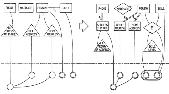
Category-of-Address), the Phone : Address-of-Phone association becomes a relationship, R
2, and the Address-of-Phone value range set becomes a token range set.
Such a change may also force the change of other attributes into entities. This would occur if the attribute being changed represents a description which conceptually encompasses others in the database. This containment is evident in the associations among value ranges {and is shown explicitly in the value abstraction domain of the DATAM diagram). Hence where the value range of the attribute being changed. is a super-range
set, then the contained ranges also become token ranges, which thus changes the attributes defined on them into entities and their associations into relationships. In Figure 10, for example, the change in perception of the attribute Address-of-Phone into an entity forces a change in the other two attributes (Office-address and
Home-address), which are conceptually encompassed by the Address-of-Phone attribute, into entities.
A similar change also occurs when a sub-range set becomes a token set as this implies that its super-range
set has al~o to be a token set. For example, the
32.
33.
5.1.2 Entity+Event. An event (object) of the real world may be Modelled as a db-entity. For example, in Figure 10 the real world perception of a "marriage" event is modelled as a db-entity (Marriage). If the objects involved in the real world event are themselves modelled and their associations with the db-entity which represents the event is to be indicated, then this db-entity
is
changed to a db-event. This progression
is
illustrated in Figure 10 where the couple involved in the marriage is tobe indicated. Note that an instance of the Marriage event involves two separate instances of the Person entity.
5 .1. 3 Relationship-+Event. A database relationship represents the association or mutual description of two db-entities or events. If this relationship is to be viewed as an object or is to be described, then i t is
modelled as an event,: This change is shown in Figure 10
where relationship R
1 becomes event E. This operation
requires the creation of a token range set for the resultant event. As the associated values from the token instance sets of the objects involved in the event are always
identifiers of all instances of the event, a token range
set of the event can therefore be defined as the concatenation of the values of the token range sets of the objects involved. For example, Figure 10 shows the token range set for the
34.
declaration of the token need be made in the data definition
language (see Section 3,3),
A similar change occurs when an entity-attribute
association is to be described. The attribute is first
changed to an entity (Section 5.1.l ) and the resulting
relationship then changed to an event.
The prog,ress.iooof a relationship to a
dependency-event is also similftr and ·i~ discussed in Section 3.2.
5 .1. 4 Dependent Entity+Regular Entity. A dependent
entity is one whose existence and identification is possible
only through its owning entity with respect to a corresponding
relationship. The change of a dependent entity to a
regular one means that the entity is to exist and be
identifiable independently of other objects. This thus
simply involves the creation of a token range set for the
dependent entity and b indicate the corresponding change
of the dependency-relationship to a regular one. For
example, in Figure 9(a),a perceived change of the dependent
entity, Dependent-of-Employee, to a regular one would be
effected by the creation of a token range set for this
entity. The dependency-relationship, Rd' in Figure 9(a)
then becomes a regular relationship.
5.1.5 Composite-attribute. The above Sections
discussed operations on abstraction types. This Section
and the next discusses operations that bear on instance-ba~ea
constructs and thus affect the value associations of the
31·
:::>.
One concept which in principle. is commonly available
is where a descriptor instance of an object is the physical concatenation of other descriptor instances. Consider, for example, the following declarations (in a data definition .language)
Attribute Date-of-Birth
Members are <Day, Month, Year>
Attribute Person-Name
Members are <First-name, Last-name>
where the attribute, Date-of-Birth is seen to consist of the attributes Day,. Mont.h and Year, and the. attributes
First-name and Last-name together constitute Person-Name.
The motivation behind such a decomposition is typically the requirement to be able to refer to, and to manipulate portions of,a descriptor instance independently, as well as to refer to i t as a unit.
The actual operations of the fragmentation and concatenation to represent the above concept are based on the instances
of the attributes. It is the attribute value instances that are composed ordecomposed, with the value range sets serving,
as usual, only to define the scope of the constituent values. To reflect this situation, the oomposite-att~ibute
36.
The operationsnecessary to effect changes to the composite-attribute are operations for the adrlition of attribut~s to and deletion of attributes from a composite-attribute. These operations conceptually include operations for the composition of a composite-attribute from a set of attributes and the corresponding decomposition.
It should be noted that the above definition of the composite-attribute allows for the construction of nested attributes.
5.1.6 Sub-entity and Sub-event Types. Given an entity type, it is possible to derive a subset of its
instance set dynamically, using appropriate access operators. Such a subset can then be used in subsequent p;ocessing.
This conceptual subset of the entity is not,howcver,permanent as i t is not perceived as a separate object-type in the
model, and would therefore not be automatically maintained across sessions. To make the perceived subset of the entity permanent a corresponding entity-type has to be created,
the tokens of which are necessarily contained in the token range set of the source entity-type. The object thus created is a sub-entity-type, For each token of the sub-entity
there is a corresponding token of the source entity such
that they both represent the same real world object~ Thus, any operation on the token of a sub-entity is applicable to
37.
To illustrate this, consider the exampl~ in Figure 11, where Son is a sub-entity of Child and the containment of the Son token range in the Child token range is indicated by the arrow. The perception of a new Son, indicated by the creation of a new unique instance for the Son sub-entity type, would trigger the entering of this new
Son instance into the instance set of the Child entity (if i t is not already there). The rev~rse case,however, is not immediate. To include a new Child instance into the Son instance set requires that the Child be male. This condition, however, cannot be established if sex is not modelled as an attribute of Child. Thus, an external decision is required in such a case.
The instance association between a sub-entity and source-entity types are therefore not symmetric. The
inclusion from sub to source is immediate. The reverse is condi_tional, where the inclusion may be system controlled
if the database models enough concepts .to define the inclusion criteria.
A similar process can be described for the event
abstraction type.
Associated with this concept would be operations for
th~ forming of a sub-object-type from ari existing object-type either with respect to external conditions or system
controlled criteria. The reverse operation forms an object~type which contains objects already existing.
operations of Chen
I
7] for the entity-relationship modeland that of Swartout et al. [17! for network databases).
5.2 Evolution and Subviewing
38.
Since subviews represent consistent subsets of the enterprise view, they can be constructed by the process of regression.
The implementation of a subview has a bearing on the actions required to maintain consistency in the event of an evolution (particularly, a regression) of the enterprise
view. Since a subview is defined with respect to a specific model, its consistency is determined by the state of the
model at the time of.the subview construction. However, subsequent evolutions may affect the consistency of the subview representation as a subset of the model. That
is, the subview may contain associations or objects not now represented by the database.
For example, if the construction of a subview results in a complete sub-database embodying all the object and association types, instances and value range specification,
then any regression of the database would require a· separate parallel action on the subview. On the other hand, if
the subview is implemented such that i t shares the instances of the database, then a change in the instances of the
database in effect also changes the appropriate subview instances.
The choice of the level of definition of subviews is determine~ by the degree of awareness required by the user.
6. ANALYSIS OF DATA MODELS
6.1 DATAM as a Semantic Reference
Since data models are based on representation structures they are subject to interpretation as it is not clear what concepts are represented. In the analysis of data models, an interpretation can be fixed in terms of an
external semantic reference. Abstract models can provide such a reference. In general, an interpretation of a data model imposes a discipline on the construction of its
structures. The use of DATAM in the analysis of data models is presented in this Section ..
3 !) •
As data model structures are representations of instances of associational concepts, correspondence with DATAM is best seen through comparisons with DATAM instance. representations. Section 6.2 describes the representations that will be used.
Analyses of the relational and. network models are presented in Sections 6.3 and 6.4 respectively. These analyses
form the basis for the consideration of correspondence between the models, which i~ described in Section 6.5.
6.2 A Representation of DATAM Instances
A perception of DATAM instances are required in the analyses of data models. In order to relate to the structural
6. 2. 1 EA··tabJ e type. Instances of the associations of an entity to its attributes are representeo hy nn
EA-table (Figure 12(a)). In this table, the first column rEpresents a token instctncE?, set of an entity type and the other columns represent the instance sets of all the
4 0.
attribute types of that entity. Each row of the table indicates
a particular association of the entity instance to its attribute instances. For example, the first row in Figure 12(a)
represents an association of a token t
1 of the entity to particular attribute instances, e.g. v
11 of attribute type
A
1• Row two represents an association of the same token t
1 with another instance, v 12, of the attribute A1•
6.2 .. 2 R-table type. Tables of this type represent relationships. Each table (e.g. Figure 12(b)) consists of two columns containing token instances of the two participating object-types(entities or events).
6.2.3 Ev-table type. These tables represent events. Each table has columns representing the event tokens,
tokens of the member objects,and the attribute instances of the event. These represent the existence of the event,
the embedded relationships among the member objects (see Section 2.2.5), and the descriptions of the event. An Ev-table is illustrated in Figure 12(c).
6.3 Analysis of the Relational Model
41.
normalized relations (Codd [ 9], Bernstein [3]). These
normalized relations have a correspondence wi.th the tables in the DATAM representation of Section 6.2. This fact is used in the analysis of normalized relations where relations structurally similar to one of the DATAM tables are interpreted as representing the same concept as that
of the table.
No direct correspondence however can be made between relational keys and DATAM tokens. The keys in the
relational model uniquely identify tuples (rows of the tables) rather than db-entities. It is thus difficult to base a semantic analysis of a relational model on the
internal structure of its relations as this reveals little of the represented concepts of the real world.
The stateq functional dependencies of a relational
'
model represent the perceived semantic constraints and they completely determine the construction of normalized
relations. An analysis of a relational model can therefore be based on functional dependencies. Nevertheless, because functional dependencies are defined on representational
rather than abstract structures, such interpretation is subject to ambiguity. This ambiguity can be resolved by relating
each distinct dependency type to an abstract concept. The abstract constructs of DATAM can be used for this purpose, and the analysis of a relational model with DATAM is
described here.
4 2.
model is given in Figure 13(a). The set of normalized
relations constructed from these dependencies as given by
Bernstein is shown in Figure 13(b) and the DATAM interpretation of the model is presented in Figure 14.
6.3.l Descriptor types. As stated, an analysis of a relational model here is based upon its dependencies.
Consider the dependency, T: Stock#+ Price, of Figure 13(a). The dependency represents the instance associations of Stock# and its Price. Here Price can be viewed as a descriptor of Stock#, that is, the Right Hand Side (RHS) of this
dependency is a desc+iptor of the object on the Left Hand Side (LHS). This corresponds to a db-entity:db-attribute. association so that the dependency T can be interpreted as the DATAM substructure Td in Figure 14. Td represents the Stock n: 1 Price association where the entity Stock has Stock# as a token. The relational dependency Wis
similarly interpreted as the DATAM substructure Wd.
Although the RHS of a dependency, (such as Tor W), is typically the descriptor of the LHS, this situation· is not always so. For example, if the instance association for Stock#:Price is 1:n (instead of n:1) 1 then T I representing this dependency would be expressed as T~:Price + Stock#,
where the descriptor (Price) is now on the LHS. To keep
the descriptor on the RHS, a notational change for T'' to
Ti:Stock# + Price could be made. This suggests a worthwhile
notational rule for dependencies where the de~criptor types are clearly identifiablew In the interpretation of Figure
4 3.
6.3.2 Entity 'J'ype. In DATAM, a descriptor which
is itself described is a db-entity. In the consideration
of the dependenc:iesU and W of Figure 13(a), City is a descriptor of Dept (from dependency U) and is itself
described by Population (dependency W). Therefore City is to be viewed as a db-entity. Thus the Dept:City association is one between two entities, and is the
db-relationship shown in the DATAM substructure, Ud' in Figure 14.
6.3.3 Event Type. Situations occur where either side of a dependency.consists of more than one object
(relational attribute). This combination represents an association among the constituent objects and is interpreted as a db-event. For example, the dependency S has the
combination {Stock#,Dept#} which is interpreted as the db-event, Stock-in-Dept, involving the entities, Stock and Dept. The dependency S therefore represents the description of the event by the db-attribute, Quantity and is shown as
substructure sd in Figure 14.
6.3.4 Multivalued dependency. From the above analysis, functional dependencies are seen to represent association
between object~ and their descriptorD. The definition of
functional dependency (Codd [9]) allows only an n:1 association. The inadequacy of this n:1 associational restriction has
recently motivated the introduction of the generalized
multivalued dependency, where m:n associations can be
4 4 •
dependencies, each DATAM association (m:n or n:1) follows that of the dependency.
6.4 Analysis of the Network Model
The network model has two basic structures - record type· and set type. Network struct~res are generally represented by data structure diagrams (Bachman [2] ).
6. 4 .1 Entity-attribute associations. A record type
is used to represent the existence and deacription of a real world entity (Taylor and Frank [18]), so that, in value instances, i t corresponds to the DATAM EA-table of
Section 6.2. The keyfi.eld of this record type corresponds to the token column of the EA-table and non-key fields
correspond to attribute columns. Thus a record type can be interpreted as entity-attribute associations where a repeating group is viewed as an n:m entity-attribute instance association and a field within the record type
is view, ed as an n: 1 association.
Figure 15(a) shows a network model. The non-key fields for each of the record types are also indicated in the
Figure. Record types are interpreted a$ db-entjty: db-attribute association, so that th~ record type City corresponds to the DATAM substructure Wd in Figure 14. Similarly record type Stock corresponds to the DATAM
substructure, Td.
6. 4. 2 Relationship type. A set type represents the
1:n association of record occurences of a record type
to those of another. In value instances,therefore, a set
I.
type corresponds to the DATAM R-table with an imposed
1:n association restriction.
The set type, LOCATION, in the substructure U in n Figure 15(a) represents the 1:n association of City occurrences to Dept occurrences. This is interpreted as the db-relationship between the db-entities City and Dept in Figure 14.
6.4.3 Event type. Consider the substructure, S •
- n
Network structures of this form are ambiguous as they are 4 5 ,
used to represent two distinct concepts (Taylor and Frank (18] l.
In one case, the record type Stock-Dept-Link is seen as a db-entity so that the set types Held-in-Dept and Stock-Held are seen as two distinct db-relationshi~s involving this
entity.
On the other hand, the record type, Stock-Dept-Link, can be seen to facilitate a many-to-many association of the record types, Stock and Dept. In this case, the
substructure, S , is interpreted as the DATAM substructure, n
Sa,
containing a db-event.To resolve the above ambiguity, in the analysis of a
network model, the interpretation of network structures of the form of Sn has to be fixed, (see also Chen
[i}).
One method is to adopt the second approach discussed above. This involves the interpretation of record types that are
owned as forming db-events. With this approach,however,
overcome this, the association between Dept and City has to be represented through the substructure, Xn' shown in
Figure 15(b) where a dummy record type is introduced to
4 6.
facilitate the association. With this change, the relation-ship between the entities, Dept and City becomes emb~dded in
the db-event, Dept-City-Link. Therefore, in this method, there is no network structure than can be directly i~terpreted as a db-relationship.
6.5 Correspondence of Data Models
The transformation of a data model to another hased on their structural constructs ' j s semantically intuitive (Biller and
Neuhold [4]) and therefore provides no guarantee of the validity of the correspondence where the interpretation of particular structures may be ambiguous. To ensure a valid correspondence, a semantic reference is used to impose an interpretation on the models with respect to which the
correspondence is to be defined. for such an interpretation.
DATAM provides a basis.
This Section discusses the correspondence between the
network and relational models in terms of the DATAM interpretations
presented in Sections 6.3 and 6.4. In the interpretation of the network model presented in Section 6.4, a discipline was imposed where dummy record types are introduced in order
to preserve the entity role of some record types. A
consequence of this is that db-relationships have no distinct