ORIGINAL RESEARCH
INTERVENTIONAL
Enhanced Aneurysmal Flow Diversion Using a Dynamic
Push-Pull Technique: An Experimental and Modeling Study
D. Ma, J. Xiang, H. Choi, T.M. Dumont, S.K. Natarajan, A.H. Siddiqui, and H. Meng
ABSTRACT
BACKGROUND AND PURPOSE: Neurovascular flow diverters are flexible, braided stent-meshes for intracranial aneurysm treatment. We applied the dynamic push-pull technique to manipulate the flow-diverter mesh density at the aneurysm orifice to maximize flow diversion. This study investigated the hemodynamic impact of the dynamic push-pull technique on patient-specific aneurysms by using the devel-oped high-fidelity virtual-stenting computational modeling technique combined with computational fluid dynamics.
MATERIALS AND METHODS: We deployed 2 Pipeline Embolization Devices into 2 identical sidewall anterior cerebral artery aneurysm phantoms by using the dynamic push-pull technique with different delivery-wire advancements. We then numerically simulated these deployment processes and validated the simulated mesh geometry.Computational fluid dynamics analysis was performed to evaluate detailed hemodynamic changes by deployed flow diverters in the sidewall aneurysm and a fusiform basilar trunk aneurysm (deployments implemented previously). Images of manipulated flow diverter mesh from sample clinical cases were also evaluated.
RESULTS:The flow diverters deployed in silico accurately replicated in vitro geometries. Increased delivery wire advancement (21 versus 11 mm) by using a dynamic push-pull technique produced a higher mesh compaction at the aneurysm orifice (50% metal coverage versus 36%), which led to more effective aneurysmal inflow reduction (62% versus 50% in the sidewall aneurysm; 57% versus 36% in the fusiform aneurysm). The dynamic push-pull technique also caused relatively lower metal coverage along the parent vessel due to elongation of the flow diverter. High and low mesh compactions were also achieved for 2 real patients by using the dynamic push-pull technique.
CONCLUSIONS: The described dynamic push-pull technique increases metal coverage of pure braided flow diverters over the aneurysm orifice, thereby enhancing the intended flow diversion, while reducing metal coverage along the parent vessel to prevent flow reduction in nearby perforators.
ABBREVIATIONS:DPPT⫽dynamic push-pull technique; FD⫽flow diverter; PED⫽Pipeline Embolization Device
U
sed for intracranial aneurysm treatment, a neurovascular flow diverter (FD) is a braided stent-mesh device highly flex-ible in stretch and compression. A bench top study showed that an FD can form varied mesh densities through longitudinal compres-sion,1consistent with our recent findings.2Meanwhile, there arecon-cerns with using FDs in perforator-rich territories due to the likely
occlusion of small vessel ostia. While increased mesh density at the aneurysm orifice may help aneurysmal flow reduction, it would be beneficial for the mesh density to be reducible in perforator-rich re-gions to preserve the perforators and branch vessels.
We used the dynamic push-pull technique (DPPT) to effec-tively control the local FD mesh density. The concept of dynamic push-pull was originally introduced to keep the laser-cut stent at vessel centerline during its deployment.3It was later extensively
used in FD deployment to achieve complete opening and good wall apposition at highly curved locations.4,5Here, we further
extended the technique, targeting flow control with the following objectives: 1) to adjust for the distal foreshortening of the FD, 2) to optimize the mesh density across the aneurysm neck to increase flow diversion, and 3) to decrease the mesh density to avoid oc-clusion of perforator ostia and branch vessels. The deployment technique involves individually varying the push and pull of the microcatheter and the delivery wire to control the FD mesh den-sity and the positioning.
Received September 26, 2013; accepted after revision January 30, 2014.
From the Toshiba Stroke and Vascular Research Center (D.M., J.X., A.H.S., H.M.) and Departments of Mechanical and Aerospace Engineering (D.M., J.X., H.M.), Neurosur-gery (J.X., S.K.N., A.H.S., H.M.), and Radiology (A.H.S.), University at Buffalo, The State University of New York, Buffalo, New York; Department of Neurosurgery (H.C.), Upstate Medical University, The State University of New York, Syracuse, New York; and Department of Surgery (T.M.D.), The University of Arizona; Tucson, Arizona.
Please address correspondence to Hui Meng, PhD, Toshiba Stroke and Vascular Research Center, University at Buffalo, The State University of New York, 875 Ellicott St, Buffalo, NY 14203; e-mail: [email protected]
Indicates article with supplemental on-line figures.
To examine the DPPT in detail, we used in vitro testing and numerical modeling. Due to the limited resolution of current clinical angiography, it is still difficult to visualize and characterize the real-time FD deployment in patients. However, simulations of FD deployment and aneurysmal hemodynamics allow us to visu-alize, verify, and better understand the DPPT operation, which re-presents a significant advancement in intracranial aneurysm intervention.
We have recently developed a finite-element-analysis work-flow,6 referred to as the high-fidelity virtual stent-placement
method. A follow-up study validated it through FD deployment in a fusiform phantom,2where DPPT was used on 2 FDs in 2
identical fusiform (basilar artery) aneurysm phantoms for differ-ential mesh densities. We did not verify the posttreatment hemo-dynamic changes and did not investigate sidewall aneurysm mor-phology. In the current study, we further applied DPPT for the sidewall anterior cerebral artery aneurysm both experimentally and numerically. Computational fluid dynamics analyses were then performed in all 4 flow-diversion scenarios, including the sidewall and the previously deployed fusiform morphologies to evaluate the hemodynamic impact of DDPT on intra-aneurysmal flow.
MATERIALS AND METHODS
Aneurysm Models: Numerical and In Vitro
One wide-neck anterior cerebral artery saccular aneurysm (dome⫻neck: 15⫻7 mm) was used as the sidewall aneurysm geometry for our testing. Its maximal parent vessel size was 3 mm. This geometry was chosen because preliminary computational fluid dynamics showed a strong inflow jet impinging on the distal fundus due to vessel curvature; flow diversion could help reduce the impinging flow. The numerical aneurysm model was created from 3D image segmentation. Two polymer phantoms of the an-eurysm were created by using the previous method.2The
phan-tom was connected to a flow loop to reduce friction. Microscopic images from the lateral and base (facing the aneurysm neck from the parent vessel) views were obtained during and after FD im-plantation for mesh analysis. Another model—a fusiform basilar trunk aneurysm—was created previously.2
Flow Diverter
The Pipeline Embolization Device (PED; Covidien, Irvine, Cali-fornia) was used in the current study. It consists of a 48-strand braided FD mounted on a delivery wire (On-line Fig 1). The distal capture coil and the pusher are soldered on the wire at the distal and proximal ends of the FD, respectively. The FD and wire are placed in a microcatheter (inner diameter⫽0.027 inch/0.686 mm).
Dynamic Push-Pull Technique
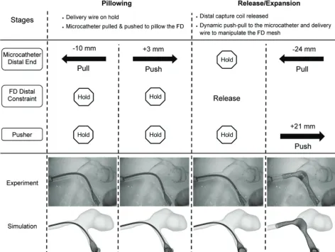
Because the deployed FD geometry mainly depends on the releas-ing process, our deployment analysis focuses on operations after the delivery system placement over the aneurysm orifice. Dy-namic push-pull manipulation is used in 2 phases: pillowing and release/expansion.
Pillowing. The microcatheter is first retracted while the delivery wire is secured without translation (so is the FD attached to the
delivery wire) to allow the FD to be expressed from the distal tip of the microcatheter. Then the microcatheter is pushed with the de-livery wire still secured, forcing the FD to radially dilate and con-form to the vessel wall. This operation aims to generate sufficient FD-vessel apposition to minimize the distal foreshortening.
Release/Expansion. The pillowed FD is released from the capture coil by rotating the delivery wire clockwise while maintaining the positions of the wire and the microcatheter. Two basic maneuvers may be followed through the rest of the deployment: 1) withdraw-ing the microcatheter while holdwithdraw-ing the wire, in effect of un-sheathing the FD; and 2) pushing the delivery wire to unsheath and compact the FD. These 2 maneuvers are frequently combined to achieve optimal deployment. The FD is completely released at the end.
Sometimes pushing the delivery wire alone may not be suffi-cient to overcome the resistance of the FD. The temporary push-back of the microcatheter together with the delivery wire may be necessary for robust compaction.5 However, for a controlled
study, here we only allowed the microcatheter to be continuously retracted and the delivery wire to be continuously advanced (with varied advancement values), to evaluate the wire advancement alone and to simplify simulations.
Numerical Modeling of FD Deployment
We used our previously described, finite-element-analysis–based high-fidelity virtual-stenting technique2,6to recapitulate the
de-tailed deployment process in silico to study FD flow modification by computational fluid dynamics. The high-fidelity virtual stent-ing workflow incorporated several simplifications: 1) The delivery wire functionality was provided by the distal capture coil (before releasing the distal end of the FD) and the pusher (after the distal release); 2) a pathway was specified to guide the distal capture coil, the microcatheter, and the pusher; and 3) the vascular wall was assumed rigid in FD-vessel interaction. The virtual FD model in the stress-free state was constructed to simulate procedures of crimping, delivery, and expansion.
Analysis of Deployed FD
To quantify the FD mesh geometry after deployment, we used “metal coverage,” defined as the total outer surface area of the FD strands divided by the area of the tubular surface framed by the FD, and “pore density,” defined as the number of pores per unit area of the tubular surface framed by the FD.7Detailed calculation
of these parameters was introduced elsewhere.2Following
Ma-koyeva et al,1we divided the FD mesh near the aneurysm orifice
into 5 segments for mesh analysis: proximal vessel, proximal tran-sition, middle, distal trantran-sition, and distal vessel.
Hemodynamic Analysis
Newtonian flow with rigid-wall conditions. The density and vis-cosity of blood flow were 1056 kg/m3and 3.5 cP, respectively. A
typical Reynolds number of 362 was applied to all simulations as the inlet boundary condition. Flow patterns were visualized by streamlines; inflow reduction was calculated as the difference be-tween pre- and posttreatment aneurysmal inflow rates normal-ized by the pretreatment inflow rate.
Clinical Case Examination
To evaluate the potential effectiveness of DPPT in flow diversion, 2 clinical FD cases, one with high mesh compaction and the other with low mesh compaction, were selected from our hospital. By assuming that the gray-scale intensity of the image is proportional to real mesh density, we analyzed the average metal coverage along the FD by using the method above.
RESULTS
In Vitro and Numerical FD Deployment in the Sidewall Aneurysm
In each of the sidewall phantoms, we deployed a PED by using DPPT. Distal foreshortening of the FD was largely overcome by the pillowing procedure. One PED (labeled 3.5⫻20 mm) was deployed with greater delivery wire advancement (21 mm) than the other PED (labeled 3⫻25 mm, wire advanced 11 mm) during
the release/expansion stage, resulting in higher mesh compaction over the aneurysm neck region. These 2 scenarios are referred to as high- and low-compaction, respectively. Numerical simula-tions recapitulated the in vitro DPPT processes. Figure 1 shows stepwise deployment in vitro and in silico.
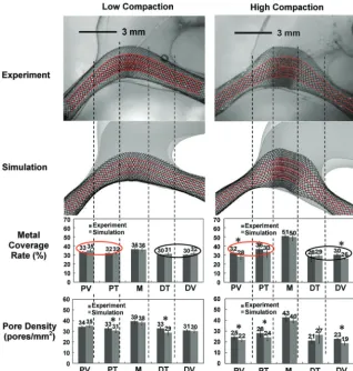
Deployed Mesh Geometry: Comparison of In Vitro and Numerical Results
High correlation was achieved between experimental and numer-ical results of FD deployment. Figure 2 shows mesh geometry and mesh density quantification in the lateral view (the base view is given in On-line Fig 2). Greater delivery wire advancement (21 mm) generated higher compaction at the orifice (50% metal cov-erage, 40 pores/mm2pore density) compared with that with less
wire advancement (11 mm, 36% metal coverage, 38 pores/mm2
pore density). Mesh densities at parent vessels and transition zones (30% metal coverage) were similar between high- and low-compaction scenarios and were lower than that in the neck region of the high-compaction case. The nonparametric test confirmed the excellent accuracy of the simulation.
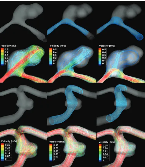
Hemodynamic Evaluation of Flow Diversion
In streamline plots in Fig 3, all 4 FD-treated scenarios showed pronounced reductions of aneurysmal velocity and inflow
[image:3.594.58.531.53.408.2]pared with untreated scenarios. High-compaction mesh diverted more flow than the low-compaction mesh (inflow reduction: 62% versus 50% for sidewall, 57% versus 36% for fusiform). The high-compaction mesh for the sidewall aneurysm attenuated the iner-tia-driven inflow jet and redirected it to the more proximal region (Fig 3), which potentially alleviates negative impacts of the flow impingement.
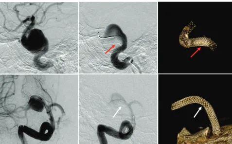
Mesh Analysis of Clinical Cases
Figure 4 shows 2 clinical PED cases. The case on top was treated by a PED deployed with high compaction, giving improved FD-vessel apposition. Metal coverage near the orifice (inflow zone) and the distal vessel was estimated as 46% and 18%, respec-tively. In the second illustrated case, the FD was stretched across the orifice (18%) with normal coverage at the parent vessels (24%–30%).
DISCUSSION
The current study found the following with DPPT: 1) The distal foreshortening of the FD was prevented by the pillowing tech-nique; 2) higher FD metal coverage across the aneurysm orifice could be achieved by greater delivery wire advancement; 3) lower
metal coverage at perforator regions could be achieved by smaller wire ad-vancement and greater withdrawal of the microcatheter; and 4) high-compaction mesh resulted in greater inflow reduction (than low-compaction), which theoreti-cally promotes aneurysm occlusion.
The FD foreshortening has been fre-quently encountered in practice.4,5
Fore-shortening occurs once the FD is released from the crimped state. The released FD radially expands and longitudinally fore-shortens; this change makes the optimal placement of the FD relatively unpredict-able, especially for a poorly sized FD. As a countermeasure, the pillowing technique was effective in preventing distal migra-tion of the FD as it foreshortened.
To actively control the FD mesh, we demonstrated that the additional deliv-ery wire/pusher advancement (approxi-mately 10 mm) was sufficient to generate high-compaction mesh (metal coverage: 50% versus 36%). Similar results were found for the fusiform aneurysm in the previous study (metal coverage: 49% ver-sus 40%, by a 6-mm difference in wire ad-vancements).2In practice,
high-compac-tion mesh can be achieved by pushing the delivery wire, either alone or together with the microcatheter, to radially expand and longitudinally compress the FD. However, when the FD is over important arterial branch ostia (eg, the anterior cho-roidal or posterior communicating arter-ies), we suggest additional pull of the mi-crocatheter while holding the delivery wire to generate low-compaction mesh for the patency of small vessels.
Our experience shows that the above operations would work better around the orifice than inside parent vessels, because once a given FD fully expands to the vessel, its metal coverage is mainly determined by the vessel size and DPPT becomes less effective. This characteristic was confirmed by our result that mesh densi-ties from the high- and low-compaction scenarios were similar in corresponding parent vessels (Fig 2).
One should also be mindful of potential risks of dense com-paction: 1) Denser mesh increases the chance of occluding perfo-rators and side branches, given that these vessels can only tolerate up to 50% ostial coverage as previously suggested8; 2) forceful
pushing can lead to flattening, torsion, and even intussusceptions of the FD,9compromising the vessel lumen with potentially
dev-astating consequences; 3) controlled, selectively increased metal coverage over the aneurysm neck may take time to master and is more difficult to perform in tortuous vascular anatomies.
Flow simulations showed that high-compaction mesh was more effective (additional 12%–21% reduction) in diverting aneurysmal inflow than low-compaction mesh. Most interest-ing, the flow reduction by the high-compaction mesh of the
[image:4.594.53.372.47.381.2]sidewall aneurysm in the current study (62% inflow reduction) is comparable with the performance of overlapping 2 FDs (69% reduction of mean aneurysmal velocity) reported by Augsburger et al.10 However, further analysis is needed to
verify this observation. With regard to the clinical implications of flow reduction, it is understood that more flow reduction leads to more immediate and complete thrombotic occlusion, therefore avoiding the complications related to aneurysm rupture.11,12
The orifice coverage of the first clinical case matched the cur-rent high-compaction mesh of the sidewall aneurysm (46% versus 50%), indicating comparable flow reduction. The low-compac-tion mesh of the other case was favorable for branch vessel pres-ervation, but with compromised flow reduction. These 2 cases showed high variability of the FD mesh and potentially distinct flow modifications under the DPPT operation.
Limitations of the current study include the following: 1) Only the hemodynamics of 2 aneurysm geometries were analyzed.
[image:5.594.58.535.46.591.2]However, these 2 were typical cases suitable for flow diversion (wide necks and complex geometries less optimal for coiling or clip-ping); 2) the 3.5⫻20 mm FD for high-compaction was oversized (3.5 versus 3 mm) due to limited FD sample availability. Oversized FDs were reported to achieve less flow reduction than nonoversized ones,13indicating an underestimation to the flow reduction of the
current high-compaction scenario; and 3) rigid wall was assumed through the deployment. Future direction would be to further exam-ine the effects of DPPT on aneurysm occlusion and perforator pres-ervation in clinical cases following flow diversion.
CONCLUSIONS
The current study investigated the variability of the pure braided FD mesh deployed by the DPPT in patient-specific aneurysm models and evaluated the consequent flow-diversion perfor-mance. The selective use of DPPT during FD deployment gener-ated enhanced aneurysm flow reduction by creating high mesh compaction over the aneurysm neck. DPPT was also capable of maintaining relatively low compaction over perforators/branch vessels to aid their preservation.
Disclosures: Adnan H. Siddiqui—UNRELATED:Board Membership: Codman & Shurtleff, Covidien Neurovascular,Consultancy: Codman & Shurtleff, Concentric Medical, Covidien Vascular Therapies, Guidepoint Global Consulting, Penumbra, Stryker Neurovascular, Pulsar Vascular, MicroVention,Grants/Grants Pending: Na-tional Institutes of Health,* University at Buffalo,*Comments: National Institutes of Health (coinvestigator: National Institute of Neurological Disorders and Stroke, 1R01NS064592-01A1, “Hemodynamic Induction of Pathologic Remodeling Leading to Intracranial Aneurysms”); University at Buffalo (Research Development Award), Na-tional Institutes of Health (coinvestigator: NaNa-tional Institutes of Natural Sciences, 5 R01 EB002873-07, “Micro-Radiographic Image for Neurovascular Interventions”),
Payment for Lectures (including service on Speakers Bureaus): Codman & Shurtleff,
Stock/Stock Options: Hotspur, Intratech Medical, StimSox, Valor Medical, Blockade Medical,Other: Abbott Vascular, AANS (American Association of Neurological Sur-geons) Courses, Penumbra,Comments: honoraria. Hui Meng—UNRELATED:Grants/ Grants Pending: National Institutes of Health R01 research grant,* Covidien,* Toshiba,* *Money paid to the institution.
REFERENCES
1. Makoyeva A, Bing F, Darsaut TE, et al.The varying porosity of braided self-expanding stents and flow diverters: an experimental study.AJNR Am J Neuroradiol2013;34:596 – 602
2. Ma D, Dumont TM, Kosukegawa H, et al.High fidelity virtual stent-ing (HiFiVS) for intracranial aneurysm flow diversion: in vitro and in silico.Ann Biomed Eng2013;41:2143–56
3. Heller RS, Malek AM.Delivery technique plays an important role in determining vessel wall apposition of the Enterprise self-expand-ing intracranial stent.J Neurointerv Surg2011;3:340 – 43
4. Lubicz B, Collignon L, Raphaeli G, et al.Pipeline flow-diverter stent for endovascular treatment of intracranial aneurysms: preliminary expe-rience in 20 patients with 27 aneurysms. World Neurosurg
2011;76:114 –19
5. Fischer S, Vajda Z, Aguilar Perez M, et al.Pipeline embolization device (PED) for neurovascular reconstruction: initial experience in the treatment of 101 intracranial aneurysms and dissections.
Neuroradiology2012;54:369 – 82
6. Ma D, Dargush GF, Natarajan SK, et al.Computer modeling of deploy-ment and mechanical expansion of neurovascular flow diverter in pa-tient-specific intracranial aneurysms.J Biomech2012;45:2256 – 63 7. Lieber BB, Sadasivan C.Endoluminal scaffolds for vascular
recon-struction and exclusion of aneurysms from the cerebral circulation.
Stroke2010;41:S21–25
[image:6.594.55.533.45.341.2]definitive endovascular therapy for intracranial aneurysms.J Neu-rointerv Surg2009;1:56 – 65
9. Dumont TM, Mokin M, Snyder KV, et al.A paradigm-shifting tech-nology for the treatment of cerebral aneurysms: the Pipeline embo-lization device.World Neurosurg2013;80:800 – 03
10. Augsburger L, Farhat M, Reymond P, et al.Effect of flow diverter porosity on intraaneurysmal blood flow. Clin Neuroradiol
2009;19:204 –14
11. Kulcsa´r Z, Houdart E, Bonafe A, et al.Intra-aneurysmal thrombosis as a possible cause of delayed aneurysm rupture after flow-diver-sion treatment.AJNR Am J Neuroradiol2011;32:20 –25
12. D’Urso PI, Lanzino G, Cloft HJ, et al.Flow diversion for intracranial aneurysms: a review.Stroke2011;42:2363– 68