MASTER THESIS
DESIGN OF A
STATICALLY BALANCED
FULLY COMPLIANT
GRASPER
USING THE RIGID BODY
REPLACEMENT METHOD
A.J. Lamers
FACULTY OF ENGINEERING TECHNOLOGY MECHANICAL ENGINEERING
MECHANICAL AUTOMATION AND MECHATRONICS
EXAMINATION COMMITTEE
prof. dr. ir. J.L. Herder (chairman)
J.A. Gallego Sanchez Msc
ir. K.P.G. Folkersma
prof. dr. ir. A. de Boer
DOCUMENT NUMBER -
preface
Sinds 42 het antwoord is op de ultieme vraag over het leven, het universum, en alles1, kan men zich afvragen of
het beter is om antwoorden te hebben of vragen. Of (geen van) beide. De vragen houden je bezig. De antwoorden maken het dagelijks leven gemakkelijker, en geven voor korte duur rust. Ze blijken opgebouwd te zijn uit tig
nieuwe vragen. In dit werk komt ten minste 1 antwoord voor. Een robuust stuk metaal dat meegeeft bij de kleinste aanraking. Genoeg reden voor genoeg nieuwe vragen.
Ik wil graag het IMR lab op de TU Delft bedanken voor de aandacht, tijd en ruimte die ik gekregen heb om te ontdekken en te leren. In het bijzonder Just Herder en Juan Gallego. Ook bedank ik Gerard Dunning, Sergio Pellegrini, Pieter Pluimers, Jos Lassooij, Nima Tolou, Lodewijk Kluit en Johan Rob, het was erg leuk en leerzaam
om met jullie te werken en op te trekken.
Enschede was onmisbaar. Met regelmaat reisde ik af naar Twente en kon altijd rekenen op een gezellig weerzien
en vanzelfsprekende gastvrijheid. Dat is mij veel waard. Mooi!
Dank,
Toon Lamers
Since 42 is the answer to the ultimate question of life, the universe and evertything 2 one could wonder if it is beter to have questions or answers. Or (neither of) both. The questions leave you occupied. The answers make daily life more comfortable, and give rest for the shoft term. They appear to be composed out of many new
ques-tions. In this work at least one answer can be found. A robust piece of metal that moves along with the slightest touch. Consequently enough new questions may be posed.
I want to thank the IMR lab at the TU Delft for the attention, time and facilities I received in order to explore and learn. Special thanks to Just Herder and Juan Gallego. Also thanks to Gerard Dunning, Sergio Pellegrini,
Pieter Pluimers, Jos Lassooij, Nima Tolou, Lodewijk Kluit en Johan Rob, it was a pleasure to work and meet with you.
Enschede was essential. Frequently I traveled to Twente and always encountered a hospitable and joyful
envi-ronment. That is worth a lot to me. Great!
Thanks,
Toon Lamers
1het boek ”Het Transgalactisch Liftershandboek” door Douglas Adams 2the book ”The Hitchhiker’s Guide to the Galaxy” by Douglas Adams
Abstract
Monolithic and thus fully compliant surgical graspers are promising when they provide equal or better force
feed-back then conventional graspers. In this work a fully compliant grasper is designed to have zero stiffness and the capability to obtain zero operation force. The design problem is addressed by taking a building block approach,
in which a pre-existing positive stiffness compliant grasper is compensated by a negative stiffness balancer. The design of the balancer is conceived from a 4-bar linkage and explores the Rigid-Body-Replacement method as a
novel design approach towards static balancing. Design variables and sensitivities are determined through the use of a pseudo rigid body model. Final dimensions are obtained using rough hand calculations. Justification of the pseudo rigid body model as well as the set of final dimensions is done by non linear finite element analysis.
Exper-imental validation is done through a titanium prototype of 40 [mm] size having an unbalanced positive stiffness of 62.3 [N/mm] showing that a force reduction of 98.92 [%] is achievable over a range of 0.6 [mm]. While hysteresis
is approximately 1.32 [%]. The behavior can be tuned from monostable to bistable. The Rigid-Body-Replacement method was proved successful in the design of a statically balanced fully compliant grasper, widening the design possibilities for this kind of mechanisms.
Contents
preface i
Abstract iii
1 Introduction 1
1.1 Background . . . 1
1.2 Problem statement . . . 1
1.3 Literature review . . . 1
1.4 Objective . . . 2
1.5 Structure . . . 2
2 Method 3 2.1 Criteria . . . 3
2.2 Design . . . 4
2.2.1 building block approach . . . 4
2.2.2 negative stiffness . . . 5
2.2.3 rigid body replacement method . . . 5
2.2.4 topology . . . 6
2.2.5 design variables . . . 6
2.2.6 monolithic design . . . 9
2.2.7 dimensions . . . 10
2.3 Evaluation . . . 12
2.3.1 Obtained design . . . 12
2.3.2 Experiment . . . 12
2.3.3 Design approach . . . 13
3 Results 15 3.1 Model predictions . . . 15
3.2 Measurement of the prototype . . . 15
3.3 Model validation . . . 16
3.3.1 Comparison between the measurement data and the model predictions . . . 16
3.3.2 Sensitivity analysis . . . 17
3.3.3 FE strain energy analysis . . . 17
3.3.4 Linear pre-buckling analysis . . . 18
3.3.5 Numerical scheme for RBM simulation . . . 18
vi CONTENTS
4 Conclusion 23
5 Discussion 25
5.1 The design . . . 25
5.2 The method . . . 26
Bibliography 29
A Review of design approaches for statically balanced compliant mechanisms 31
B Non linear FEM analysis of balancer and grasper 33
C Stress stiffening effect of a clamped beam 35
D Analytical solution of crank slider mechanism 37
E Numerical scheme for crank slider mechanism and GUI 39
F Behavioral study of crank slider mechanism 41
G Effects of mirroring 43
H Linear pre-buckling analysis 45
I Non linear FEM analysis of strain energy 47
J Pseudo rigid body model of crank slider mechanism 49
K Sensitivity analysis of FE model and PRB model 51
Chapter 1
Introduction
1.1
Background
In this work the application of statically balanced fully compliant (SBFC) mechanisms is proved valuable in the
development of a grasper for minimal invasive surgery. Statically balanced compliant mechanisms are mechanisms which achieve motion due to elastic deformation of slender parts, but without requiring any external work. The elastic potential remains constant through the range of motion. Important design requirements for surgical tools
are high force feedback and high sterilisability. Ideally this means removing all hinges which are present in conventional tools used today. This can be done by designing a fully compliant grasper. But then elasticity
will disturb force feedback instead. Here a statically balanced fully compliant mechanism would meet all design requirements. And besides that the monolithic character of statically balanced fully compliant mechanisms also creates opportunities for the design of a inexpensive single piece disposable tool.
1.2
Problem statement
Design of compliant mechanisms is not an easy task. As expressed by Howell [6], the design of compliant
mech-anisms considering only kinematic requirements is challenging enough. Adding the static balancing requirement will in general add even more complexity to the design of the compliant mechanism. The problem is that for this
new class of mechanisms no established general design method exists yet [3]. And known so far no successful prototype has been presented yet of a statically balanced fully compliant surgical grasper [11].
1.3
Literature review
In 1997 the urge for high force feedback was recognized and aimed for by designing a rolling contact mechanism replacing the conventional hinged surgical grasper by Herder et al [7]. In 2000 it was realized by van den Berg and
Herder [4] that friction, wearing, lubrication, etc. could be eliminated by moving towards a zero stiffness compliant design, with the added benefits of sterilizability and reduced assembly costs. While a prototype was made, it was
not a fully compliant design, it consisted of a positive stiffness compliant gripper compensated by a rolling contact mechanism. The balancing mechanism compensates for the elastic forces of the compliant grasper. Later in 2004
Stapel and Herder [10] proposed a feasible solution for a fully compliant version but no prototype was made. De Lange et al. [9] proposed in 2008 a design based on topology optimization, without a proving prototype. In 2009 Tolou and Herder [11] developed a mathematical model for partially compliant bistable segments in order to
2 CHAPTER 1. INTRODUCTION
facilitate the design of a partially compliant balancing mechanism. In 2010 fully compliant balancing segments (negative stiffness building blocks) are introduced by Hoetmer et al [5]. A prototype was created using these segments but exceeded the yield stress due to the pre-loading force.
In literature devoted to the development of this SBFC surgical grasper attention is payed to the design method-ology aswell as the specific design problem itself. Known so far, the proposed and developed methodologies did
not deliver a real world solution for the SBFC surgical grasper. In general not much design examples of SBFC mechanisms are described in literature, the design methodology seems to be undeveloped. See appendix A for a literature review. Allthough there is a vast amount of literature on designing compliant mechanisms [2], the field
of designing SBFC mechanisms seems relatively unexplored [3].
1.4
Objective
The objective of this work is the design and prototyping of a statically balanced fully compliant grasper. The design approach is based on the exploration of the Rigid-Body-Replacement method (RBR) as a novel way to
design statically balanced compliant mechanisms.
1.5
Structure
This work is structured as follows. The method chapter begins treating the design criteria, followed by a chrono-logical description of the taken design steps and concluding with the method of evaluation. The evaluation method
focuses on the obtained design itself using FE analysis, the experimental setup and the taken design approach (RBR method). The results chapter presents the FE predictions for the final design, the measurement results and a validation of the derived pseudo rigid body model used in the rigid body replacement method. In the conclusion
Chapter 2
Method
2.1
Criteria
A grasper for minimally invasive surgery should achieve high force feedback and high sterilizability, staying within
a certain size and weight allowing for easy manual operation and handling. The sterilizability requirement can be met by choosing for a monolithic and thus fully compliant mechanism. High force feedback can be obtained by implying static balance. The size requirement can be accomplished by looking for the smallest allowable
monolithic geometry satisfying a certain balance quality. It is assumed that meeting the size requirement means meeting the light weight requirement. The requirements can then be summarized in two main criteria discussed
next.
The power transmission criterion defined by equation 2.1 accounts for the static balance property. As long as at
each time instance the input power is equal to the output power, no energy will be stored or lost in the mechanism during any motion. When any other external dissipating (damping) or accumulating (driving) effects are neglected the elastic potential must remain constant. This is a necessary and sufficient condition for static balance. Since
there is no typical value known for the power occuring in surgical applications, it is suggested to consider the next properties:
• The energy needed to deform the unbalanced mechanism against the balanced mechanism
• The ratio between the maximal change in force in both cases, called the force reduction factor, defined as: (1−F2/F1)·100[%]. see figure 2.1.
• The energy needed to pre-load the mechanism against the energy used to balance the mechanism
• The hysteresis of balanced and unbalanced mechanism
All mentioned properties will be investigated in this work.
The size requirement defined by equation 2.2 and its quantification is adopted from Stapel [10]. The require-ment is based on the size of a cylinder in which the design should fit. When this is the case then the mechanism is assumed to be acceptable for application in a surgical handcraft tool. The length of the cylinder is undetermined
but certainly subjected to the same goal.
Pout Pin
= 1 (2.1)
size≤40 (2.2)
4 CHAPTER 2. METHOD
u
x
F
F
1F
2F
balanced [image:12.595.120.450.74.354.2]F
unbalancedFigure 2.1: Definition of the force reduction factor:(1−F2/F1)·100[%].
2.2
Design
The design problem is addressed by taking a building block approach. A fully compliant negative stiffness
mecha-nism is designed by using the rigid body replacement method. The design variables and sensitivities are determined through the use of a pseudo rigid body model. Non linear finite element analysis is used to evaluate the pseudo rigid body model. A prototype was fabricated using wire EDM. Validation of the models is done through measurement
of the prototype.
A prototype is manufactured and measured to validate the experiment is performed to validate
2.2.1
building block approach
In this work it is assumed that one deals with a pre-existing compliant mechanism having near constant positive stiffness over a range of motion. When a mechanism with equal but negative near constant stiffness is connected,
a zero stiffness mechanism will result. This is called the building block approach (see the literature review in appendix A). Now if the building blocks (positive stiffness and negative stiffness) are physically connected to each other from an equilibrium configuration (zero force), then the resultant zero stiffness entails neutral stability along
the entire range of motion. Neutral stability is a necessary and sufficient condition for static balancing that implies zero stiffness and zero force. This condition is derived from the more fundamental condition, the constant potential
energy criterion.
In our case the pre-existing positive stiffness is the compliant grasper proposed by van den Berg [12], see figure 2.2. This grasper was specifically designed for minimal invasive surgery and satisfies the applicable set of
2.2. DESIGN 5
d
2d
3 [image:13.595.108.522.81.201.2]d
1Figure 2.2: Compliant grasper designed by van den Berg [4] in open and nearly closed configuration.
• actuation displacement range:d1= [−0.3...0.3][mm]
• actuation force deflection behavior: linear
• actuation stiffness: 50 [N/mm] (material: orthopedic stainless steel)
• size: fits in ad2=5[mm] tube when closed
• max open:d3= 10[mm]
2.2.2
negative stiffness
Negative stiffness rises from elastic systems that exhibit unstable equilibrium points. Most elastic bodies naturally
reside in a state of stable equilibrium, even for large perturbations. Elastic structures are in fact in most cases designed to do so. However it is known that the transition from stability to instability can occur under certain loading conditions. For simple geometry and infinitesimal displacements this transition of the force deflection
relation can be modeled analytically and solved explicitly for some cases. An example of this is the constant cross section cantilever beam, axially and laterally loaded that is presented in appendix C.
For design purposes it is beneficial to have more freedom of shape than just the simple beam shape. However
more complex geometric shapes means in many cases loosing the simple analytical description. In those situations it is likely that one has to rely on non linear finite element modeling to analyze the stability transition and to study
the unstable behavior. Consider for example the design of a 6 DOF statically balanced stage by Dunning [1]. In this design so called ”bistable buckling beams” are used as balancing elements. To study the unstable behavior of those elements extensive use of finite element analysis was necessary. This makes analysis often a computational
demanding matter, while contribution to the understanding of the behavior is relatively small.
2.2.3
rigid body replacement method
A simplification of modelling negative stiffness may be obtained by using the rigid body replacement method. The
Rigid-Body-Replacement method (RBR) assumes that a compliant mechanism can be designed by first designing a rigid body mechanism. Once the kinematics is determined, a proper replacement of rigid elements by flexible
element provide with a compliant solution with a close kinematic behavior. When force deflection requirements are included, it is needed to account for the stiffness in the rigid body model. Normally, stiffness is modeled by the use
6 CHAPTER 2. METHOD xxxx xxxx xxxx xxxx xxxx xxxx xxxx
b
a
γ
l
l
Θ
0F
(a) rigid link mechanism
xxxx xxxx xxxx xxxx xxxx xxxx xxxx xxxx
l
b
a
Θ
0F
(b) compliant mechanism
Figure 2.3: The pseudo rigid body model for a distributed compliance [6]
The PRB model allows approximating the kinematic and dynamic behavior of the flexible model with a relative small set of kinematic and equilibrium equations, even for large deflections. This means a computational advantage compared to non linear finite element modeling while still being fairly compatible with the designer’s intuition. For
these reasons the rigid body replacement method is used in this work. Thereby the problem of finding an elastic structure having negative stiffness shifts to finding a rigid body mechanism having negative stiffness. Once found,
it has to be converted to an elastic mechanism.
2.2.4
topology
In the case of the surgical grasper the balancer requires to be a 1 degree-of-freedom (DOF) system with straight line motion. The simplest solution providing 1 DOF is the four bar linkage. There are several straight line motion solutions, like Watt’s linkage or Burmester’s linkage, but in most of these the motion is dimension dependent,
therefore it is opted for a rocker-coupler-slider linkage. This is illustrated in figure 2.4.
(a) Four bar kinematic chain.
(b) A four-bar linkage is created by grounding one link from the kinematic chain.
(c) Replacement of a pin joint by a sliding joint.
[image:14.595.66.494.81.263.2](d) rocker slider mecha-nism
Figure 2.4: Obtaining the rocker slider topology for the rigid link mechanism.
2.2.5
design variables
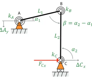
Torsion springs must be applied in all 3 hinges of the rocker slider mechanism in order to create the possibility to replace the rigid bodies by compliant segments. See illustration 2.5. The mechanism exhibits negative stiffness
2.2. DESIGN 7
C A
B
∆
[image:15.595.224.402.78.231.2]∆
!"
!Figure 2.5: The rocker slider mechanism having torions springs.
Table 2.1: Model parameters for rocker slider mechanism.
torsion stiffness [Nmm/rad] kA= 100·103 kB=kC= 1·103
link lengths [mm] L1= 20
L2= 15
initial coordinates of hinges A and C [mm] hAxi, Ayii=h0,15i hCxi, Cyii=h20,0i
range of motion [mm] ∆Cx= [−3...3]
pre-loading displacement [mm] ∆Ay=−1
For this mechanism the force displacement function can be explicitly found at point C in the horizontal direc-tion:
FCx=f(Cx) with Cx=Cxi+ ∆Cx (2.3)
See appendix D for the derivation of this function. The pre-loading is done by adding a negative value to the
initial y-coordinate of point A.
Ayi+ ∆Ay (2.4)
To study the behavior of the mechanism, a representative approximate set of values is chosen for the model parameters in the following way. See table 2.1. The origin of the coordinate system is placed such that coordinates
AxiandCyiare zero. Link 1 and 2 are about equal in length. As the size requirement restricts dimensions to
be below40[mm] a typical link length is set to the half of this value (for reasons explained in section 2.2.6).
Considering that hinges B and C are likely to be replaced by elastic joints some space needs to be reserved for this, that is why L2is chosen a bit smaller thanL1. PrescribingL1 andL2 to be perpendicular makes the geometry
fully determined. The torsion stiffness in hinge A is chosen such thatFCxshows realistic values (in the range of
15to20[N] based on the typical values listed in section 2.2.1), values for hinge B and C are chosen much lower. The magnitude of the range of motion∆Cxand the pre-loading displacement∆Ay are chosen such values that
they dont differ to much from the initial stress free geometry while non linear behavior is still visible. Now the model is fully determined and the force displacement graphs can be investigated through equation 2.3.
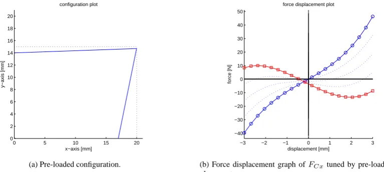
[image:15.595.160.464.289.391.2]8 CHAPTER 2. METHOD
results will be summarized below. Dotted lines in the configuration plots represent the stress free configuration, continuous lines represent the actual configuration for∆Cx = −3 [mm] and the full pre-loading displacement
∆Ay =−1. In the force deflection graphs the change of model parameter from initial to final value is indicated
[image:16.595.95.479.224.396.2]by lines with circles (initial) and by lines with squares (final). Dotted lines lying in between the initial and final graphs are incremental solutions.
Figure 2.6b presents the results of the incremental change of the pre-loading displacement until its final value. It can be observed that the system turns from stable to unstable. Figure 2.6a shows the corresponding geometry of the mechanism. The pre-loading displacement acts as a tuning parameter of the negative stiffness. During tuning
the unstable equilibrium point shifts a little bit to the right side.
0 5 10 15 20
0 2 4 6 8 10 12 14 16 18 20 x−axis [mm] y−axis [mm] configuration plot
(a) Pre-loaded configuration.
−3 −2 −1 0 1 2 3
−40 −30 −20 −10 0 10 20 30 40 50 displacement [mm] force [N]
force displacement plot
(b) Force displacement graph ofFCxtuned by pre-loading
dis-placement.
Figure 2.6: GUI simulation of rigid body mechanism, tuning the pre-loading displacement.
The negative stiffness will increase when torsion stiffness A increases relative to B and C. Nearly the same increasing effect is seen when link lengthL1is shortened while both links are kept perpendicular in the stress free
configuration. This is illustrated in figure 2.7.
−3 −2 −1 0 1 2 3
−25 −20 −15 −10 −5 0 5 10 15 20 25 displacement [mm] force [N]
[image:16.595.326.471.224.377.2]force displacement plot
Figure 2.7: GUI simulation, effect of tuning torsion stiffness values and link lenghtL1
Varying the angle of link 2 around vertical orientation in the stress free configuration has significant influence on the behavior. Decreasing or increasing the angle from vertical orientation causes a large forward or backward
shift of the force deflection graph. See figure 2.8.
[image:16.595.209.356.493.642.2]2.2. DESIGN 9
0 5 10 15 20
0 2 4 6 8 10 12 14 16 18 20 x−axis [mm] y−axis [mm] configuration plot
(a) Configuration for rotational offset of linkL2in stress free con-figuration.
−3 −2 −1 0 1 2 3
−10 −5 0 5 10 15 20 displacement [mm] force [N]
force displacement plot
[image:17.595.354.499.83.235.2](b) Large shift of force displacement graph due to rotational offset.
Figure 2.8: GUI simulation of tuning rotational offset of linkL2.
From these observations the following conclusions can be drawn. When designing for negative stiffness the
ratio between the stiffness in hinge A should be maximized relative to B and C. Both links may be perpendicular to each other in stress free configuration. Any deviation from perpendicularity only causes undesired shifting of the
force deflection graph. The length of link 1 should be decreased. While the length of link 2 should be maximized to improve the linearity of the behavior, see appendix F.
2.2.6
monolithic design
After identifying the main design variables, a fully compliant geometry may be derived to replace the rigid body mechanism. See figure 2.9.
[image:17.595.159.468.458.546.2]A B C A B C A B C
Figure 2.9: The rocker slider mechanism (on the left) converted to a version (in the middle) which may be replaced by a compliant geometry (on the right).
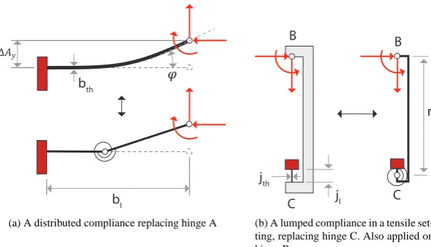
The torsion stiffness in hinge A should be high. The pre-loading displacement will then develop a high vertical force in hinge B, increasing the negative stiffness. This is proven in the last section of appendix D. To prevent high stresses a distributed compliance is chosen to replace link 1. See figure 2.10a.
Torsion stiffness in hinge B and C should be low. Lumped compliances are used to realize elastic joints
that have well defined hinge locations. Several common solutions are available for lumped compliances [8]. To simplify the design process a leaf spring shape is chosen. In this case the joints should transmit a high vertical force in points B and C. Then compressive stresses are unwanted since they easily could buckle the slender leaf
spring shape, thus a ”tensile setting” is applied. Finally link 2 is replaced by a rigid body having leaf spring shaped lumped compliances at both ends in a tensile setting as illustrated in the figures 2.10b and 2.9 on the right.
10 CHAPTER 2. METHOD
bth
bl
∆
(a) A distributed compliance replacing hinge A
B
C jth
rl
jl
B
C
[image:18.595.129.440.78.256.2](b) A lumped compliance in a tensile set-ting, replacing hinge C. Also applied on hinge B.
Figure 2.10: Replacing the rigid bodies of the rocker slider mechanism.
tuning the negative stiffness then a straight line guidance for vertical displacement is needed at point A too. The
design may be mirrored two times to get rid of the need for straight line guidance at both points. This is done over the horizontal axis and over the vertical axis. See figure 2.11.
A disadvantage of mirroring is that the size of the mechanism is doubled in two directions, for that reason link length 2 is initially taken less than half (15[mm]) of the size requirement. On the other hand, the mirror operation
over the vertical axis has as consequence (i) an equilibrium point insensitive to the shifting due to the pre-loading (see fig. 2.6b) and (ii) a four times increased negative stiffness. See appendix G for detailed information about mirroring.
shuttle
rigid link
compliant joint pre-loading beam
Figure 2.11: Mirroring the partial compliant solution vertically and horizontally.
2.2.7
dimensions
Final dimensions need to be obtained such that (i) it is suitable for the manufacturing method and (ii) for not exceeding the maximal allowable stress while maximal negative stiffness is exposed. This is done by some rough hand calculations as summarized below following the next line of thought.
The elastic joint is recognized as the most critical part of the mechanism. It has to transmit the maximal
[image:18.595.83.492.432.579.2]2.2. DESIGN 11 the elastic joint) conveying the induction of a bending moment.
The resulting bending and tensile stresses (summed together) should stay below the allowable stress which is set to500[MPa]. The selected material is titanium grade5, with a Young’s modulus of113.9[MPa]. In order to
maximize the tensile force the portion of bending stress should be minimal. This means that bending deformation should be kept small. Thus (i) having a small range of motion compared to the mechanism size and (ii) having
small rotations at the tip of the pre-loading beam due to pre-loading. Since loading and deflection are meant to be in-plane, a relatively large out-of-plane thickness ofw= 6[mm] is chosen to prevent any out-of-plane deflection effects due to asymmetric loading.
Elastic hinge
Since the equivalent torsion stiffness needs to be minimized, the smallest producible thicknessjthis assumed for
the elastic hinge (see figure 2.10b), which is about0.2[mm] in case of wire EDM. Taking a length thickness ratio
of10makes the lengthjl= 2[mm] and by that guarantees slenderness of this elastic segment. The lengthrlof the
stiff part is limited by the design requirement of40[mm]. Extra space for the elastic hinges is needed, so a length
of approximately 15 [mm] is taken into account. When a portion of 2/3 of the allowable stress is set for tensile stress then 1/3 is set for the bending stress. This results in a maximal allowable tensile force of400[N].
Pre-loading beam
The pre-loading beam is considered to be a one sided clamped beam with lateral loading at the tip (see figure 2.10a). So for small deflections the next force deflection relations from linear beam theory apply.
∆Ay= F·b3
l
3·E·I (2.5)
ϕ= F·b 2
l
2·E·I (2.6)
I= 1 12·w·b
3
th (2.7)
The load amounts400[N] as prescribed by the elastic hinge. Minimizing tip rotations can be achieved by designing a beam having low length/thickness ratio (bl/bth). For this reason the pre-loading displacement is
assumed to be small but still tunable, that is∆Ay = 0.2[mm]. Using formula 2.5 and 2.7 the length thickness
ratio becomes then:
bl bth
= 3
r
∆Ay·E·w
4·F ≈4.40 [−] (2.8)
Using 2.6 and 2.7 gives a tip rotation of approximately:
ϕ= 6·F
E·w· b
l bth
2
≈6.80·10−5 [rad] (2.9)
Knowing this ratio, choosing a lengthblor thicknessbth gives the final dimensions of the prelaod beam. The
length will be considered (rather then the thickness) since it was explored as a design variable in section 2.2.5. Decreasing the length will improve the negative stiffness, but also increase bending stresses. Another possible
12 CHAPTER 2. METHOD
set to below30[mm]. Final dimensions become then: length29.5[mm] and thickness6.8[mm]. This results in to a bending stress of260[MPa].
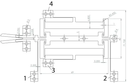
To prevent stress concentrations at corners, a fillet of radius0.45[mm] is applied. In figure 2.12 the final design
is shown. Leaf springs 3 and 4 are added for straight line guidance for measurement purposes, they can be omitted in case of application to a surgical tool.
[image:20.595.67.503.168.453.2]0,2 50 2 ,0 0 8 3 4 1 0,200 5 6 ,8 0 0 7 1 ,7 5 0 0,300 R0,4 50 4 0 69
4
3
1
2
Figure 2.12: The final geometry of a monolithical statically balanced grasper. Main dimensions are shown.
2.3
Evaluation
2.3.1
Obtained design
To evaluate the obtained design a finite element model is used (non linear analysis) to predict the force deflection behavior of the balancer and the grasper individually, and to check for the maximal stresses. See appendix B for
a detailed description. Also a linear pre-buckling analysis is done on the balancer model to check for unwanted low stiffness modes which may occur close to the pre-loading force, such as a rotational mode of the shuttle. See
appendix H for details. Important results are summarized in section 3.
2.3.2
Experiment
Experimental validation of the design is done by measuring the force deflection characteristics of a manufactured
2.3. EVALUATION 13 1. force deflection graph of grasper: point 1 and 2 are fixed, point 3 and 4 are free. No pre-loading is applied
at point 5 and 6.
2. force deflection graph of grasper and balancer: points 1,2,3 and 4 are fixed. No pre-loading is applied at
point 5 and 6.
3. force deflection graph of grasper and balancer while pre-loaded. points 1,2,3,4 are fixed. At point 5 and 6 a
pre-loading displacement is applied.
4. force deflection graph of balancer. Points 3 and 4 are fixed, 1 and 2 are free, pre-load is applied at 5 and 6.
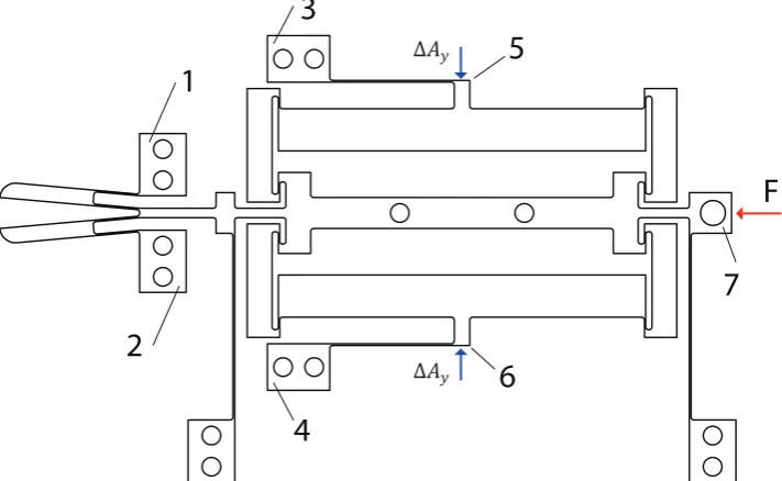
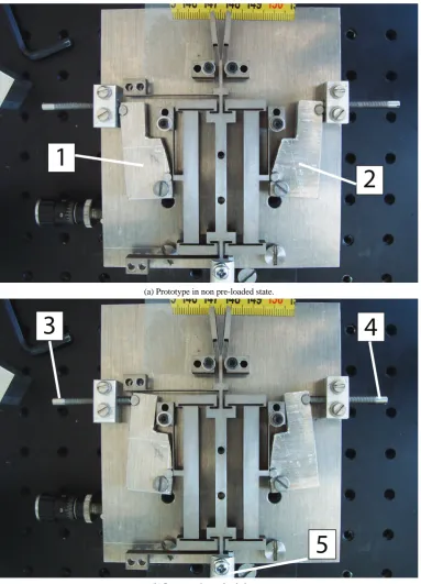
See the 2 pictures below (figure 2.14) for the measurement setup. They show the monolithic design fitted in
the measurement setup for the non pre-loaded state and the pre-loaded state. The levers (1,2) are used to pre-load the mechanism accurately by prescribing a displacement using the tuning screws (3,4). The pre-loading force is
not measured. At point 5 the connecting rod to the force sensor and linear actuation stage can be seen. Important results are discussed in chapter 3. A detailed measurement report can be found in appendix L.
1
2
3
4
5
6
7
F
∆ !
[image:21.595.135.491.307.526.2]∆ !
Figure 2.13: Schematic view of measurement method for different load cases.
2.3.3
Design approach
To evaluate the design approach the justification of using a rigid body mechanism for the behavioral study of the
compliant mechanism is investigated. This is firstly done by a strain energy analysis using the finite element model. For specific parts of the model the strain energy is calculated, the distribution of strain energy over several parts is compared to the energy characteristics of the rocker slider mechanism. See appendix I for detailed information on
the strain energy analysis. Secondly the pseudo rigid body modeling method is applied to the final design to obtain a more accurate force deflection graph from the rocker slider model (see appendix J). This graph is compared to
the prediction of the finite element model. Additionally a sensitivity analysis for design variables is performed for the finite element model and the pseudo rigid body model. Those results are compared for both models with the
14 CHAPTER 2. METHOD
1
2
(a) Prototype in non pre-loaded state.
3
4
5
[image:22.595.94.478.134.666.2](b) Prototype in pre-loaded state.
Chapter 3
Results
3.1
Model predictions
Grasper and balancer are both individually modeled and analyzed through non linear finite element analysis using displacement control. The simulation shows that the balancer generates approximately enough negative stiffness
to compensate the positive stiffness of the grasper. See figure 3.1. The maximal occurring equivalent stress is 555 [MPa] for the balancer and 531 [MPa] for the grasper. See appendix B for more details.
−0.2 −0.1 0 0.1 0.2 0.3
−30 −20 −10 0 10 20 30
displacement [mm]
force [N]
balancer grasper
[image:23.595.180.440.391.591.2]balancer + grasper
Figure 3.1: FE simulations of the balancer and the grasper individually. Both results are added afterwards to predict the behavior of the balanced mechanism.
3.2
Measurement of the prototype
The wire EDM fabricated design is pictured in figure 3.2.
Force deflection data resulting from the experiment as described in the section 2.3 (Evaluation) are plotted in figure 3.3. Detailed measurement information is contained in appendix K. The red circles in the graphs indicate the starting point (grasper is fully open) in the range of motion during measurement.
16 CHAPTER 3. RESULTS
Figure 3.2: Prototype manufactured by wire EDM.
Table 3.1: The energy balance calculated based on measurement data.
case remark energy in [mJ] energy out [mJ] hysterisis [mJ] case 1 unbalanced mechanism 5.6819 -5.5800 0.1019 case 2 constant positive force 0.8242 -0.7749 0.0492 case 3 constant negative force 1.5851 -1.5099 0.0752 case 4 bistable 0.5023 -0.4369 0.0653
In load case 1 and 2, see figure 3.3a, one can see the difference in positive stiffness of the grasper and the
combination of grasper and balancer without pre-loading. The positive stiffness of the balancer alone is thus much lower than the grasper. Both load cases expose nearly linear behavior. When pre-loading is applied, see load case
3 in figure 3.3b, the positive stiffness is drastically influenced. The range of motion is taken smaller (0.6 instead of 0.8 [mm]) for reasons related to out-of-plane deflection. This is explained in the measurement report, see appendix
L. The results in terms of energy and hysteresis are listed in table 3.1.
The results of load case 4 are figured in 3.4 and listed in table 3.2. The negative stiffness is approximated by the
formulak= ∆F/∆xusing the entire measurement range for∆Fand∆y. Pre-load displacement is incrementally raised to a value of approximately0.25[mm]. Thereby the negative stiffness of the balancer is clearly tuned. The position of the equilibrium point is hardly influenced by the pre-loading.
3.3
Model validation
3.3.1
Comparison between the measurement data and the model predictions
[image:24.595.106.466.397.462.2]3.3. MODEL VALIDATION 17
−400 −300 −200 −100 0 100 200 300 400 −25 −20 −15 −10 −5 0 5 10 15 20 25 displacement [mu] force [N]
loadcase 2 →
← loadcase 1
(a) Load case 1 having positive stiffness of 56 N/mm and load case 2 having 60 N/mm over a range of 0.8 mm.
−300 −200 −100 0 100 200 −20 −15 −10 −5 0 5 10 15 20 displacement [mu] force [N]
case 1 →
↓ case 2
case 3 ↑
case 4↑
[image:25.595.332.516.84.236.2](b) Load case 3 showing different measurement results over a range of 0.6 mm, the unbalanced behavior (case 1), two constant force behaviors (case 2 and 3) and one bistable behavior (case 4).
[image:25.595.104.286.88.235.2]Figure 3.3: Measurement results of different loadcases and settings.
Table 3.2: Negative stiffness and hysteresis values calculated based on measurement data.
nr negative stiffness [N/mm] linear correlation [-] hysteresis [mJ]
1 -7.82 -0.99785 0.0159
2 -17.47 -0.99948 0.0539
3 -25.29 -0.99964 0.0786
4 -36.13 -0.99973 0.1273
5 -45.96 -0.99979 0.1953
6 -58.53 -0.99980 0.3297
7 -68.53 -0.99982 0.5149
of settings of the applied load case during the experiment. In theory the three results should be close to each other. But the comparison shows a significant deviation, however the measurement data and both models show the
desired linear negative stiffness.
3.3.2
Sensitivity analysis
The design variables are changed in order to determine the sensitivities of both models. It is found that both models
predict equal behavioral changes, in magnitude and shape, for all design variables individually (see appendix K). To illustrate this result two graphs are plotted predicting change of behavior due to a combination of assumed fabrication tolerances on the geometry for both models. See figure 3.6.
3.3.3
FE strain energy analysis
A strain energy analysis is performed on the finite element model. For specific areas (see figure 3.7) of the mechanism the strain energy is calculated in two states of loading. When the mechanism is pre-loaded in its initial stress free configuration and when the mechanism reaches the maximal deflection in its range of motion
(while pre-loaded). When the elastic energy used for pre-loading is set to 100 [%] it is observed that area 1 has the largest energy release (-3.23 [%]). Area 3 and the combination of areas 5 and 6 release respectively -0.50 [%] and
-0.25 [%]. Area 2 hardly releases or accumulates energy (0.00 [%]) while area 4 is consuming 0.05 [%].
18 CHAPTER 3. RESULTS
−500 −400 −300 −200 −100 0 100 200 300 400 −30
−20 −10 0 10 20 30
displacement [mu]
force [N]
[image:26.595.154.404.90.296.2]1 → 2 → 3 → 4 → 5 → 6 → 7 →
Figure 3.4: Load case 4 measured over a range of 0.82 [mm]
When full range of motion is considered (motion from one elastic stable equilibrium to the other: [-1.1...1.1] [mm]) the total released energy increases up to 83 [%], while maximal stress is raised to about 977 [MPa].
The result is that the pre-loading beam is mainly responsible for the energy storage and release and thus has an
equal function compared to torsion spring A in the rocker-coupler-slider mechanism. Details of the energy analysis can be found in appendix I.
3.3.4
Linear pre-buckling analysis
Linear pre-buckling analysis results indicate that the balancer shows a buckling mode equal to the desired range of motion at relatively low critical load (57 [N]) compared to the predicted pre-loading force (330 [N], see
ap-pendix B). See figure 3.8. Since buckling modes are calculated under infinitesimal displacement assumptions their magnitude have no more physical meaning then just the initial shape of deformation. The zero stiffness mode is
predicted correctly by the stress stiffening effect using only the linear stiffness matrix of the FE model. See details of this analysis in appendix H.
3.3.5
Numerical scheme for RBM simulation
A numerical scheme is developed which, combined with a graphical user interface, enables to quickly analyze the transition from stability to instability of elastic systems resulting from the rigid body replacement method. The effect of change in design variables on the unstable behavior can be studied with low computational effort compared
to non linear finite element modeling. See appendix E for a detailed description of the developed numerical scheme and graphical user interface.
The low computational effort can be illustrated by comparing roughly the number of matrix inversions needed
to obtain the same results. This is done for a resolution of the force deflection graph of 25 points in the displacement range and 25 points in the pre-loading displacement range.
3.3. MODEL VALIDATION 19
−0.4 −0.3 −0.2 −0.1 0 0.1 0.2 0.3 0.4 −60 −40 −20 0 20 40 60 deflection [mm] force [N]
measurement ↑
[image:27.595.182.435.91.296.2]measurement FEM nominal PRBM nominal
Figure 3.5: Comparison of measurement data and predictions by PRB model and FE model.
−0.4 −0.3 −0.2 −0.1 0 0.1 0.2 0.3 0.4 −60 −40 −20 0 20 40 60 deflection [mm] force [N]
measurement ↑
FEM nom FEM min FEM max
(a) Finite element model.
−0.4 −0.3 −0.2 −0.1 0 0.1 0.2 0.3 0.4 −60 −40 −20 0 20 40 60 deflection [mm] force [N]
measurement ↑
PRBM nom PRBM min PRBM max
(b) Pseudo rigid body model.
Figure 3.6: Maximal expected change of behavior due to a combination of fabricational tolerances for both models
[image:27.595.107.514.344.509.2]20 CHAPTER 3. RESULTS
area1
area3
area2
area4
[image:28.595.56.475.108.342.2]area5
Figure 3.7: Definition of areas over which the strain energy is calculated.
[image:28.595.124.447.443.690.2]3.3. MODEL VALIDATION 21
Chapter 4
Conclusion
For the first time a statically balanced fully complaint grasper is successfully designed and prototyped using the
rigid body replacement method. The prototype meets the size requirement of 40 [mm], when all leaf springs for straight line guidance are omitted. The low hysteresis value of 1.32 [%] combined with the high force reduction factor of 98.92 [%] (see figure 2.1) shows that this design can improve the force feedback of a compliant surgical
grasper in a monolithic way. Although a zero force measurement was not obtained, the experimental results prove that this is certainly achievable when the equilibrium positions of the grasper and balancer are tunable with respect
to each other. Then the force reduction will lead to near zero force over the required range of motion.
The novel design widens the perspective on the field of designing statically balanced fully compliant mecha-nisms. The nominal finite element and pseudo rigid body models predict similar behaviors with the same significant
deviation from the experimental data. Both models show that the magnitude of uncertainty of the pre-loading dis-placement during the experiment has a large effect on the behavior. This behavior can drift into big deviations by
considering uncertainty in material and geometrical parameters. The pseudo rigid body model comes close to the finite element model, since the pseudo rigid body model is a gross approximation a deviation as shown may be
expected. The sensitivities for both models are similar. Their equivalence is supported by the strain energy analy-sis. Summarizing it can be concluded that the pseudo rigid body model is an accurate modeling method, provided that the deviation can be explained through the mentioned uncertainties. It is a modeling method that requires low
computational effort and provides high intuitive support.
Chapter 5
Discussion
5.1
The design
There is a lot of space for improvement of the particular design presented in this work, since no optimization has
been performed. Therefore it is expected that the size may be scaled down significantly. This might be achieved by choosing smaller dimensions for the pre-loading beam, or by choosing for a alternative solution for the pre-loading beam as shown in figure 5.1. The following steps may be taken towards down scaling:
mirror axis
mirror axis
Ppreload
Pactuation
h
Figure 5.1: Replacing the pre-loading beam for a straight line guidance to prevent rotation at the tip. The leafspring thicknesshcan be designed for pre-loading displacement versus force.
• The lenght of the prelaod beam may be decreased significantly, since no rotational low stiffness mode of the shuttle is expected and the estimated bending stresses are quite low.
• From the sensitivity analysis it follows that decreasing the length of link 2 and increasing the length of the compliant joint will increase the negative stiffness.
• Mirroring over the horizontal axis might be omitted if straight line guidance is implied otherwise, see figure 5.2, reducing the overall size of the balancer.
• An optimal value for the joint thickness might be found, at which the negative stiffness is maximized, since the elastic joint transmits a large tensile force (maximum thickness) while accounting for the bending stresses (minimize thickness).
26 CHAPTER 5. DISCUSSION
Pactuation
Pactuation Ppreload
[image:34.595.203.366.78.264.2]Ppreload
Figure 5.2: When mirroring is ommitted then straight line guidance of the shuttle and the pre-loading displacement can be achieved through adding the leafsprings as illustrated.
If the size is reduced while the negative stiffness and pre-loading force remain constant then this is the same as having a constant size and negative stiffness while the pre-loading force is decreased. Reducing the required
pre-loading force also means decreasing the out-of-plane thickness of the design.
The required pre-loading displacement is very small which caused troubles in precise determination of its value
during the experiment. Consequently the validation of both models was subject to large uncertainties. The pre-loading displacement can be increased easily by using the alternative solution in figure 5.1 through decreasingh.
Also no problems are to be expected when a more convenient length thickness ratio (see equation 2.8) is assumed for the pre-loading beam.
Apart from improving the negative stiffness, steps can be taken towards the application to a surgical tool. Finding a simple way of switching the pre-loading on and off is recommended in order to avoid stress relaxation effects. Furthermore when negative stiffness is increased, adding more positive stiffness segments is allowed
creating possibilities to develop a complete tool having compliant handles in a monolithic way. A preview of such a tool might look like figure 5.3.
Besides application in a surgical tool, the adjustability via pre-loading displacement of the constant negative stiffness of the balancer makes it an attractive alternative for the negative stiffness building blocks proposed by
Hoetmer [5].
5.2
The method
A weak spot in the taken design approach is the determination of shapes and dimensions of the monolithic
geom-etry. When a rigid body mechanism is designed (link lengths, torsion stiffness values and initial configuration are known) there is no guarantee that a replacing compliant version will be found which shows equivalent behavior.
There is also no guarantee that when a compliant version is found it will be the best solution, and does not exceed the allowable equivalent stress. Thus the taken approach seems to have mainly an added value for the synthesis
step in the design process.
To improve the added value, the model parameters of the rigid body mechanism might be coupled to predefined
5.2. THE METHOD 27
trigger
switch
handle
grasper
lever system
[image:35.595.104.533.72.349.2]balancer
Figure 5.3: An impression of how the balancer might be applied in a surgical tool in the future.
defined in the software, the user can quickly determine which one fits best. The software might even automatically
determine the best shape and propose it to the user.
Thus the software used in this work may be developed further to model the 4 bar mechanism in general. This
allows for generation of many different mechanisms and configurations of which the behavior and replace ability with compliant segments can by analyzed quickly by the designer. This may be applied in the beginning of the design process of a SBFC mechanism. The proposed candidate solution may then be optimized to a final design
based on its finite element model.
For the particular design presented in this work only small deflections are considered compared to the overall
Appendix A
Review of design approaches for statically
balanced compliant mechanisms
abstract
This paper aims to be an investigation of the state of the art of designing statically balanced compliant
mechanisms. Often abbreviated as SBCM. SBCM are beneficial because they combine the advantages of
a compliant mechanism (no backlash and sliding friction) and a statically balanced system (no external
force is needed to achieve displacements). The mathematical criteria for static balance are known. One of
them is that the stiffness matrix is singular. But there is no design method directly available to achieve this.
Although there are several theoretic areas that relate to statically balanced compliant mechanisms via the
more generally known property neutral stability. The objective is to make an inventory of related theoretical
areas in the field of neutral stability. To see how areas are related and what their overlap is with statically
balanced compliant mechanisms. To develop vision for design. This might lead to new ideas for
approaches to a design method. One existing design approach is identified, the so called building block
approach. Areas found to be related are: linear buckling, postbuckling, analysis of neutrally stable
mechanisms, vibration isolation, exact constraint design, Non linear spring design. These areas indicate
that design doesn’t necessarily has to be seen as a building block problem. The conclusion is that neutral
stability for some finite range can be achieved by applying a certain pre-stress distribution to a certain
geometry. This translates into a stiffness matrix being singular. Two hints towards ideas in how to achieve
singularity are mentioned: the first is based on exact constraint design and the second on a scalar
stiffness description.
introduction: background
A mechanism is a physical structure, often composed out of several hinged parts, designed to transfer
force and motion, see figure 1. Motion is typically achieved by relative movement of rigid parts through
joints. A compliant mechanism (abbreviated with CM) achieves motion by elastic deformation of its own
geometry, thus by lowering stiffness in one specific direction compared to all other directions, see figure 2.
A statically balanced compliant mechanism (abbreviated with SBCM) achieves elastic deformation without
applying any actuation force. Statically balanced compliant mechanisms are promising because of the
advantages listed in Table 1 [1].
Print http://test.ibtoon.nl/print.php
figure 1: mechanism
figure 2: compliant mechanism
The absence for the need of an actuation force to overcome the elastic deformation is a remarkable property,
but nevertheless mechanically possible [2] [3]. The property of static balance is generally known in literature
as neutral stability. Real world examples proving this property are discussed in Section 3. Unfortunately the
advantages are counter acted by some disadvantages listed in Table 2.
Table 1: advantages of (statically balanced) compliant mechanisms
advantages
explanation
CM: No backlash
Hinges and such are absent, motion is a result of elastic deformation.
CM: No sliding friction
CM: Monolithic
Can be manufactured out of one piece, no assembly is needed.
SBCM: Energy efficient No actuation force needed to deform elastically.
SBCM: Force feedback Force feedback is convenient in case of human control of the mechanism [4].
Table 2: disadvantages of statically balanced compliant mechanisms
disadvantages
explanation
Increase in size
A statically balanced compliant mechanism tends to be larger in size then the unbalanced
version. This is discussed in Section 4.
Increase in
hysteresis
Decreasing the demanded actuation force implies that possible occurring hysteresis
effects become relatively more dominant [5].
Little
understanding
Analysis is not straight forward which limits the understanding of the behavior. This is
because compliant design is challenging by itself [6] and besides that nonlinear behavior
is likely to be involved [7].Another limiting factor for understanding is that the property of
neutral stability is in general not pursued as a design goal in literature. Being the border
between stable and unstable behavior, neutral stability is naturally avoided in most cases
[8].
No design
methods
There are no design methods available. Mainly because of the little understanding of the
behavior.
Print http://test.ibtoon.nl/print.php
[image:39.595.356.501.42.341.2]introduction: problem statement
The problem statement is formulated by first discussing what is known about SBCM, and then what still
remains unknown.
What is known about static balance for compliant mechanisms ?
In [1] some criteria are derived which define static balance for a range of motion for a mechanism which may
be compliant or not. The criteria apply in general for discretized mathematical models, for example a finite
element model of a elastic structure. The vector
x
̲
contains the degrees of freedom of the model which are
displacements. A preliminary investigation is made to determine if the criteria suit the design methods for
compliant mechanisms discussed in [6]. Three relevant criteria which are based on the principle of work [9]
are listed in Table 3.
Table 3: criteria for statically balanced mechanisms for some range of motion
x
̲
criterion
explanation
relation
Constant potential
energy
U
(
x
̲
)
= constant
(1)
Elastic energy is internally exchanged, no work is supplied to or
generated by the system.
U
(
x
̲
)
= constant
(2)
Continuous
equilibrium
∑
F
i(
x
̲
)
= 0
(3)
Internal elastic forces add up to a resultant force which is zero,
irrespective of the motion.
__
F
:=
∂
U
(
x
̲
)
∂
x
̲
(4)
Zero stiffness
det
(
[
K
t(
x
̲
)
]
)
= 0
(5)
Stiffness relates force to displacement. When no force is needed to
obtain displacement, stiffness is zero. The tangent stiffness matrix
becomes singular. See remark below.
[
K
t]
:=
∂
2U
(
x
̲
)
∂
x
̲
2(6)
Remark:
when no force is needed to obtain displacement for an elastic mechanism it is easy to see that then stiffness
must be zero, especially for a one degree of freedom system:
k
⋅
x = F
→
k
⋅
x = 0
→
x
≠
0 thus k = 0
(7)
It is less clear that for a multi degree of freedom system it also means that the tangent stiffness matrix must
be singular. To see this, consider the next situation for a general linearized system which is only valid for
small variations of displacements
∆
__
_
x
and forces
∆
_ _
_
F
. Then the linear equation holds:
[
K
t]
⋅
∆
__
_
x
=
∆
_ _
_
F
(8)
Suppose that by magic the system gained some how the special property of neutral stability, then with zero
load there should still be displacement unequal to zero possible. These displacements satisfy then the
homogenous equation:
[
K
t]
⋅
∆
__
_
x
= 0
̲
(9)
So there are more solutions for
__
∆
_
x
besides the trivial one:
__
∆
_
x
= 0
̲
. The non zero solutions for
∆
__
_
x
form the so
called null space of the matrix. This is only possible when the matrix is singular [10 - Private]. Or in other
words when the system is linear dependent. The number of equations is less than the number of unknowns,
so there is no unique solution possible and there is at least one free variable. When such a linear system is
elaborated into the echelon form then it also can be seen that the determinant is zero [10]. Thus:
det
([
K
t])
= 0
(10)
Print http://test.ibtoon.nl/print.php
What is not known ?
It is not known how the criteria can quickly lead to a large number of use full designs. A method is not directly
available. Although there are several theoretic areas that relate to SBCM via the more generally known
property of neutral stability.
introduction: objective
The objective is to make an inventory of related theoretical areas in the field of neutral stability. To see
how areas are related and what their overlap is with SBCM. And eventually to develop vision for design of
SBCM. This might lead to new ideas for approaches to a design method.
introduction: structure
This paper is structured as follows. In section 2 the search method will be described. In section 3 the
results of the method will be presented. In section 4 the results will be discussed and in section 5 a final
conclusion is stated.
method
Table 4 summarizes the sources and key words used in the search for literature. The keywords listed
indicate the encountered fields, buckling and SBCM. Several combinations of the keywords where used,
only search results of less then 50 items where accepted for further processing.
Table 4: sources and keywords used for literature research
Sources
Keywords
Scopus: http://www.scopus.com/ mainly scientific
publications
zero stiffness, neutral stability, buckling,
bifurcation, static balancing, compliant
mechanisms
IMR: (research group TU Delft) mainly conference
proceedings and scientific publications
Other: (TU Delft Library, private book collection,
internet) mainly books
results
In this section the areas in literature found to be related to neutral stability are described and the relation is
explained per area.
Area: linear buckling
In linear buckling analysis an eigenvalue problem is derived [11]. This eigenvalue problem can be derived
from the tangent stiffness matrix of the system [12]. The tangent stiffness matrix can be represented by a
sum of two matrices:
linear stiffness matrix: accounting for the linear stiffness
1.
stress stiffness matrix: accounting for the (change of) stiffness induced by the preload force.
2.
By dictating the tangent stiffness matrix to be singular the system of equations will exhibit the eigenvalue
Print http://test.ibtoon.nl/print.php
problem. The eigenvalues correspond to the critical loads and the eigenvectors to the buckling modes.
Having a singular stiffness matrix means having a null space spanned by the eigenvectors, as explained in
the Table 3. This way linear buckling is related to SBCM. This analysis is only valid for infinitesimal
displacements around one configuration.
Area: postbuckling
It is known that structures can carry loads exceeding their initial buckling load [13]. In post buckling the main
interest lays in understanding the behavior of the structure after the initial buckling load is exceeded. Then
the structure may become unstable or stable again. Positive, zero and as well negative stiffness can occur.
Meaning that the force displacement relation is nonlinear. Limit points have zero stiffness, bifurcation points
may branch into zero stiffness paths. Some conditions for zero stiffness bifurcation are studied in [14], they
apply to simple truss system. Most other work encountered focus on the influence of imperfections on post
buckling behavior and path calculation methods. Mainly column, truss, shell and plate like structures are
considered.
For shell and plate structures [15], truss systems forming domes [16] bipath [17] hiearchy.
The equilibrium path described by the increasingly loaded structure (and thus increasingly deforming
structure) also possibly covers zero stiffness (bifurcation) paths for a finite range of displacement. This
possibility links to SB.
Area: design of statically balanced compliant mechanisms (SBCM)
A few attempts have been made to design SBC mechanisms.
The earliest attempt found was in [3]. A proposal for a zero stiffness leaf spring guidance is made by
compensating with negative stiffness.
A longer design route was taken to end up with a SB laparoscopic grasper. In [18] a feasibility study is
done for conceptual design using a negative stiffness building block to balance the grasper. In [19]
another negative stiffness mechanism was conceptually designed and optimized. In [20] finally an
equally design was made and prototyped.
Then in [21] a design for SB flexure joint was made and prototyped by Morsch.
In [5] a negatieve stiffness is designed together with a positive stiffness gripper for SB.
A straight line guiding mechanism is designed and prototyped in [22]. A 2D mechanism having zero
stiffness for a large finite range of motion, and positive stiffness in any other in plane direction.
Recently a compliant finger is balanced in a large displacement range by a contra compliant
mechanism in [23].
All these design attempts have in common that a positive stiffness is added to a negative stiffness and thus
zero stiffness is approximated for a certain range of motion. Design is often done by optimization, by
minimizing stiffness or actuation force over the range of motion. To realize negative stiffness often two
fundamental types of mechanisms are used, a bi stable mechanism and an unstable mechanism. The first
one can be compliant by itself, the second one not and is to be translated to a compliant equivalent.
Area: analysis of neutrally stable mechanisms
TENSEGRITY: In [24] a zero stiffness tensegrity structure is analyzed, in [25] a design of tensegrity
mechanism zero stiffness is made an prototyped. The key property is the zero free length spring which
replaces all of the tensioning cables. This combined with matrix analysis presented in [26] and a tangent
stiffness matrix formation presented in [27] leads to a method to generate a family of tensegrity structures
which are SB for a large range of motion. The structures discussed are pin jointed and thus not compliant. It
is recommended to search for an equally generic theory for non-pin jointed structures.
SHELL: In [28] and [2] a neutrally stable elastic shell is presented. This is proven theoretically, and a
prototype is made to illustrate its behavior in reality. The shell is a solid piece of flat metal which is plastically
deformed in 2 different ways to create an initial stress distribution.
COMPOSITE SHELL: In [29] a composite shell is presented which is neutrally stable and its application in
Print http://test.ibtoon.nl/print.php
![Figure 2.1: Definition of the force reduction factor: (1 − F2/F1) · 100[%].](https://thumb-us.123doks.com/thumbv2/123dok_us/9915944.493391/12.595.120.450.74.354/figure-denition-force-reduction-factor-f-f.webp)
![Figure 2.2: Compliant grasper designed by van den Berg [4] in open and nearly closed configuration.](https://thumb-us.123doks.com/thumbv2/123dok_us/9915944.493391/13.595.108.522.81.201/figure-compliant-grasper-designed-berg-nearly-closed-conguration.webp)