Sensorless Speed Estimation of PMSM near
Zero Speed Using Online Short Time Fourier
Transform Ridges
G. El-Murr, D.Giaouris, and J.W. Finch
Abstract— There are many sensorless schemes that have been proposed to estimate the rotor speed and position. However high frequency signal injection methods are able to detect the rotor speed and position even at zero speed whereas other schemes fail. Conventionally such methods use estimators based on the phase locked loop structure, which involves some restriction to maintain stability and track accurately the rotor position. Recently the concept of instantaneous frequency has become useful in many engineering applications where it is used to describe time varying signals. In this paper an instantaneous frequency estimation scheme based on the short time Fourier transform ridges is proposed to detect the rotor speed. Theoretical and simulation aspects of the conventional and proposed method are discussed and results are compared.
Index Terms— Instantaneous frequency estimation, sensorless control.
NOMENCLATURE
c c i
u , High frequency voltage and current vectors in stationary reference frame
c c i
u′, ′ High frequency voltage and current vectors transferred to the rotor reference frame
c
u High frequency voltage amplitude c
ω Carrier frequency
r
ω Rotor velocity
αβ
,
dq Subscripts denoting rotor and stator direct and quadrature axis.
l Leakage inductance
^ denotes estimated quantities LPF Low pass filter
Manuscript received March 22, 2007.
The authors are with the School of Electrical, Electronic and Computer Engineering, Newcastle University, Newcastle upon Tyne, NE1 7RU, UK.
Corresponding author: D. Giaouris (phone +44-(0)191-222-7327; fax: +44-(0)191-222-8180; e-mail: Damian.Giaouris@ncl.ac.uk).
(other e-mails: georges.murr@ncl.ac.uk, j.w.finch@ncl.ac.uk).
I. INTRODUCTION
he main drawback in most of the parameter dependant sensorless techniques is their instability to work at low and zero speed. Only high frequency signal injection methods operate efficiently at very low and zero speed. In these high frequency signal injection methods [1]-[6] the stator resistance of the Permanent Magnet Synchronous Motor (PMSM), as well as the back-emf disturbances, can be neglected. As a result the rotor speed and position can be estimated by using the machine inductance variations due to saturation and geometrical effects. In the PMSM the stator inductances vary with respect to the rotor position. These variations arise even in surface-mounted PMSM. In such machine the saturation in the stator teeth will produce a direct-axis synchronous inductance smaller than the quadrature-axis synchronous inductance and these inductances vary with the rotor position.
To extract the information of the rotor position, the injected voltage can be either rotating [1], or pulsating [7], [8]. The resultant high frequency current is amplitude modulated by the error between the actual and the estimated rotor position. Conventionally, speed and position observers based on the Phase Locked Loop (PLL) structure are used to detect the rotor position. However, some restrictions are required for the PLL observer to maintain stability and produce accurate results. These are: the error between the estimated and actual rotor angle should be small, and the input carrier frequency should be synchronized with the demodulator carrier frequency. To overcome the PLL restrictions, a new demodulation technique is proposed. It is applicable for the rotating voltage injection method and the rotor speed can be determined using online Short Time Fourier Transform (STFT) Ridges.
The recent application of advanced signal processing techniques to electric drives [9], [10] has improved the performance of such systems. The main aspect of this paper is to introduce the possibility of using online STFT ridges in sensorless electric drives, to estimate instantaneously the rotor speed and position. Such techniques can be implemented on DSPs to perform the calculation of Fourier transformation and ridges algorithm. Theoretical analyses for the conventional and proposed methods are applied and the results are presented in section V.
II. HIGH FREQUENCY VOLTAGE INJECTION
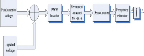
Position information is related to the inductance variations or (saliency) presented in the machine. By injecting a high frequency voltage superimposed on the fundamental voltage into the machine a transient state is created, and the resultant high frequency current signal is affected by the inductance variations of the machine. Fig.1 illustrates the general idea of the high frequency injection method.
ωˆ
[image:2.612.310.562.100.271.2]∫
δˆFig. 1: Block diagram of the high frequency injection scheme
In the cageless interior-PMSM the saliency exists due to the asymmetric structure of the motor and the d-q inductance difference is usually large. However for the surface mounted PMSM the magnetic anisotropy is induced by the saturation of the main flux [10]. The anisotropy is defined to be the d-q inductance difference induced by the magnetic flux saturation.
To reduce the effect of parameter dependency of the estimator especially at zero and very low speed, a rotating high frequency voltage signal (1) is injected into the PMSM, which has the characteristics shown in Table. I.
t jω
ce c u
= c
u (1)
The injected carrier frequency can be chosen to be between 600 Hz and 2 kHz depending on the machine characteristics and the sampling frequency of the inverter.
At high frequency, the motor model can be expressed as follows: dt d l c c i
u′ = ′ (2)
Thus the interaction of the high frequency injected voltage with the saliency of the machine produces a resultant high frequency current (3) modulated by the rotor frequency.
(
)
(
(
)
)
⎟⎟ ⎠ ⎞ ⎜ ⎜ ⎝ ⎛ − + + − − = ′ − − − )t ω j(ω d q )t ω j(ω q d q d r c c r c r c e l l e l l l l u j ω ω 2 ci (3)
The transformation of (3) to the stationary reference frame yields:
(
)
(
(
)
)
⎟⎟ ⎠ ⎞ ⎜ ⎜ ⎝ ⎛ − + + − − = + = −−j(ω ω)t
d q )t ω j( q d q d r c c r c c e l l e l l l l u j j 2
2 ω ω
cβ
cα
c i i
i (4)
In equation (4) the high frequency current signal consists of positive and negative sequence components. Only the negative sequence current component, which rotates at an angular velocity equal to −ωc+2ωrcontains the desired information concerning the rotor position.
To extract the information from the negative sequence
current component, the resultant high frequency current (4) is multiplied by another signal that rotates at an angular velocityωc−2ωˆr.
(
)
(
(
)
)
⎟⎟ ⎠ ⎞ ⎜ ⎜ ⎝ ⎛ − + + − − = − − )t ω ω j( d q t) ω t-ω j( q d q d r c c r r r c e l l e l l l l u j ˆ 2 2 ˆ 2 2 ˆ2ω ω ωr
c 2
ω
c
i (5)
The produced low frequency is represented in (6) and it is extracted by using a low-pass filter
(
)
(
(
q d)
j( ω ω )t)
q d r c
c l l e r r
l l ω ω u j
LPF ˆ 2 2ˆ
2 ) ( − − − − − = r c 2ω
ω
c
i (6)
The real part of equation (2.6) can be rewritten as:
(
)
l l δu LPF q d r c c sin )
( 2ˆ
ω ω ω − = − r c ω c
i (7)
For a small position difference:
δ
δ=∆
sin (8)
where is the error between the actual and estimated rotor position.
r r
∧
− =
∆δ δ δ
To minimise the error and lock on the actual rotor position a closed loop control system based on the PLL strategy is applied and (7) can be used as a corrective error to the speed, position observer after some repeatable operations.
Table. I Motor Parameters
Symbol Quantity Value (unit)
Vrated Rated voltage 400/460 (V)
P Pole pair 2
Rs Stator resistance 6.25 (Ω)
ld Stator d-axis
inductance
142 (mH)
lq Stator q-axis
inductance
380 (mH)
ωrated Rated speed 6000 (rpm)
III. PROPOSED DEMODULATION SCHEME
The PLL based observer may lose track in case of a large error between the actual and estimated angle. This is due to the nonlinearity of the resultant error (7) produced after low-passing the multiplication of the incoming signal and the reference signal. In addition if the oscillator frequency of the demodulator is not synchronized with the carrier input frequency an erroneous estimation will result. However, the nonlinearity problem can be solved by designing more sophisticated PLL but this will lead to a latency in the response and increase in the cost. Alternatively an additional higher order filter can be added to the drive to solve the noise interference problem. These filters can affect the performance and stability of the system.
[image:2.612.46.296.167.264.2](
)
( )
[
l l (ωt) l l (ωt ωt)]
(9)l l ω
V
i d q c d q c r
d q c
c
cα sin sin 2
2 + − − −
− =
(
)
[
l l (ωt) (l l ) (ωt ωt)]
ll ω
V
i d q c d q c r
d q c
c
cβ cos cos 2
2 + + − +
= (10)
) 2 sin( )
(i i K1K2 t
LPF cα× cβ = ωr (11)
where,
(
d q)
q d c
c l l
l l V
K = +
ω
2
1 and
(
q d)
q d c
c l l
l l V
K = −
ω
2
2
Also,icαand icβ are delayed by 4
π
, multiplied by each other and then filtered, the resultant equation is:
) 2 cos( )
(i i K1K2 t
LPF cα × cβ delayed = ωr (12)
Equations (11) and (12) represent the real and imaginary part of the demodulated signal, and they can be used to determine the speed and rotor position either by detecting the zero-crossing of sine wave in (11) or by using advanced instantaneous frequency estimation algorithm such as adaptive IF filters, Time-Frequency distribution, etc.
Hence if equation (11) or (12) has been used directly to estimate the speed and consequently the position, then the estimated speed result will be obtained after at least half of the rotor speed cycle. Thus it is impossible to use sensorless control since such a method requires an accurate instantaneous rotor speed and position estimation similar to the one provided by the transducer or encoder.
To solve the problem a frequency shift signal processing method described in equation (13) is suggested
(
)
t K K t t t t K K i r h h c h r h ) 2 sin( ) sin( ) 2 cos( ) cos( ) 2 sin( 2 1 2 1 ω ω ω ω ω ω + = × + × = (13) where ih is the resultant shifted signal, and ωh is the frequency by which the actual rotor frequency is shiftedBy using the frequency shift method, the time period which contains the information about the rotor speed becomes much smaller than the actual period. Therefore the estimator will be able to detect the instantaneous rotor speed and position in transient and steady state conditions.
IV. ONLINE STFT RIDGES METHOD USED TO ESTIMATE THE INSTANTANEOUS ROTOR SPEED
The Fourier Transform (FT) plays a fundamental role in the analysis of signals and time invariant linear systems. The efficiency of the FT is that it describes the relation between a signal in the time domain and frequency domain (14).
( )
+∞∫
∞ −−
= xt e dt
f
X j2πft
)
( (14)
where X(f) is the Fourier transform of x(t), and f is the variable frequency.
As shown in (14) the analysis coefficients of X(f) are computed as inner products of the signal with sine-wave functions of infinite duration. As a result of the infinite extent of the Fourier Transform the analysis is time averaged. Thus it contains only globally averaged information and so has the potential to hide
transients or the location of specific features within the signal. Consequently any abrupt change in time in a non-stationary (time varying) signal x(t) is spread out over the whole frequency.
This limitation can be partly overcome by introducing a sliding time window of fixed length to localize the analysis in time. This concept is called Short Time Fourier Transform (STFT), and is defined as:
( )
+∞∫
∞ −
−
−
= xt gt e dt
f
Sτ τ j2πft
) ( ) (
, (15)
where g(t-τ) is the sliding window function
For instantaneous time-frequency representation the spectrogram is commonly used in signal analysis to investigate the time frequency content of the signal. The spectrogram Ps(τ,f) is nothing more the STFT squared:
( )
2 2) ( ) ( ,
∫
∞ + ∞ − − −= xt gt e dt
f
Psτ τ j πft (16)
The energy spectral density E(f) describes how the energy of a (finite-energy) signal is distributed with frequency (17)
2 2 ) ( 2 1 ) (
∫
∞ + ∞ − −= xt e dt
f
E j πft
π (17)
The difference between (17) and (16) is the time localisation of the window function g(t). As a result the spectrogram representation can be defined as the distributed energy of a signal localised in the time boundary of the translated window function.
After briefly explaining the STFT and the spectrogram representation it is necessary to introduce the relation between the instantaneous frequency estimation concept and the spectrogram.
According to [12] the energy density of a signal is mainly concentrated around the instantaneous frequency, which means that the maximum time-frequency energy distribution is located around the instantaneous frequency. Thus the frequency can be estimated by extracting the peak value of the spectrogram and its associated frequency. This can be done by using the ridges algorithm [13], [14].
In sensorless control of PMSM the rotor speed should be estimated instantaneously integrated and fed-back to the controller Fig. 2. Therefore the STFT ridges estimator should estimate the rotor speed online. In a real time application the spectrogram of a signal can be found efficiently by using discrete-time STFT (18).
2 2 ) ( ) ( ) , (
∑
∞ + −∞ = − − = n fn j hs m f i n g n me
P π (18)
The time window of the spectrogram can be minimised by using equation (13). Thus the instantaneous frequency of the signal ih can be estimated rapidly by finding the maximum
Fig.2: Sensorless control block diagram using STFT Ridges algorithm
V. DISCUSSION AND RESULTS
The previous sections have discussed the conventional PLL method that has been used to estimate the rotor speed, and suggested a frequency estimation technique based on STFT ridges to avoid some disadvantages of the conventional technique.
To verify the performance of the proposed method, PMSM and the estimator have been modeled using Matlab, and the PMSM parameters used are shown in table 1. The band-pass filters used are Butterworth second order filters centered at 1.5 kHz with 400 Hz bandwidth, and the FFT length used in the STFT ridges estimator is 216.The amplitude of the injected voltage is 15 V and the carrier frequency is 1.5 kHz.
During the tests the voltage is applied directly to the machine without any control scheme. Thus the rotor speed is oscillating during the transient state due to the asynchronisation between the rotor flux and the stator flux at start-up region. Such test can be performed only at low speed due to the fact that the rotor flux will be able to lock on the stator flux after some delay. The estimator response of the PLL is presented in Fig. 3; the estimator is turned on after the machine reaches the steady state region. A large overshoot in the response is clear; this is due to the damping ratio of the PI controller and the difference between the actual and the estimated speed, at the beginning of the estimation process. However in Fig. 4 the overshoot has disappeared and the STFT ridges estimator reaches the steady state region even faster then the PLL observer.
In the following results, Fig. 5, both estimators have been tested during transient and steady state motor operation. The motor is subjected to a load to create a transient state on the rotor speed. A small variation occurs, due to the impact of the load, before the speed returns to the steady state value (6.5 Hz). In contrast to the PLL observer, the STFT ridges estimator is capable to detect the transient speed variation but with some delay due to the processing time.
Finally the speed estimators have been tested at zero speed. The rotor speed has been tracked accurately by the conventional and the proposed estimation technique. Nevertheless any variation of the stator resistance i.e. thermal effects, will not affect the performance of both estimators. This is related to the fact that the injection schemes depends only on the presence of saliency in the machine.
0 0.1 0.2 0.3 0.4 0.5 0.6 0.7 0.8 0.9 1
-15 -10 -5 0 5 10 15
Time
R
o
to
r S
p
ee
d (
H
z
)
Fig.3: Actual rotor speed, 6.9 Hz (solid line); PLL estimated speed (dashed line)
0 0.1 0.2 0.3 0.4 0.5 0.6 0.7 0.8 0.9 1
-15 -10 -5 0 5 10 15
Time (s)
R
o
to
r S
p
ee
d (
H
z
)
Fig.4: Actual rotor speed, 6.9 Hz (solid line); STFT ridges estimated speed (dashed line)
0 0.1 0.2 0.3 0.4 0.5 0.6 0.7 0.8 0.9 1
-20 -15 -10 -5 0 5 10 15 20 25
Time (s)
R
o
to
r S
p
e
e
d
(H
z
)
PLL Observer STFT Ridges Actual Speed
0 0.1 0.2 0.3 0.4 0.5 0.6 0.7 0.8 0.9 1 -15
-10 -5 0 5 10 15
Time (s)
Rot
o
r S
p
eed
(H
z)
Fig.6: Zero speed performance. Actual speed 6.9 Hz , then 0 Hz (solid line); PLL estimated (dashed line)
0 0.1 0.2 0.3 0.4 0.5 0.6 0.7 0.8 0.9 1
-15 -10 -5 0 5 10 15
Time (s)
Rot
o
r S
p
eed
(H
z)
Fig.7: Zero speed performance. Actual speed 6.9 Hz , then 0 Hz (solid line); STFT ridges estimated speed (dashed line)
VI. CONCLUSION
In this paper some of the PLL observer problems that can lead to erroneous results have been discussed. A new demodulation and speed estimator techniques have been suggested. The proposed scheme has shown a better performance than the conventional PLL but it requires additional computations. However, with advanced microcontroller and DSP technologies this problem is not so significant. In some applications the difference in d-q inductance can vary and becomes relatively small. Thus the SNR decreases and the PLL may loose track. The STFT ridges method used has additional advantage over the PLL is that it can operate at low SNR. High frequency injection is parameter independent, and operates efficiently at very low and zero speed
.
REFERENCES
[1] P.L. Jansen, M. Corley, and R.D. Lorenz, “Flux, position, and velocity estimation in AC machines at zero and low speed via tracking of frequency saliency”, Proc. EPE Conf., 1995, pp.154-160.
[2] Ji-Hoon Jang, Seung-ki Sul, Jung-Ik Ha, Kozo Ide, and Mitsujiro Sawamura, “Sensorless drive of surface-mounted permanent-magnet motor by high-frequency signal injection based on magnetic saliency” ,
IEEE Trans. Industry Appl, vol. 39, no. 4,pp:1031-1039, July/Aug 2003.
[3] M. Corley and R.D. Lorenz, “Rotor position and velocity estimation for a permanent magnet synchronous machine at standstill and high speeds”,
IEEE Trans. Industry Appl., vol. 34, pp.784-789, July/Aug 1998.
[4] Y. Jeong, R.D. Lorenz, T. M. Jahns, and S. Sul, “Initial rotor position estimation of an interior permanent magnet synchronous machine using carrier-frequency injection methods”, Proc. IEEE IEMDC, June 2003, pp. 1218-1223.
[5] T. Noguchi, K. Yamada, S. Kondo, and Takahashi, “Initial rotor position estimation method of sensorless PM synchronous motor with no sensitivity to armature resistance”, IEEE Trans. Ind. Electronics, vol. 45, pp. 118-125, Feb.1998.
[6] D. W. Chung, J.K. Kang, and S. Sul, “ Initial rotor position detection of PMSM at standstill without rotational transducer”, Proc. IEEE IEMDC, May 1999, pp.785-787.
[7] M. Linke, R. Kennel, J. Holtz, “Sensorless position control of permanent magnet synchronous machines without limitations at zero speed”, IEEE Annual conference, Industrial Electronics Society, vol. 1, pp. 674 – 679, Nov. 2002.
[8] M. W. Degner, R. D Lorenz, “Position estimation in induction machines utilizing rotor slot harmonics and carrier-frequency signal injection”,
IEEE Trans. Industry Appl., vol. 36, no.3, pp: 736-742, May/June2000.
[9] D. Giaouris, J.W. Finch, O.C. Ferreira, R.M. Kennel, G. El-Murr, “Wavelet Denoising for Electric Drives”, IEEE Trans. Ind. Electronics, to be published August 2007.
[10] J. M. Aller, T. G. Habetler, R. G. Harley, R. M. Tallam, and S.B Lee, “Sensorless speed measurement of AC machines using analytic wavelet transform”, IEEE Trans. Industry Appl., vol. 38,no. 5, Sept/Oct 2002. [11] J. Holtz, and H. Pan, “Acquisition of rotor anisotropy signals in sensorless
position control systems”, IEEE Trans. Industry Appl., vol. 40 no. 5, pp.1379-1387, Sep/Oct 2004.
[12] N. Delpart, B. Escudié, P. Guillemain, R. Kronland-Marinet, P. Tchamichian, B. Torésani, “ Asymptotic wavelet and Gabor analysis: extraction of instantaneous frequencies”, IEEE Trans. Inform. Theory, vol. 38, no.2, March 1992.
[13] N. Delpart, “Global frequency modulation laws extraction from the Gabor transform of a signal: a first study of the interacting components case”,
IEEE Trans. S peech Audio Processing, vol. 5, no. 1, January 1997.
[14] R. A. Carmona, W. L. Hwang, and B. Torrésani, “Characterization of signals by the ridges and their wavelet transforms”, IEEE Trans. Signal
Processing, vol. 45, no.10, October 1997.