Application of Topology Optimization and
Manufacturing Simulations - A new trend in
design of Aircraft components
Waqas Saleem, Fan Yuqing, Wang Yunqiao
Abstract—Structural optimization tools and computer simulations have gained the paramount importance in industrial applications as a result of innovative designs, reduced weight and cost effective products. Especially, in aircraft and automobile industries, topology optimization has become an integral part of the product design process. In this paper nonparametric topology optimization has been applied on a commercial aircraft vertical stabilizer component using ANSYS software. Suitable loads and constraints are applied on the initial design space of the component to accommodate for fin gust, rudder deflection, lateral gust, and other loads experienced by an aircraft during actual flight maneuvering. An integrated approach has also been developed to verify the structural performance and to overcome the problem of nonmanufacturable topology optimization results. Post machining distortions are also simulated by using element deactivation technique first by developing an initial residual stress field through Sequential Coupled Field analysis. CATIA is used to convert the optimized FE model into geometry based CAD model and then virtual machining is done. At the end topology assisted design model is compared with the actual part that is being manufactured for the aircraft. It is inferred that topology optimization results in a better and innovative product design with enhanced structural performance and stability.
Index Terms—About Topology Optimization, Computer simulations, CAE, Product design
I. INTRODUCTION
Today, all the modern manufacturing enterprises are striving to develop best optimized reduced weight and cost effective products that meet the intended design functionality and reliability. In this scenario, structural optimization tools like topology and shape optimization with manufacturing simulations are becoming attractive in product design processes. These tools also aid in reducing product development times. In last few years, topology optimization has emerged as the valuable tool to develop new design proposals especially in automobile and aircraft industries. Topology optimization calculates the optimal loads compatible design, under specified boundary conditions and
constraints. This result in an innovative design proposal irrespective of dependency of the designer experience and conventional design approaches [1]. In recent years aircraft industries have exploited the full benefits of optimization driven design. For example, Airbus has used the topology and shape optimization tools to redesign A380 leading edge ribs, fuselage door intercostals etc [2],[3]. Weight saving of components in commercial airplanes through optimization driven design result in longer benefits like economical fuel utilization and options to accommodate more passengers and goods. Different approaches are being used to apply topology optimization on large assemblies like fuselage, main wing box, spar etc [4]. EADS military aircraft company has applied these tools successfully in concept and pre design of A400M Military Transport Aircraft rear fuselage design [5]. Successful applications and benefits of topology optimization have become possible through valuable research efforts especially by the contributions of M.P. Bendsoe, O. Sigmund and N. Kikuchi etc [6], [7]. Many optimization approaches and codes have been developed and interfaced with commercial FE solvers, for example, CAOSS is used with an interface to MSC.Nastran, FE-Design has interfaces with solvers ABAQUS, ANSYS, IDEAS and MSC.Marc, Altair OptiStruct uses Altair HyperWorks, ANSYS software topology optimization application, TOSCA with the ANSYS interface etc. Besides the limitations and inherent problems of topology optimization, an optimal new design proposal can be obtained with accurate loading and support positions on the model, which is developed as the initial design space. For topology optimization, commercial softwares determine an optimal placement of a given isotropic material of a reference domain in space, in form of optimal subset of material points and voids. For continuum structures, topology optimization is generally formulated and solved by considering the material distribution approach. In a defined domain, each finite element is assigned a variable density variable
Waqas Saleem is with the Aircraft Manufacturing Department, Beijing University of Aeronautics and Astronautics, China (phone: 86-13426078074; fax: 86-10-82317735; e-mail: [email protected]).
Fan Yuqing is with the Aircraft Manufacturing Department, Beijing University of Aeronautics and Astronautics, China (e-mail: [email protected]).
Wang Yun Qiao is with the Aircraft Manufacturing Department, Beijing University of Aeronautics and Astronautics, China (e-mail: [email protected]).
Ω mat Ω
n ., ,... 2 , 1 = r Where P : Minimize r ρ
Subjected to: r o
n
1 =
r rV = V
∑ ρ
Where r = 1, 2,……., n
1
0 ≤ ρ r ≤
n = total no of finite elements o
V = Volume of initial design domain = Volume associated with an element r
V
In ANSYS objective function (f) is minimized or maximized subject to the given constraints [8]. A design variable is assigned to each finite element (i). Where, denotes an internal pseudo density, the value of which varies from 0 to 1. An element with zero means void at that location where the element exists in the reference domain, whereas number 1 represents material spot associated with that particular element. Mathematically;
j
g
i
η ηi
i η
Objective function:
f = Minimization/Maximization of compliance (that is external work w.r.t ηi)
Subject to: ) N ,..., 2 , 1 = i ( 1 ≤ η < 0 i ) M , ,... 2 , 1 = j ( g ≤ g < gj j j
N = Total no of elements M = No of constraints
j
g = Computed jth constraint value
j
g = Upper bound of jth constraint
j
g = Lower bound of jth constraint
With structural optimization tools, computer simulations in CAE environment have also become indispensable in product design and development activities. At the design stage, via computer simulations a designer can better understand the product manufacturability that aids in the formulation of a better design.
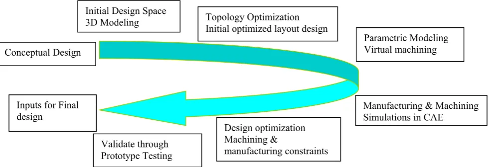
Through cutting simulations, a designer can predict the post machining distortions, and thereby decide about the optimal clamping and cutting sequence of machining operations. Manufacturing simulations at the design stage result in reducing unnecessary efforts which mean cost efficient products with enhanced reliability and quality. This also helps in avoiding design modifications due to machining and manufacturing constraints which are viewed afterwards during the actual prototype testing in conventional design approach. In this paper, nonparametric topology optimization is applied to a commercial aircraft vertical stabilizer component. The methodology adapted is described in Fig. 1.
The first step is the development of a 3D model of initial design space, which defines the inner and outer boundaries within which material has to be arranged and optimized. Volumes and features that need not to optimize are clearly defined like predefined holes, fixed parts, and supports of the component. Depending on the complexity of model, this can also be done in CAD software and then imported in CAE system. The next step is the mesh generation and change of attributes of elements of regions not to be optimized. Specifications needed for optimization process like objective function, constraints etc are defined, and model is solved for topology optimization results. These results give a load compatible shape, consisting of a set of connected elements. The resulting model seems to be a rough nongeometry based design which is refined and smoothen by different approaches and then drawn back in CAD software. The model is also refined for various manufacturing and machining restrictions like minimum thickness requirements, aesthetic features, nonmachineable areas, undercuts etc. Virtual machining of this model is then carried in a virtual machining module to verify the machining and manufacturing possibility of new design.
To optimal design the component, machining and post machining problems are also studied using manufacturing process simulations. Effects of post machining distortions and optimal cutting sequence are also determined through cutting simulation technique in ANSYS software. A sequential coupled Field analysis is performed to develop an initial residual stress field in the model.
Initial Design Space
3D Modeling Topology Optimization Initial optimized layout design
Parametric Modeling Virtual machining
Manufacturing & Machining Simulations in CAE
Validate through Prototype Testing Inputs for Final
design
Conceptual Design
Design optimization Machining &
[image:2.595.52.544.569.737.2]manufacturing constraints
This is to account for the residual stresses developed in the actual material due to heat treatment processes. Simulation results are verified through actual prototype testing before final design. This integrated design approach is applied on a commercial aircraft vertical stabilizer component as shown in Fig. 2. Loads on the vertical tail are mainly caused by the rudder deflection, aileron deflection, lateral gust and asymmetric engine thrust. The resultant pressure distribution over the skin causes direct loads, bending, and shears in the components attached to the skin. Suitable loads and constraints are applied to the initial design space to withstand the critical combination of all these loads as shown in Fig. 2.
Fig. 2. Vertical fin component
II. 3DMODELING AND TOPOLOGY OPTIMIZATION
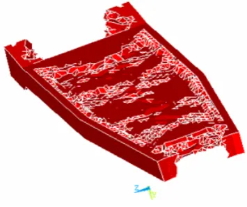
A 3D model prepared in ANSYS is shown in Fig. 3, which represents the initial design space of the actual component of an airplane. This initial design space is developed as per the actual dimensions of outer boundaries. Material of component is AL7075T-6. Considering aerodynamic requirements, volumes attached directly to the skins are selected as nonoptimized regions but only the load carrying structures. The whole design space is meshed into 44866 numbers of elements with type of element Solid95. Attributes of all the elements in regions defined as nonoptimzed are modified as type 2 elements. Areas adjacent with the skins are constraint in horizontal plane only. Initially, a load of 5 MPa is applied on two side surface areas as a single load case. Optimization parameters are defined as single compliance and 50 % volume reduction to the initial volume. Results of the topology optimization converged after 25 iterations that are shown in Fig. 4.
The optimization results shown in Fig. 4 give a new design proposal with internal ribs as linking walls. These results give a lightweight structure that can withstand the applied loads with maximum stiffness. These are then refined to form geometry based design. Results are shown in Fig. 5 for 50% volume reduction. Fig. 5 shows elements selected by results having a density value of one only. Results of the topology optimization give a freedom to remove volume from two extreme ends in length direction. This is closer to the actual part design in which a number of holes are made for providing passage for electrical, hydraulic and pressure sensing devices.
[image:3.595.53.287.205.365.2]Fig. 3. 3D model for Topology Optimization
[image:3.595.321.542.264.364.2]Fig. 4. Topology optimization results (Total density plot)
Fig. 5. Topology optimization results (Elements with density value one only)
Results of the topology optimization are refined and smoothened in CATIA software to convert into a geometry-based design. Accurate nodes are selected for geometric measurements first by selecting all nodes at position y=0 in thickness direction, and taking origin x,y,z as a reference point. In TOSCA optimization software, this step is accomplished with TOSCA.smooth module having an ANSYS interface [9]. Model is modified for minimal feature size requirements and tool nonapproachable areas and then virtually machined. The optimized model is shown in Fig. 6.
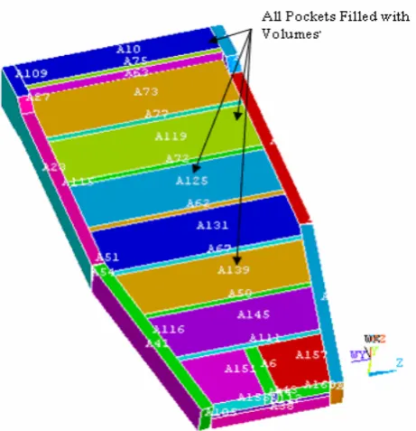
[image:3.595.337.515.396.545.2]simulation process, all the empty pockets of the initially optimized 3D model are filled with pocket volumes. Volumes of 12.5 mm thickness layer each on the top and bottom faces are created to perform virtually the facing operations. These processes are shown in Fig. 7 and 8. Component distortions during and after machining process are mainly caused by the redistribution of initial residual stresses developed in the material during heat treatment and stress relieving operations. For this purpose, a Sequential Coupled Field analysis is performed to develop a residual stress field in the model.
Fig. 6. Geometry based design of topology optimization (Front and Bottom sides)
Fig. 7. Model preparation for machining simulations Value of residual stresses range about + 30 MPa for
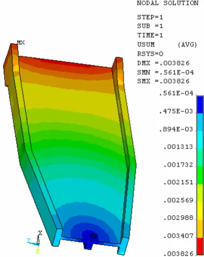
aluminium alloys on which a pre stretching operation is performed for stress relieving purpose [10]. After defining the material data, 3D model is meshed with thermal Solid70 type of element into 60320 numbers of elements. To simulate the heat treatment process and to obtain the initial temperature distribution both thermal and convection loads are applied. A temperature of 100 °C is applied to all the nodes with an additional temperature of 20°C on all the external surface areas. Convection load is also applied simultaneously on all external surface areas. The model is solved and an initial temperature distribution is obtained. To obtain the residual stress filed, structural analysis is performed in continuation of thermal analysis. Elements type
is switched from thermal to structural, all the previously applied thermal loads are removed, and new structural loads are applied.
[image:4.595.309.544.188.424.2]A symmetry boundary condition is applied on all side surface areas and bottom surface area only. This time, thermal loads are applied by browsing through the path to result file (.rth) obtained previously in thermal analysis. The model is solved and a nonsymmetric residual stress field is obtained. Stresses measured in thickness direction and plotted with curve estimation in SPSS statistics software are shown in Fig. 9.
Fig. 8. Model preparation for machining simulations Stresses lie within the range of + 30 MPa in the thickness direction, which means simulation methodology adopted here give closer results to the published data [10]. After developing initial residual stresses, machining simulations are performed using element deactivation technique. This technique is used because conventional contact analysis approaches lack to simulate large machining especially when complete machining effects are to be analyzed [11]. The model is constrained by constraining all D.O.Fs of two side areas.
All the elements in the top layer volume are selected, and deactivated by using element Birth/Death feature in ANSYS. Similarly, elements of all the pockets of first side are deactivated pocket by pocket, like machining simulation of 4th pocket, which is shown in Fig. 10(a). The similar
[image:4.595.54.285.357.596.2]Fig. 9. Residual Stress development
Fig. 10(a). Machining simulations (4th Pocket machining)
Fig. 11. Virtual machining of actual part (CATIA) Distortion range measured on the actual part after machining is presented in table I.
Table I Machining dimensional inaccuracy Dimensional inaccuracy in Direction Millimetre
Longitudinal 1.5 Transverse 1.44 Thickness 0.98
Fig. 10(b). Bottom side machining simulation IV. CONCLUSIONS
Optimization driven design is compared to the actual part design that is being manufactured for the aircraft as shown in Figs. 2 and 11. It is inferred that under the same loading conditions, constraints and intended design purposes, topology optimization results in better and more reliable design. A designer can produce the best optimized design without much dependency of his experience and previous design options and practices. In this research, some features which obtained in the topology optimization results are omitted in the analysis model because these do not affect the cutting simulations largely and model can be simplified. For example material is shown removed from two ends in actual topology optimization results but included in the analysis model for simplification. However, topology optimization results are valid because in the actual part this can be compared with the number of holes made for passage of electric and hydraulic instruments. This can be incorporated at the final design stage.
By comparing the machining simulations with the actual ones, it is deduced that the methodology adopted to design the component considering machining and manufacturing early at the design stage is very useful for robust and reliable design options. Contradictions of simulated results with the actual ones are because of approximations and assumptions made in the simulations and neglecting some small scale simulations for example, tool deflections and wear effects in the simulations etc [12]. However, at the early design stage, large scale simulations as performed in this research is very effective as the designer can considers and takes remedies of problems like controlling post machining distortions, optimal cutting sequence etc. It is inferred that application of topology optimization and manufacturing simulations in the product design and development process reduce efforts, times, and result in better products.
Thickness (mm)
Residual Stress
(MP
[image:5.595.325.532.52.312.2]Table II Machining simulations result
Machining Zone Average Sum X (+ve) X (-ve) Y (+ve) Y (-ve) Z (+ve) Z (-ve)
Top Layer 2.019 1.85 -0.33 0.714 -0.379 0.9072 -1.42
1st Pocket 2.023 1.84 -0.307 0.714 -0.379 0.868 -0.874
2nd Pocket 1.672 1.433 -0.307 0.714 -0.379 0.862 -0.863
3rd Pocket 1.568 1.312 -0.307 0.714 -0.379 0.853 -0.861
4th Pocket 1.49 1.221 -0.307 0.714 -0.379 0.854 -0.858
5th Pocket 1.387 1.113 -0.307 0.714 -0.379 0.826 -0.82
6th Pocket 1.155 0.89 -0.307 0.714 -0.379 0.723 -0.72
7th Pocket 0.716 0.577 -0.307 0.714 -0.379 0.549 -0.49
8th Pocket 0.716 0.191 -0.307 0.714 -0.379 0.549 -0.49
Unclamped (1st Side Machined) 4.506 2.62 -2.95 1.901 -3.45 1.442 -1.43
Bottom 1st Layer 4.33 4.162 -0.357 0.18 -1.63 1.315 -1.273
Bottom 2nd Layer 3.826 3.809 -0.162 0.514 -0.554 1.56 -1.538
Final Stage 2.308 1.9 -2.177 0.384 -0.533 1.65 -1.635
13.00 12.00 11.00 10.00 9.00 8.00 7.00 6.00 5.00 4.00 3.00 2.00 1.00
Machining Zone
4.00
2.00
0.00
-2.00
-4.00
Disp
lace
men
t (m
m) Z -ve (Transverse direction)
Z +ve (Transverse direction) Y-ve (Thickness direction) Y+ve (Thickness direction) X -ve (Longitudnal direction) X +ve (Longitudnal direction)
Note: 1 (Top Layer machined), 2 (1st Pocket machined), 3 (2nd Pocket machined),4(3rd Pocket machined), 5 (4th Pocket machined), 6 (5th Pocket machined), 7 (6th Pocket machined), 8 (7th Pocket machined), 9 (8th Pocket machined), 10 (Part Unclamped), 11 (2nd Side 1st Layer machined), 12 (2nd Side 2nd Layer machined), 13 (Final Stage)
[image:6.595.85.469.140.515.2]Machining Simulations Results
Fig. 12 Machining simulations distortion trend REFERENCES
[1] M. P. Bendsoe., O. Sigmund, Topology Optimization, Theory Methods and applications, Springer Verlag ISBN 3-540-48992-1, 2003, pp 1-47 [2] S. Grihon, L. Krog, K. Hertel, “A380 Weight Savings Using Numerical Structural Optimization”, proceedings of 20TH AAAF Colloquium, Material for Aerospace Applications, Paris, Nov 24-26, 2004
[3] Lars Krog, Alastair Tucker, Gerrit Rollema, “Application of topology, sizing and shape optimization methods to optimal design of aircraft components”, Airbus UK Ltd, Altair Engineering Ltd., 2002
[4] L. Krog, A. Tucker, Martin Kemp, Richard Boyd, “Topology Optimization of Aircraft Wing Box Ribs”, 2004, [10th AIAA/ISSMO Multidisciplinary Analysis and Optimization Conference]
[5] Gerd Schuhmacher, Martin Stettner, Rainer Zotemantel, O. Owen. Leary, Markus Wagner, “Optimization assisted structural design of a new military transport aircraft”, EADS Military Aircraft, Munich, Germany, 2004, [10th AIAA/ISSMO Multidisciplinary Analysis and Optimization Conference, Albany, New York]
[6] M. P. Bendsoe, E. Lund, N. Olhoff, O. Sigmund, “Topology optimization–broadening the areas of application”, Control and Cybernetics, 2005,Vol. 34, No. 1, pp. 7-35.
[7] M. P. Bendsoe and N. Kikuchi, “Generating optimal topologies in structural design using a homogenization method”, Comp. Meths. Appl. Mech. Engrg, 1988, 71, pp 197–224.
[8] ANSYS V10 Help, Design optimization, Ch 20
[9] Thorsten Schmidt Heidenreich and A. G Harbeck, Molln, Deutschland, “Faster to superior casting components by employment of the topology optimisation with the supplier” NAFEMS Seminar, Optimization in structural mechanics, April 27-28, 2005, Wiesbaden, Germany
[10] ASM Handbook, Heat Treating, Vol. 04, ISBN 0-87170-379-3, 1991,
pp 1905-1949
[11] Marcus Sandberg, Tobias Larsson, Peter Astrom and Mats Nasstrom, “A design tool integrating cad and virtual manufacturing for distortion assessment”, 2005, [International conference on engineering design iced 05]
![Fig. 12 Machining simulations distortion trend [6] M. P. Bendsoe, E. Lund, N. Olhoff, O](https://thumb-us.123doks.com/thumbv2/123dok_us/1330351.663990/6.595.85.469.140.515/fig-machining-simulations-distortion-trend-bendsoe-lund-olhoff.webp)