Abstract—This paper proposes a new auto-exposure and auto white-balance algorithm that can accurately detect high-contrast lighting conditions and improve the dynamic range of output images for a camera system. The proposed method calculates the difference between the mean value and the median value of the brightness level of captured images to estimate lighting conditions. After that, a multiple exposure mechanism is carried out to improve the details of output pictures. Finally, a simple auto white-balance algorithm is performed. Simulation results show that the system works well with CMOS sensors used in mobile phones and surveillance cameras. Besides, the proposed algorithm is fast and simple and therefore can be fitted in most CMOS platforms that have limited capabilities.
Index Terms—auto exposure, auto white-balance, mean value, median value, multiple exposure.
I. INTRODUCTION
Auto-exposure (AE) and auto white-balance (AWB) have become two major functions of digital camera systems. Many platforms that provide both AE and AWB controls have been proposed to accommodate various shooting conditions and these two functions can help improve the overall system performance.
Many AE algorithms have been developed [1]-[4] to deal with high-contrast lighting conditions. However, most of these algorithms have some drawbacks on either their accuracy or complexity which may prevent them from being applicable to low-capacity camera platforms such as those employing CMOS technologies.
According to [1], it is difficult to discriminate back-lit conditions from front-lit conditions using histogram methods [2], [3]. Further simulations in this paper shows that the tables and criteria used to estimate lighting conditions are confusing and not consistent.
Other algorithms [3], [4] used fixed-window segmentation methods to estimate the brightness and lighting conditions. Besides, these papers and [1] only considered images with only one main object. Therefore, these algorithms are not flexible and do not work well with other images in which a main object does not exist.
In [5], multiple exposure methods were presented to
Quoc Kien Vuong, Se-Hwan Yun, and Suki Kim are with Dept. of Electronics and Computer Engineering, Korea University, 5-ga Anam-dong Seongbuk-gu, Seoul 136-713, Repbulic of Korea (phone: 82-2-927-2398; fax: 82-2-927-1582; e-mail: quockienvuong@ korea.ac.kr).
improve the dynamic range of output pictures. Simulation results showed that its algorithm might easily lead to color inconsistency and bad chromatic transitions.
For AWB, the color gains are controlled such that objects which appear white in human eyes are rendered white in the output image. When a white object is illuminated under a low color temperature, it will appear reddish in the captured image. Similarly, it will appear blueish under a high color temperature. Each AWB algorithm consists of two steps. The first step is illumination estimation, and the second step is image compensation.
According to [6], there are two categories of AWB: global AWB algorithms and local AWB algorithms. Global AWB methods such as gray world assumption, [7], [8] may not work well if the picture is dominated by just a few colors. Local AWB methods [9], [10] depend on the existence of white objects or human faces in captured images.
This paper introduces a new approach to control AE which can be used to determine the degree of contrast lighting employing a simple and quick method which is presented in Section II. Section III describes how to decide if the condition is normal lit, excessive back lit or just a condition with a high dynamic range. Then the algorithm uses a simple multiple exposure mechanism to improve the dynamic range of the output image so that more details can be revealed. In Section IV, a refined and simple AWB method is presented based on the idea of gray color points in [6]. Section V describes simulation results. Finally, conclusions are given in Section VI.
II. AE ALGORITHM FOR LIGHTING-CONDITION DETECTION Lighting conditions can be classified as normal lit, excessive back lit or high contrast. To determine the degree of lighting conditions, the proposed method compares the mean value and the median value of the brightness level of the whole image.
The mean brightness level Blmean is the average brightness
level of the whole image. On the other hand, the median value Blmed is the value of the middle item in a sorted array of
brightness levels of all pixels in the image.
Most platforms employing CMOS image sensors (CIS) provide output images in the RGB format. The green component mostly contributes to the luminance of an image. Therefore, to reduce computational complexity, the proposed system uses the green (G) component as the luminance of an image and all steps are performed based on this component.
A New Auto Exposure and Auto White-Balance
Algorithm to Detect High Dynamic Range
Conditions Using CMOS Technology
In an image possessing normal lit condition, the difference DL between Blmean and Blmed is not significant, especially in
the cases of normal and under exposure. However, when an image is captured in back-lit or high-contrast lighting conditions and in cases of under and normal exposure, Blmean
is very different from Blmed. In the case of over exposure, the
difference varies unpredictably; nevertheless, in normal- and under-exposed images that possess back-lit condition, Blmean
is always larger than Blmed and the difference trend is stable.
Fig. 1 shows the difference between these two values for various cases. Note that Dthres is the threshold of the
difference value.
Blmean, Blmed, DL and Dthres are used to enhance the proposed
modified AE algorithm. According to [1] and [11], the relationship between the luminance value and the exposure factors can be expressed as
2
( /#)
Bl k L G T= × × × × F − . (1)
where Bl is the brightness level of the captured image, k is a constant, L is the luminance of the ambient light, G is the gain of the automatic gain control, F/# is an aperture value, and T is the integration time.
Let Bln and Blopt denote the brightness levels of the current
frame and the frame taken with optimal exposure time. For a certain scene and when both frames are taken continuously within a very short time, L and G remain almost the same. For most cell phones and surveillance cameras employing CMOS technologies, the aperture is fixed at its maximum value, thus F/# is constant. The exposure functions (1) for the current frame and the frame taken with optimal exposure time are:
2
( /#)
n n
Bl = × × × ×k L G T F − . (2)
2
( /#)
opt opt
Bl k L G T F −
= × × × × . (3)
By dividing (2) by (3), the relationship between Bln and
Blopt can be expressed as
[Bln/Blopt] [ /= T Tn opt]. (4)
2 2 2 2
log Bln−log Blopt=log Tn−log Topt. (5)
2 2 2 2
log Topt =log Tn−log Bln+log Blopt. (6) The proposed algorithm uses Blmean to control AE based on
the idea of mid-tone in an iterative way. However, unlike [1], in this paper, the optimal brightness level is not fixed. Blopt
may be changed according to the lighting conditions. Besides, since the camera response is not totally linear, the actual values in each condition are obtained by performing a series of experiments.
Let norm opt
Bl denote the optimal brightness level in the case of normal-lit conditions with low exposure time,
bkdr opt
Bl denote the optimal value in the case of back lighting or high contrast lighting conditions with low exposure time, and let over
opt
Bl denote the optimal value in the case of over exposure.
[image:2.595.314.530.53.313.2] [image:2.595.315.533.59.587.2] [image:2.595.346.527.348.586.2]In real implementation, (6) is convenient for data to be stored in look-up tables (LUT). The mid-tone range Blmt is
[100, 130]. After capturing the first frame, the value of Blmean
is calculated and is used to decide the value of Blopt as
described in Fig. 2. After that, the optimal exposure time is obtained using (6).
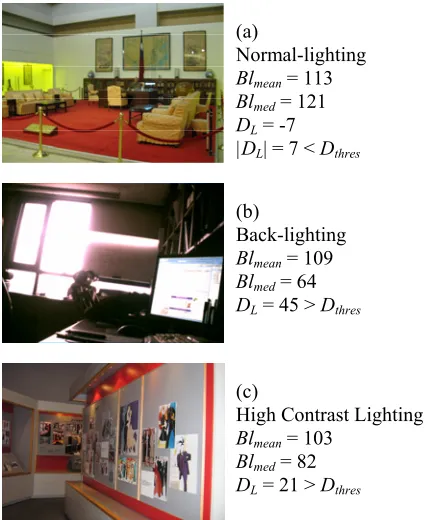
Figure 1. Blmean, Blmed, and DL in different lighting
conditions
+
+
+
-Blmean
Blmean < min
of Blmt ? Blmean in Blmt ?
DL< Dthres?
Blopt = Bloptbkdr
Blopt = Bloptnorm Blopt = Bloptover
Next stage
Figure 2. Deciding value for Blopt
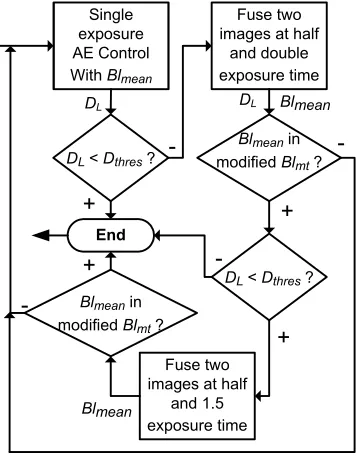
III. MULTIPLE EXPOSURES
After controlling the exposure time so that Blmean falls into
the mid-tone range, the value of Blmed at that optimal
exposure level is calculated. Then DL is obtained as the
difference between Blmean and Blmed.
At this stage, a multiple exposure algorithm described in Fig. 3 is employed using two successive frames taken with two different exposure times.
The two frames are fused together as follows: ( , ) ( lo( , ) hi( , )) / 2
X X X
F x y = F x y +F x y . (7)
where FX(x, y) is the color value of the pixel (x, y), X is either
R, G, or B component, lo is low exposure and hi is high exposure.
(c)
High Contrast Lighting Blmean = 103
Blmed = 82
DL = 21 > Dthres
(b)
Back-lighting Blmean = 109
Blmed = 64
DL = 45 > Dthres
(a)
Normal-lighting Blmean = 113
Blmed = 121
DL = -7
Single exposure AE Control With Blmean
DL < Dthres ?
Fuse two images at half
and double exposure time
Blmean in
modified Blmt ?
DL < Dthres?
Fuse two images at half
and 1.5 exposure time Blmean in
modified Blmt?
End DL
+
+ +
+
-
-DL Blmean
Blmean
Figure 3. Multiple exposure algorithm
The multiple exposure mechanism can bring more details to dark areas and over-exposed areas. The frame taken with a lower exposure time provides details; on the other hand, the frame taken with a higher exposure time brightens the fused image.
After image fusion, the updated Blmean is validated using a
modified mid-tone range [90,130].
IV. IMLEMENTATION OF AWB
An AWB algorithm consists of two steps: color temperature estimation, and color channels adjustments. Of the above two steps, the estimation of color temperature is more important and it decides the overall accuracy of the whole AWB mechanism. The algorithm in [6] selects out gray color points from an image to judge the illumination condition. Gray color points can be a white object, a shadow, a black object and so on. Each gray color point has a little deviation from the color gray under different color temperature light sources.
In [6], the YUV coordinate is used, where Y is the luminance component, and U and V are two chrominance components. Gray color points can be extracted using the following criterion:
( )
( , , ) U V
F Y U V T
Y +
= < . (8)
where T is a threshold value which is far less than 1, and ( , , )
F Y U V is defined as
( )
( , , ) ( )
in low color temperature 1 0.299
in high color temperature 1 0.114
R
R B
B
U V
U V
F Y U V
Y Y Y
K K K
K
+
= + =
+ =
+
⎧
⎪
⎨
⎪
⎩
(9)
where KR and KB are deviation factors of red (R) and blue (B)
components in the RGB format. KR can be calculated by
' (1 R)
R = +K R, where R and R’ are the R components of gray color points in canonical light and non-canonical light, respectively. Similarly, KB can be calculated by
" (1 B)
B = +K B, where B and B” are the B components of gray color points in canonical light and non-canonical light, respectively.
In this paper, the proposed system uses the G component to control the exposure time. Therefore, in order to reduce computational complexity, after the AE control, the system will continue to use the G component as the luminance for AWB control and only adjust the R and B gains.
The algorithm in [6] is modified and the proposed AWB system uses the following function and criterion to extract gray color points:
( )
( , , ) ( R B ) R B
F R G B
G G G
+
= + = . (10)
( )
( , , ) R B
F R G B T
G +
= < . (11)
where T is the threshold value which is far less than 1. However, in the case of pixels whose G value is 0, T is set to 1, and G is set to 1 in (10).
Each pixel whose value of ( , , )F R G B satisfies (11) is accumulated in Ω, where Ω is the set of gray color points.
Let RΩ , BΩ , GΩ and denote the average of R, B and G
components of Ω. These values are used to estimate the illumination condition and to control the R and B gains in an iterative way. Let RGΩdenote the absolute difference value
between RΩ andGΩ , and let BGΩ denote the absolute
difference value between BΩ and GΩ . These values are
calculated as:
RGΩ = RΩ−GΩ . (12)
BGΩ = BΩ−GΩ . (13)
If RGΩ−BGΩ
≤
DAWBthres , where DAWBthres is a threshold value, the AWB control is done; otherwise, ifRGΩ>BGΩ, the R gain needs to be adjusted. Similarly, if
BGΩ>RGΩ, the B gain needs to be adjusted.
[image:3.595.69.249.51.280.2]V. SIMULATIONS
Fig. 4 describes the simplified functional block digram of the proposed system with AE and AWB functions. The output data of the auto focus (AF) and interpolation block are fed to the AE block. Note that the AF capability is optional. Most CMOS platforms are not equiped with AF function. In the AE block, after multiple exposure controlling, output data are sent to the AWB block.
Simulations were carried out using a simple platform employing CMOS image sensors (CIS) with AE parameter values as follows
Dthres = 20; log2Bloptnorm = 6.8 log2 bkdr
opt
Bl = 7; log2 over opt
Sensor Block
Interpolation and Auto Focus Block
AWB Block AE Block
Output Image (RGB format)
RGB format
R & B
gains Exposure time
Focal control (optional)
Figure 4. Simplified functional block diagram of the proposed camera system
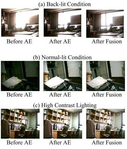
Figure 5. Simulations with AE algorithm
TABLE I. EVALUATION OF BACK-LIT CONDITIONS After AE After Fusion Starting
Values Bln Bln
Scene
Bln DL
Times D
L Y G DL Y G
(1) 156 8 1 40 118 116 27 123 122 (2) 130 27 1 42 107 104 29 115 112 (3) 160 -6 1 39 121 121 22 121 120 (4) 173 -78 2 39 111 111 24 114 114 (5) 87 49 1 45 115 114 31 119 117
TABLE II. EVALUATION OF HDR CONDITIONS
After AE After Fusion Starting
Values Bln Bln
Scene
Bln DL
Times D
L Y G DL Y G
(1) 84 22 2 21 120 120 12 109 109 (2) 22 13 2 32 106 100 19 112 105 (3) 77 29 2 25 115 114 13 107 106 (4) 169 -33 2 30 117 116 19 111 111 *(5) 37 15 1 45 121 112
[image:4.595.302.549.55.169.2]*night scene taken with the system’s maximum exposure value; thus no fusion was carried out after AE.
TABLE III. EVALUATION OF NORMAL-LIT CONDITIONS After AE After Fusion Starting
Values Bln Bln
Scene
Bln DL
Times D
L Y G DL Y G
(1) 79 -3 1 -11 117 115 -14 110 109 (2) 82 14 1 14 105 104 8 99 99 (3) 8 3 3 15 109 106 8 99 98 (4) 40 11 1 15 107 111 9 101 104
*(5) 3 1 1 0 42 39
*night scene taken with the system’s maximum exposure value.
Simulation results show that the proposed AE algorithm can detect lighting conditions accurately and does not require much computation. Furthermore, the algorithm is independent from the position of the light source and can work well with images with or without a main object.
Because of the non-linear characteristics of CMOS sensors, sometimes it requires that the AE algorithm be iterated more than once since the first calculated exposure value does not return a value in the range of Blmean in Blmt.
Therefore the overall AE mechanism may include more than one adjusting time.
[image:4.595.63.278.221.473.2]Tables I-III demonstrate simulation results for all cases of lighting conditions. Both Y channel (luminance component in the YCbCr format) and G channel are observed. Simulation results show that G component can be used as the luminance of an image without any significant difference. Furthermore, the lighting condition of each scene is correctly detected as its real condition. In most cases, the number of times the AE mechanism is iterated is less than two. This indicates that the proposed algorithm provides a high accuracy rate and fastens the overall performance.
Table I describes simulation results of back-lit conditions. The values of DL after AE controlling and after fusion show
that fused images provide more details than un-fused ones. This ability is very useful for camera systems that employ CMOS image sensors with limited dynamic range.
In Table II, scenes possessing high dynamic range (HDR) conditions are evaluated. After AE controlling, the multiple exposure mechanism is carried out twice. The values of DL
also indicate that fused images provide more details than un-fused ones.
Table III describes simulation results of images taken in normal-lit conditions. The simulation also shows further values of these pictures after fusing using two images taken at half and 1.5 times the optimal exposure time. These experiment results indicate that this multiple exposure mechanism can also provide more details in output images for surveillance systems.
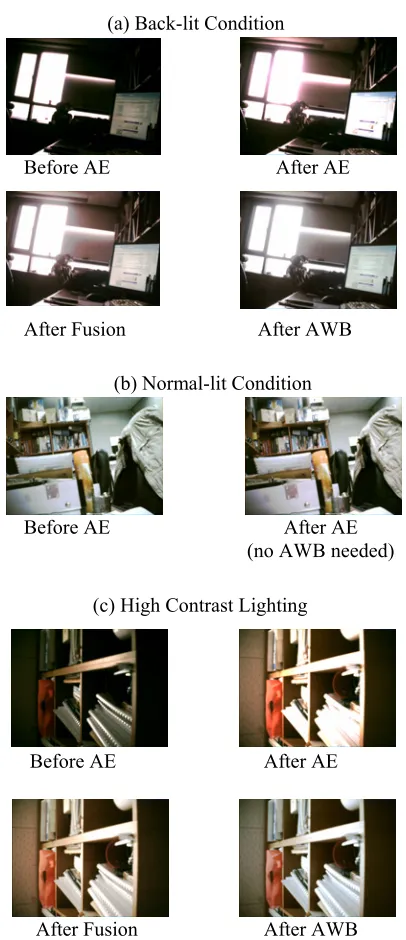
For AWB control, the value of DAWBthresis set to 1. In [6], there are three values for T: 0.97, 0.1321, and 0.2753. However, due to limited capabilities and accuracy of CMOS platforms, the threshold value T in the proposed system is set to 0.28. Fig. 6 demonstrates the evaluation of the whole system including both AE and AWB functions.
Before AE After AE After Fusion (a) Back-lit Condition
(b) Normal-lit Condition
Before AE After AE After Fusion (c) High Contrast Lighting
Figure 6. Simulations with AE and AWB
VI. CONCLUSION
A new AE algorithm with lighting condition detecting capability has been introduced. The proposed algorithm can quickly estimate an appropriate exposure value after a small number of frames. It can also improve the accuracy and enhance the details of output images.
The proposed AWB method, which is performed after AE control, is a simple local AWB algorithm. This algorithm provides high accuracy and flexibility owing to the omnipresence of gray color points.
Using the new mechanism to detect light conditions, the system is flexible and can work well with most images without being affected by the positions of light sources and main objects. Since the algorithm is not computationally complicated, it can be fitted in most CMOS platforms that have limited capabilities such as cell phones and/or surveillance cameras.
REFERENCES
[1] J. Y. Liang, Y. J. Qin, and Z. L. Hong, “An auto-exposure algorithm for detecting high contrast lighting conditions,” Proc. of the 7th Int. Conf.
on ASIC, Guilin, Peoples R. China, vols. 1 and 2, pp. 725-728, Oct.
2007.
[2] S. Shimizu, T. Kondo, T.Kohashi, M. Tsuruta, and T. Komuro, “A new algorithm for exposure control based on fuzzy logic for video cameras,” IEEE Trans. Consum. Electron., vol. 38, pp. 617-623, Aug. 1992.
[3] M. Murakami, and N. Honda, “An exposure control system of video cameras based on fuzzy logic using color information,” Proc. of the 5th
IEEE Int. Conf. on Fuzzy Systems, Los Angeles, vols 1-3, pp.
2181-2187, Sep. 1996.
[4] J. S. Lee, Y. Y. Jung, B. S. Kim, and S. J. Ko, “An advanced video camera system with robust AF, AE, and AWB control,” IEEE Trans.
Consum. Electron., vol. 47, pp. 694-699, Aug. 2001.
[5] W. C. Kao, C. C. Hsu, C. C. Kao, and S. H. Chen, "Adaptive exposure control and real-time image fusion for surveillance systems," Proc. of
IEEE Int. Symposium on Circuits and Systems, Kos, Greece, vol. 1-11,
pp. 935-938, May 2006.
[6] J. Y. Huo, Y. L. Chang, J. Wang, and X. X. Wei, “Robust automatic white balance algorithm using gray color points in images,” IEEE
Trans. Consum. Electron., vol. 52, pp. 541-546, May 2006.
[7] Y. Kim, J. S. Lee, A. W. Morales, and S. J. Ko, “A video camera system with enhanced zoom tracking and auto white balance,” IEEE Trans.
Consum. Electron., vol. 48, pp. 428-434, Aug. 2002.
[8] Y. C. Liu, W. H. Chan, and Y. Q. Chen, “Automatic white balance for digital still camera,” IEEE Trans. Consum. Electron., vol. 41, pp. 460-466, Aug. 1995.
[9] N. Nakano, R. Nishimura, H. Sai, A. Nishizawa, and H. Komatsu, “Digital still camera system for megapixel CCD,” IEEE Trans.
Consum. Electron., vol. 44, pp. 581-586, Aug. 1998.
[10] B. Hu, Q. Lin, X. L. Kang, and G. M. Chen, “A new algorithm for automatic white balance with priori,” IEEE Asia-Pacific Conf. on
Circuits and Systems, Tianjin, Peoples R. China, pp. 109-112, Dec.
2000.
[11] T. Kuno, H. Sugiura, and M. Atoka, “A new automatic exposure system for digital still cameras,” IEEE Trans. Consum. Electron., vol. 44, pp. 192-199, Feb. 1998.
[12] N. Sampat, S. Venkataraman, T. Yeh, and R. L. Kremens, “System implications of implementing auto-exposure on consumer digital cameras,” Proc. of SPIE Conf. on Sensors, Cameras, and Applications
for Digital Photography, San Jose, vol. 3650, pp. 100-107, Jan. 1999.
[13] M. H. Cho, S. G. Lee, and B. D. Nam, “The fast auto-exposure algorithm based on numerical analysis,” Proc. of SPIE Conf. on
Sensors, Cameras, and Applications for Digital Photography, San
Jose, vol. 3650, pp. 93-99, Jan. 1999.
[14] T. Haruki, and K. Kikuchi, “Video camera system using fuzzy logic,”
IEEE Trans. Consum. Electron., vol. 38, pp. 624-634, Aug. 1992.
(a) Back-lit Condition
Before AE After AE
After Fusion After AWB
(b) Normal-lit Condition
Before AE After AE
(no AWB needed)
After AE
After Fusion
(c) High Contrast Lighting
Before AE