Abstract—It is still a serious challenge for structural engineer to effectively reduce the wind responses of tall and super tall buildings to further improve these structural safeties. To solve the problem of pounding occurs between the mega-frame and substructures, as well as the large span of the mega beams of mega-sub structure (MSS), in this paper a new kind of structural configuration, named mega-sub controlled structure (MSCS), is presented, which is constructed by applying the structural control principle into structural configuration itself, to form a new structure with obvious response self-control ability, instead of employing the conventional method. Dynamic equation and method to assembling parameter matrixes for the meg-sub-controlled structure subjected to random wind loads are presented based on a realistic analytical model of the complete mega-structural system. According to the peculiarity and deformation of the systems, a more realistic analytical model of this structure subjected to random wind loads is presented, in which the substructures are treated as multi-degree-of-freedom (MDOF) system, the dominant vibration mode for the mega-frame is controlled by bending deformation; shear deformation is the governing mode for the less slender substructures. The displacement, acceleration responses and response spectrum are then determined for both the MSCS and its conventional structure counterpart.
Moreover, the additional damping ratio
ρ
c , additionalcolumns stiffness ratio
R
kare defined and the influence of the two parameters is discussed. The study illustrates that the improved MSCS can effectively reduce the displacement and acceleration responses, as well as ameliorates the control effectiveness of tall/super-tall mega-systems. This lay a foundation for further studying seismic performance and design of steel mega-frame structures.Index Terms—control effectiveness, mega-sub controlled structure, structural characteristics, stationary random process, wind response
I. INTRODUCTION
Nowadays, more and higher requirement about building figuration, function and space is put forward along with the development of society and the construction of city. An effective approach is to create a new-style and high-performance structure system in which can actualize controlling measure easily and accord with control principle
Manuscript received July 25, 2008. This work was supported in part by Science and Technology Fund of NWPU Under Grant No. M450211.
Xiangjun Qin is with the Department of Civil Engineering, Northwestern Polytechnical University, Xi’an, China, postal code: 710072. Tel: (+86)13474537497; e-mail:[email protected].
Xun’an Zhang is with the Department of Civil Engineering, Northwestern Polytechnical University, Xi’an, China, 710072. E-mail: [email protected].
[1]. Mega-sub structure (MSS) has been used in construction of many tall buildings and super tall buildings, e.g., the Bank of China at Hong Kong and Tokyo City Hall at Japan, for its excellent integral, multifunction and low cost. The MSS consists of two major components: a mega-frame, which is the main structural frame in the building, and several substructures, each containing many storeys that are used for commercial and/or residential purposes. In this configuration the substructures are rigidly connected to the mega-frame, as shown in Fig.1. The main advantage of MSS is that the system has a stronger ability to resist the horizontal forces acted by wind and earthquake, and could provide the chance to design the substructures into different ingenious forms, such as mega-sub controlled structure(MSCS) proposed in this paper..
Mega-sub controlled structure(MSCS) is first proposed by Feng and Mita, they proposed the idea that the substructure of mega-sub structure(MSS) could be designed as mass of frequency modulation to suppress the vibration of the entire building [2]. The results showed that the substructures of this configuration have a strong tuned mass damper (TMD) function Chai and Feng subsequently improved this configuration and presented a primal MSCS, in which the substructure was seated on the mega-beam-storey of mega-sub structure [3]. This is a breakthrough of idea to conventional MSS. However, there still exists some design difficulties of all these early studies that need to be addressed before the proposed structural configurations can be applied to practice. First, these analyses were based on the assumption that each substructure, which is the multi-degree-of-freedom (MDOF) system, was treated as only one concentrated mass. Second, the displacement responses of substructure may be so large that pounding could occur between the mega-frame and the substructures. Also, the mega beams and the corresponding mega-beam-storey elements that are needed to support the heavy, flexible substructures are overly large-span structural elements. These shortcomings must be considered to improve this type of tall/super tall buildings configuration.
In this paper, a new mega-sub controlled structural configuration, that eliminates the above noted deficiencies, is proposed as illustrated in Fig 2, the substructures are designed as isolated substructures, whose function is similar to that of the conventional tuned mass damper system in principle but with more advantageous than it. Dampers (or named as additional dampers) are installed between the mega-frame and its substructures. This arrangement allows
Vibration Controlling Characteristics of a New
Improved Mega-Sub Controlled Structure
Subjected to Random Wind Loads
the substructures to act as a huge mass-damper system, which eliminates pounding between the mega-frame and its substructures. Unlike the completely flexible arrangement of the substructures initially proposed by Chai and Feng[3], additional columns are introduced between the mega-frame and the top-level of the substructures to eliminate the shortcomings associated with the previously noted, excessively large-span mega-beams resulting from the configuration arrangement.
For analyzing this structure, a more realistic analytical model is proposed. The purpose of the present paper is to examine the dynamic behavior and the response control effectiveness of this new proposed MSCS under rand wind loads.
II. THE DYNAMIC EQUATION OF MEGA-SUB CONTROLLED
STRUCTURE SUBJECTEDTO WIND LOADS
In Fig.2, the mega-frame of this MSCS configuration is composed of the fabricated latticed mega columns and latticed mega beams. The mega columns and beams are designed into hollow structural members, which can be employed as the vertical and horizontal traffic elements of the entire building. The substructures are conventional frame with 7~12 storey for steel MSCS, and fixed on the structures of the mega-beam-storey. The gap with the amount of 450~600mm width between the mega-frame and substructure is used for installation of viscous dampers (or additional dampers), the additional columns are designed to improve the excessively large-span of the mega-beam-storey structure.
In this improved MSCS, both the mega-frame and its substructures are modeled as MDOF systems, as shown in Fig.3, where adci,k is the added damping value of the i
th substructural kth (k=n
z-1,nz)storey damping devices, and adki
(i=1,2,……ns) is the shear stiffness of the ith substructural additional columns at the top of ith substructure. For
convenience sake, all the adci,k and adki items are assigned
the same value: i.e. adci,k = adc (i=1,2……ns, and k=nz-1,nz )
and adki = adk (i=1,2,……ns). In Fig.3, the dominant
vibration mode for the mega-frame is controlled by bending deformation; shear deformation is the governing mode for the less slender substructures. A MSCS having n mega-storeys
and
n
s substructures, each of which consists ofn
zstoreys moving relative to the mega-frame, will have a total of N= n+n
s×
n
Zdegrees of freedom. Thus, the analytical model of the new configuration of the improved mega-sub controlled structure can be presented as the following MDOF system as shown in Fig. 3.The dynamic equation of the improved mega-sub controlled structure subjected to rand wind loads can be expressed as
MX+CX +KX =F( )t (1)
where,
s
T T T T T
p 1 2 n
[ , , , ..., ]
=
X x x x x is the
deformation vector of the building, and T
p
x ,xiT(i=1,2,…, ns
)are deformation vectors of mega-frame and ith substructure respectively [4]. ( )F t is the random wind loads vector acted on the structure [5].
The mass matrix M in (1) can be expressed as:
1 2
d ia g[ p, , , i , ns]
= " "
M M M M M M
(2)
where Mp is the
n
×
n
diagonal mass matrix of themega-frame, and Mi(i=1,2,…,
n
s) is then
z×
n
zdiagonal mass matrix of the ith substructure.The stiffness matrix K in (1) can be expressed as: ⎥
⎦ ⎤ ⎢
⎣ ⎡ + =
s T
c
c diag s p
K K
K K K
K ,
] , , , , ,
[ s,1 s,2 s,i s,ns
s diag K K K K
K = " "
(3)
where Kpis the
n
×
n
stiffness matrix of the mega-frame, is,
K (i=1,2,…,
n
s) is then
z×
n
zstiffness matrix of the ith substructure, and Ks,diag has the following form:
, diag[2,1 , 3,1 ,..., ,1 ,..., s,1 ,0 ]
s diag= k +adk k +adk ki +adk kn +adk +adk
K (4)
巨型框架
mega-frame
sub-frame
mega column mega beam
Fig.1 MSS configuration
mega-frame damping device
additional column substructure
Fig.2 MSCS configuration
. . . . . .
nz-1
nz
adk
adc adc
adk
. . . . .
ns= n
ns-1
n
n-1
. . . . . .
. . . . . .
n
n-1
i
where
k
i,1 (i=2,3,…,n
s)is the first storey shear stiffness value of the ith substructure, and adk is the shear stiffness of the additional columns.The matrix Kc in (3) represents the coupling items between the mega-frame and the substructures, which is a
z s
n
n
n
×
matrix, whose nonzero elements can be expressed as1,1 , 1, 1,2,..., 1
( , )
, , 1,2,3,...
i z s
c
z s
k j i n i n
i j
adk j i n i n
+ − = × + = − ⎧ =⎨− = × = ⎩ K (5)
The damping matrix C in (1) can be expressed as:
⎥ ⎦ ⎤ ⎢ ⎣ ⎡ + = s T c c diag s p C C C C C C , ] , , , , ,
[ ,1 ,2 , ,
s n s i s s s
s diagC C C C
C = " " (6) where Cp is the
n
×
n
damping matrix of the mega-frame, andCs,i(i=1,2,…,n
s)is then
z×
n
zdamping matrix of the ith substructure. Thez s
n
n
n
×
matrix Cc in (6) is the coupling damping matrix between the mega-frame and the substructures; its nonzero elements are expressed as:1,1 , 1
,
1,
1,2,...,
1
( , )
,
,
1,2,...,
,
1,
1,2,3,...,
Z
i z s
c i n z s
z s
c
j i n
i
n
i j
adc c
j i n
i
n
adc
j i n
i
n
+ +
⎧ −
= × +
=
−
⎪
= − −
⎨
= ×
=
⎪ −
= × −
=
⎩
C
(7) wherec
i,1 is the first storey damping value of the ith substructure, and adc is the damping value of damping devices. Finally, the matrix Cs,diag in equation (6) can be expressed as:, 2,1 1, 1 3,1 2, 1
,1 1, 1 ,1 1, 1
, 1
[
,
,...,
,...,
,
0
]
Z Z
Z s s Z
s Z
s diag n n
i i n n n n
n n
diag c
adc c
c
adc c
c
adc c
c
adc c
adc c
+ + − + − + +=
+
+
+
+
+
+
+
+
+
+
C
(8) Through the numerical computing check, the equation (1) with the matrix C presented by expression (6) cannot be decoupled [6]. Hence, the complex modal analytical theory must be employed [7]. The Davenport wind speed spectrum is adopted to depict rand wind load.Defining the state vector =[ T, T T]
r X X , the system dynamic equation (1) can be rewritten as
0 ( ) r r t ⎧ ⎫ + = ⎨ ⎬ ⎩ ⎭
M r K r F
(9) Where Mr and Kr are respectively the mass matrix and stiffness matrix in the state space. Then the eigenvalue
p
i (i
=
1
,
2
,
"
,
2
×
N
), left eigenvectorv
i and right eigenvectoru
i of the system can be calculated. Considering the orthogonality ofv
andu
, the displacement response power spectrum matrixS
X(
ω
)
and the acceleration response power spectrumS
X( )
ω
in state space can be obtained expressed as( ) [ ( )] T
i j X ω = Z Z ω
S u S u (10) ( ) 4 ( )
x
X
ω
=ω
ω
S S (11)
' 1 T ' T T
( ) ( ) [ ( )] ( )
i j K L
Z Z i i i F F j i j
S ω =H −ω m v S− ω v m− H −ω
i
,
j
=
1
,
2
,
"
,
2
N
,K
,
L
=
1
,
2
,
"
,
n
(12) )( )
(ω ρ * * ω
f L K KL F
F F F S
S L
K = ,
K
,
L
=
1
,
2
,
"
,
n
(13)
' T[2 ]
i i i i
m ==v pM+C u⋅
(14)
In which
H
i(
−
ω
)
is the ith modal frequency function in space state,
ρ
KL is the coherence function in vertical direction between the kth mass and lth mass, and(
ω
)
f
S
isthe Davenport wind speed power spectrum density.
After the response power spectrum of system is obtained, the displacement mean square response
σ
X2( )
k
andacceleration mean square response
σ
X2( )
k
at the kth mass of the mega-sub controlled structure can be calculated from
σ
2( )
k( )d
X
k
S
Xω ω
∞
−∞
=
∫
( 15)
σ
2( )
k( )d
X
k
S
Xω ω
∞
−∞
=
∫
( 16)
III. NUMERICAL EVALUATION OF RESPONSE PERFORMANCE
OF AN EXAMPLE MEGA-SUB CONTROLLED STRUCTURE
SUBJECTED TO RAND WIND LOADS
To investigate the performance of the mega–sub controlled structure, a steel improved mega-sub controlled frame is designed, as in Fig.2, with reference to the conventional mega-sub structure (MSS) used in Tokyo City Hall presented in Fig1. The response control effectiveness of the proposed MSCS was evaluated by comparing its response with the response of its conventional (uncontrolled) MSS counterpart. The MSS is comprised of three mega-frames and three 10-storey substructures that are rigidly attached to the mega-frame. In this example, the lateral connections between the substructures and the second and third storeys of the mega-frame have been released, and additional dampers have been inserted between the mega-frame and the top storeys of these two substructures, to form a new MSCS. As indicated in the figure, additional columns have also been introduced at these same top storeys in order to achieve a practical design for the large span mega beams and mega-beam-storey elements [4] [8] [9]. The two buildings have the same amount of total mass and the same structural members. The main member sizes and properties of these two buildings are provided in [4].
additional columns stiffness ratio,
R
k . The two relative parameters are defined as follows:c * sub
adc
C
ρ
=
, k * subadk
R
K
[image:4.595.52.265.212.377.2]=
(16) Where adc is the additional damping value of damping devices,C
sub* is the damping value of the substructure, adkis the shear stiffness of the substructural additional columns, andK
sub* is the storey shear stiffness of the controlled substructures.Fig. 4 and 5 present the comparison of displacement and acceleration time history curves at the top mass of MSS and the top mega-mass of the MSCS respectively. It can be seen that the maximal displacement response of MSS is 0.0221m, and of MSCS is 0.0178m correspondingly, the reducing ratio is 19.45%. The maximal acceleration response of MSS is 0.5723 m/s2, and of MSCS is 0.4276 m/s2 correspondingly, the reducing ratio is 25.28%. The displacement and acceleration responses at the top mass of mega-sub controlled structure (MSCS) are much less than those of conventional
[image:4.595.321.530.248.425.2]mega-sub structure (MSS); especially the peak value at the time of intense response is weakened hugely in MSCS. It demonstrates that the substructure acts as isolated structure of frequency modulation could have a good effectiveness of self-control ability while the connections between the mega-frame and substructures are released.
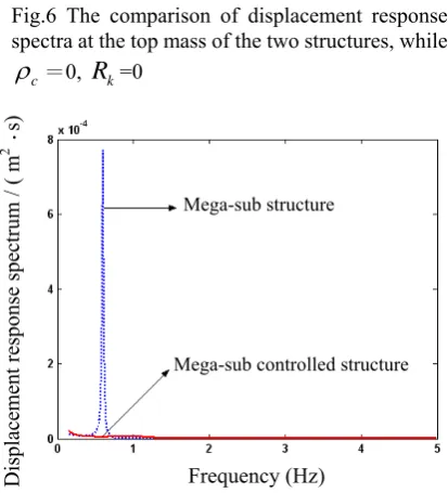
Fig.6 presents the comparison of displacement response spectra at the top mass of conventional MSS and the top mega-mass of MSCS when the damping device is not installed, i.e.
ρ
c=0,R
k=0. It shows that the displacement responses spectra of mega-sub controlled structure are decreased obviously compared with meg-sub structure. The MSCS exhibits a nice characteristic of self-control.Fig. 7 presents the same comparison, while
ρ
c =1.3, kR
=0. In this case the response spectrum of the mega-sub-controlled structure is much less than the status asc
ρ
= 0, the MSCS have an extraordinary control effectiveness compared with conventional mega-sub Fig.4 Time history curve of displacement at the topmass of the MSS and the top mega-mass of the MSCS, while
ρ
c=0,R
k=0Displacement(m)
Time(s )
Fig.5 Time history curve of acceleration at the top mass of the MSS and the top mega-mass of the MSCS, while
ρ
c=0,R
k=0Acceleration(m
⋅
s -2 ) [image:4.595.321.534.259.716.2]Time(s)
Fig.6 The comparison of displacement response spectra at the top mass of the two structures, while
c
ρ
=0,R
k=0Frequency (Hz)
Mega-sub controlled structure Mega-sub structure
Displacement response spectrum / (
m
2
⋅
s)
Mega-sub controlled structure Mega-sub structure
Displacement response spectrum / ( m
2
⋅
s)
Fig.7 The comparison of displacement response spectra at the top mass of the two structures, while
c
ρ
=1.3,R
k=0 [image:4.595.327.534.430.658.2] [image:4.595.56.267.437.602.2]structure. It could be confirmed that, the structure response is reduced and the control effectiveness is improved as the additional damping is acceded to system properly.
To investigate the influence of additional columns, Fig. 8~11 further present the square root values of mean square displacement and acceleration responses at the top mega-mass of mega-frame and at the top sub mass of substructure as
ρ
c =0~3,R
k =0~1.3. The four Figures clearly approve that the responses of MSCS are decreased when the damping value is increased. Fig.8 and 9 also shows that, when damping value is small, such asρ
c<0.6, the displacement and acceleration are unchangeable basically as the additional column stiffness ratioR
k is increased; when damping value is chosen as biggish, the displacement and acceleration response is decreased slightly first and then not changing with the increasingR
k.Fig.10 and 11 show that when damper is not installed in the system, i.e.
ρ
c=0, the responses are influenced greatly byR
k: whileρ
k<0.3, the displacements and acceleration of substructure decline remarkably asρ
k is increased, and then are unaltered whileρ
k>0.3. It is analyzed that because when the damper is not installed, the existence of additional columns has an effect of restriction on the relative movement between the mega-frame and substructure, the movement of substructure is limited especially, thus the displacement and acceleration of substructure are all decreased. After damper device is installed, the responses are uninfluenced by additional columns and the response values are much smaller.It is obvious that the interaction between the damper devices and additional columns make the responses of this system decreased enormously. It is revealed that the additional columns have a peculiar action on improving the degree of comfort of the structure. From the view of engineering design, a bigger
ρ
k can solve the difficulty of large span. This implies that it may be possible to acquire a much higherρ
k, a suitable value forρ
k would be in 30 – 60 % range.Fig.8 Square root values of the mean square displacement responses at the top mega-mass of mega-frame while
ρ
c=0~3, Rk=0~1.30 1
2 3
0 0.5 1 1.5
2 4 6 8 10
x 10-3
c
ρ
Displacement(m)
k
R
Fig.11 Square root values of the mean square acceleration responses at the top sub-mass of second substructure while
ρ
c=0~3, Rk =0~1.30 1
2 3
0 0.5 1 1.5
0 0.05 0.1 0.15 0.2 0.25
k
R
c
ρ
Acceleration(m
⋅
s -2)Fig.10 Square root values of the mean square displacement responses at the top sub-mass of substructure while
ρ
c=0~3,R
k=0~1.30 1
2 3
0 0.5 1 1.5
0 0.002 0.004 0.006 0.008 0.01
c
ρ
k
R
Displacement(m)
Fig.9 Square root values of the mean square acceleration responses at the top mega-mass of mega-frame while
ρ
c=0~3,R
k=0~1.30 1
2 3
0 0.5 1 1.5
0 0.05 0.1 0.15 0.2
k
R
c
ρ
Acceleration(m
IV. CONCLUSIONS
A new improved structural configuration of the practical mega-sub controlled structure is proposed for super tall buildings. The analytical and numerical studies undertaken in this paper illustrate that the mega-sub controlled structure acts as a self-controlled structure that is capable of reducing structure response induced in the system subjected to rand wind loads. From the results it could be concluded that this structural configuration can effectively resolve the existing problem mentioned above, and has a very strong ability in controlling wind responses.
REFERENCES
[1] G W Housner, et al, “Structural control: Past, present, and future,” J. of Engng. Mech. Vol. 9, 1997, pp. 899-907.
[2] MQ. Feng and A. Mita, “Vibration control of tall buildings using mega-sub configuration,” ASCE. Journal of Engineering Mechanics,
121(10), 1995, pp.1082-1087.
[3] W Chai and MQ. Feng, “Vibration control of super tall buildings subjected to wind loads,” Int. J. Non-linear Mechanics, 32(4), 1997,
pp.657-668.
[4] XA Zhang, JL Zhang and JS Jiang, “The influence of mega-substructural stiffness on the dynamic property of the shock-absorption-structure system of mega-frame,” Journal of northwestern polythchnical university, 22(1), 2004, pp.59-63.
[5] XA Zhang and JS Jiang, “The random responses of internal force for tall TV towers under wind loads,” Journal of Northwestern Polytechnical University, 18(5), 2000, pp.179-182
[6] T.K.Caughey and M.E.J.O’Kelly, “Classical normal modes in damped linear dynamic systems,” Journal of Applied Mechanics – ASME, vol.32, 1965, pp.583-588.
[7] T Fang, Engineering random vibration, Beijing: First edition, The Press of National Defense Industry, 1995, pp.64-67.
[8] YH Zhang and QZ Liang, “The earthquake resistant philosophy and
initial design of megaframe with suspension systems,” Engineering Mechanics, 17(2), 2000, pp.10-17.
[9] XJ Qin, XA Zhang and C Sheldon, “Study on semi-active control of mega-sub controlled structure by MR damper subjected to random wind loads,” Earthquake Engineering and Engineering Vibration, 7(3), 2008,