Abstract—In this paper, data error in sensor system using electromagnetic wave such as GPS and mobile communication is handled. To be specific, a localization that gives acceptable performance in indoor application is considered. The system uses CSS and SDS-TWR to improve system performance. However in multi-path environment, the transmitted signal is corrupted by environment adding reflected signals to the one of line of sight. Three kinds of factors, reflection coefficient, phase difference, and time difference, are related to added noise signals and determined from structural and material characteristics of environment. We propose a method how to estimate error in measured data for given simplified environment and we verify by experiment that the proposed technique estimate the error term in acceptable range.
Index Terms—Multipath, CSS, Localization, Indoor GPS, LBS
I. INTRODUCTION
Currently, localization systems are regarded as core technologies of ubiquitous society and are researched by many groups in universities as well as companies [1], [2]. Especially, various Location Based Service (LBS) navigation system and mobile communication using global Positioning System (GPS) systems are becoming important technology in our life. But in shading area of electromagnetic waves in indoor place, forest and tunnel, we need new localization system, because current localization system using GPS satellite or mobile communication is inaccurate in those areas [3]. So development of new localization systems to use in those areas is needed.
Current wireless localization systems need infrastructures composed of wireless stations, communicating devices, and so on. In these systems, one of the methods to measure the distance between devices considers propagation time of wave [4]. In such cases, time synchronization between devices to measure accurate time is most important issue. However, time synchronization up to usually nanosecond resolution is not easy at all [5]. Moreover, wireless system has interference
Manuscript received July 17, 2009. This work was supported in part by the Korea Research Foundation(KRF) grant funded by the Korea govemment(MEST)(No. 2009-0065440)
Hangoo Kang is with BK21 Mechatronics Group at Chungnam National University, Daejeon, Republic of Korea, 220 Gung-dong, Deajeon 205-764, South Korea(phone: +82-42-821-7783; fax: +82-42-823-4941; e-mail: [email protected]).
Geon woong Seo is with Department of Mechatronics Engineering of Chungnam National University, 220 Gung-dong, Deajeon 205-764, South Korea(e-mail: [email protected]).
*Jihong Lee is with BK21 Mechatronics Group at Chungnam National
University, Daejeon, Republic of Korea, 220 Gung-dong, Deajeon 205-764, South Korea(e-mail: [email protected]).
problem. In multi-path environment, waves are inevitably corrupted [6].
The main contribution of this paper is to propose a new way to measure the distance between devices accurately with the corrupted waves. To solve the interference problem and time synchronization, we use Chirp Spread Spectrum (CSS) and Symmetric Double Sided Two-Way Ranging (SDS-TWR)[7] which, in indoor environments, can be expected to give us good performance. And the places where are impossible to catch up GPS signal, are our main target place to use the proposed system.
Even when CSS is used, the signals are corrupted with noises determined three kind of factors comprised of reflection coefficient, phase difference, and time difference. The time difference can be calculated by arrival time of signals. But finding reflection coefficient and phase difference is hard word. So we are going to find true value of three factors in given environment through experiment.
This work is constructed as follow. In chapter II, CSS and SDS-TWR are introduced. In chapter III, problem statement of indoor wave propagation and wave signal equation including multi-path signals are introduced. Also structural and material characteristic which affect generated signal and measured data analyzed in the section. Real measurement of distance and error estimation is handled in chapter IV. Finally in chapter V, conclusion and future works are described.
II. BASICS OF RANGING SYSTEM A. CSS(Chirp Spread Spectrum)
CSS is defined as carrier waves frequency of which is increasing/decreasing regularly (Up Chirp/Down Chirp). CSS equation is defined by (1) and (2) for up chirp and down chirp, respectively.
)]
(
)
(
[
]
)
2
(
exp[
)
(
0 cc BW s
c
t
t
u
t
t
T
T
j
t
S
=
ω
+
ω
+
θ
×
−
−
(1))]
(
)
(
[
]
)
2
(
exp[
)
(
0 cc BW s
c
t
t
u
t
t
T
T
j
t
S
=
ω
−
ω
+
θ
×
−
−
(2)where is initial frequency, is bandwidth of signal, and is duration time of signal. Also note that u is step function.
CSS is used in many parts of wireless environment because chirp signal can be generated and amplified easily inside devices. Especially, it has good performance in interference environment, i.e., being different from sinusoidal signal which disappears when two signals with
Error Compensation for CSS-based
Localization System
180o phase difference are overlapped CSS is resistance to multi-path fading. And also Chirp Signal has good correlation properties. Fig. 1 shows chirp signals with regularly increasing, decreasing frequency (Up Chirp/Down Chirp).
(a) Up chirp pulse
(b) Up chirp frequency
(c) Down chirp pulse
[image:2.595.51.261.472.632.2](d) Down chirp frequency Fig. 1. Pulse and frequency variation of chirp signal
[image:2.595.320.534.562.736.2]B. Two-way TOA based ranging
Fig. 2. Exchange of message in SDS-TWR
Between two devices in two-way ranging system, distance is measured using Time of Arrival (TOA). To measure the distance, at first device A transmits signal and then device B receives that signal. And after small processing time ( ), device B transmits a second signal and device A receives that signal. By doing so, even time synchronization is not constituted, device A can calculate the travelling time between devices as far as the processing time is known. In more detail, whole delayed time includes wave propagation time and processing time ( ) in device B. So if device A knew the processing time in device B, device A can
calculate round trip time () of signal. This system does not need time synchronous. To make the data more accurate, the same process in made once again from device B side. And finally we get the traveling time between the devices as follows. With the traveling time of wave the distance is calculated by the speed of light as equation (3).
p replyA rounB replyB rounA
t c t
t t t c
d = − + − = ⋅
4 δ
(3) But in multi-path environments, there may exist more paths for the signals and so the traveling time may not be correct. Because device cannot discriminate Line-of-Sight(LOS) signal from multi-path signal.
III. PROBLEM STATEMENT A. Factors of error in localization system
The cause of error can be classified internal factors and external factors in localization system. Error in localizing robot is caused from internal factors and external factors.
Internal factors may include crystal offset, processing delay of electric circuit and accuracy of estimation counter in transmission and receive. For these factors are removed, the limit of current hardware technique can be extended.
External factors include Non-Line-of-Sight(NLOS) error and multipath error. NLOS error happens when there are no direct path between the transmitter and receiver. Only reflected or diffracted signals arrives at the receiver, when the direct path is blocked by objects. This makes the signal to arrive later, leaving a positive error to the TOA measurement. The NLOS path can be much longer than the LOS path resulting in large errors. So it is important to find an away to mitigate NLOS errors. Multipath error is occurred by reception of multiple signals at a sensor, which are received with different amplitudes, delays and phases. Multiple signals arise mainly from reflection or refraction of the original signal transmitted. These signals can combine constructively or destructively resulting in fading.
This fading makes it difficult to accurately determine the range in wireless systems. Devices designed to estimate range from time delays uses correlator to compute the arrival time of the signal. When multiple signals arrive, the correlator will be confused and will not know the exact time of the arrival even when a LOS path exists.
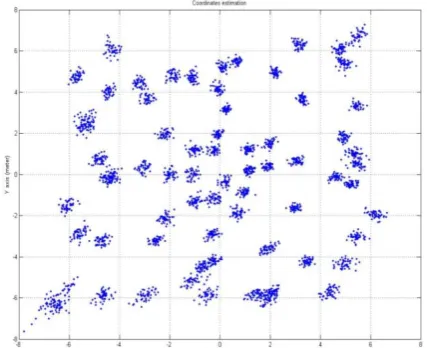
Fig. 3 shows a preliminary result. We made an experiment in LOS and multipath environment where is the rooftop. Each anchor was fixed at corners of a 10 meter square. 5 anchors are installed ath (-5m, 5m), (5m, 5m), (5m, -5m), and (-5m, -5m). And tag positions were set at every 1m along vertical and horizontal. 100 samples were acquired at each different point depicted in fig. 3. The localization system has maximum 4m errors. Since each anchor is in different situations(reflecting wall, ground, and differences in circuit), the amount of errors, we guess, are different for every case.
B. Mathematical model of multipath signal
In compensating error for CSS-based localization system, there are many problems to be solved. Among them, we handle problems of multipath in this paper. The multipath signal can be described as the following equation.
) ( ) 180 / exp( )
( ) (
1
i i
n
i i
t j
t t
h =δ +
∑
α θπ δ −τ= (4)
In equation (4), the first term is a direct-path signal, the second term is multipath signals, α is reflection coefficient, θ is phase difference and n is number of multipath. In conclusion, α and θ of above equation are to be specified.
IV. ERROR COMPENSATION AND CASE STUDIES In this chapter, real measurements of CSS ranging is acquired, when only LOS exist and multipath exist with LOS. Also ranging performance of CSS-based localization system under the existence of multipath is analyzed through computer simulation and compared with the experiment results. The simulation is performed using Matlab and the experiment is performed using CSS transmitters and receivers devices from Nanotron Tech[8].
[image:3.595.342.525.349.742.2]A. Experimental Equipment
Fig 3. The localization system(Nexbee)
The Nexbee in fig. 3, used in this research and is manufactured by Corebell[9], The Nexbee is a module of localization system and is known to adopt the zigbee communication based on CSS. And the Nexbee has a nanoLOC chip developed by Nanotron. The nanoLOC calculates distance through wireless communication and works around 500m range. Basic system consists of one tag and four anchors. Note that in the system time synchronous is not required because the nexbee uses round trip of a signal. Delay Lock Loop(DLL)[10], [11] is applied to find exact time of arrival. The DLL will be introduced at error of estimation section.
B. Case of only LOS
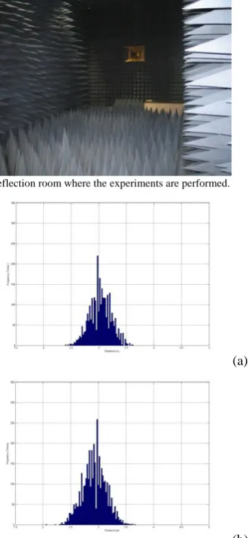
First, for verification of performed actual experiment environment, sample data are acquired in no reflection room where there is no reflection and no external interference. Fig. 4 shows the no reflection room. 3000 samples were collected for the distance of 3m at the no reflection room as well as on the rooftop of our building. Fig. 5 show that is histograms of measured results. Measured mean value is very similar with real distance as Table I. thus we performed the rooftop of our building.
Fig 4. No reflection room where the experiments are performed.
(a)
[image:3.595.55.278.577.774.2]TABLE I. Results of 1-dimension measurement in no reflection room & rooftop
Environment Mean(m) Variance(m)
No reflection room 3.02 0.193
Rooftop 2.93 0.212
C. Case of with multipath
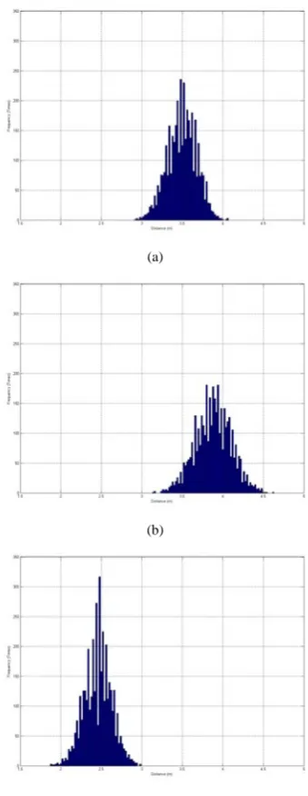
[image:4.595.54.283.300.453.2]Experiment is made in multipath environment as fig. 6. The distance(d) between the transmitter and the receiver is fixed 3m. The reflector is an iron plate. The position(h) of reflector is set up to 1m, 2m and 3m, respectively. 3000 samples were acquired at each position of reflector. When the position of reflector is 1m and 2m, the measurement results were longer than 3m in fig. 7. However, when the position of reflector is 3m, the measurement result was shorter than 3m in fig. 6. Next section, simulations including environment will be performed, and through the simulations error of the will estimated.
Fig 6. The conceptual experimental environment
TABLE II. Results of distance measurement in multipath environment
h(m) Mean(m) Variance(m)
1 3.50 0.178
2 3.88 0.223
3 2.46 0.171
D. Estimating error for compensation
In this section, we assumed a two-ray multipath to analyze ranging errors caused by multipath signals. To detect the exact time of arrival effectively a Delay Lock Loop(DLL) is used. To measure the propagation time from the transmitter to the receiver, the receiver needs to detect the signal arrivals properly in exact time information. The receivers continuously operate a correlator which correlates the received signal generated signal. When the correlation power is the maximum then the receiver indicates that a proper signal is received. The peak of the autocorrelation is achieved when the self-generated signal is matched exactly the received signal. And the peak time is recorded. Fig. 8 shows the peak of the autocorrelation function of chirp signal of localization system. But tracking the peak point of autocorrelation function precisely is very hard in real-time applications because the slope of the autocorrelation function is very steep. Therefore the receivers apply a DLL to track the
(a)
(b)
(c)
Fig 7. Histograms of 1-dimension measurement in multipath, when h is (a)1m, (b)2m and (c)3m
[image:4.595.345.509.622.745.2]signal. The DLL correlates the received signal with early reproduction of the signal and late reproduction of the signal. When the received signal is locked, the early correlator and the late correlator sample the peak of the correlation function on the rising edge and the falling edge. The early samples and the late samples are denoted as equation. (5)(6)
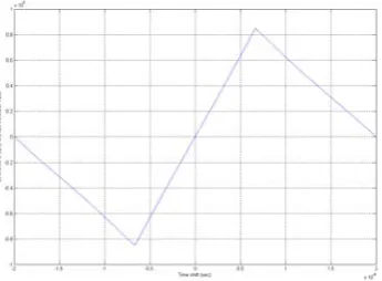
Fig 9. Difference in early and late correlator values.
E E E S N
Sˆ = + (5) E
L L S N
Sˆ = + (6)
where SE is the signal of the early sample and NEis noise component of the early sample. Then the difference in the early and late correlator value is applied to estimate the peak. When the difference is zero, it is the peak time. This function is given by equation. (7).
L E L E L
E S S S N N
S
D = ˆ − ˆ = ˆ − ˆ + − (7)
When there is no noise(NE, NL), D will be zero when SE and
NE have the same value because of the symmetry of the autocorrelation peak. Difference in early and late are plotted in fig. 9.
To analyze the multipath problems, the two-ray model is applied for simplicity which is depicted in fig. 10. Fig 10 is results of DLL for 3cases. When h is 1m(a), 2m(b) and 3m(c), respectively zero crossing point is 0.109
×
10-8 sec, 0.109×
10-8 sec and -0.227×
10-8 sec respectively.Fig 10. Results of DLL for 3 cases. (a)h=1, (b)h=2, (c)h=3
A transmitted signal reaches the receiver through LOS path and a reflected path signal which arrives at the receiver with time delay, reduced power and phase difference. The transfer function representing the two-ray path characteristics may be expressed in impulse response as follows[12].
) ( ) 180 / exp( )
( )
(t = δ t +α jθπ δ t−τ
h (8)
where α and θ present the reflection coefficient and phase difference of the multipath. t is the time delay of the second path relative to the LOS path. The autocorrelation function is symmetric when there are no multipath signals, while the autocorrelation function with the multipath is not. Thus the zero crossing points are changed. By calculating time difference between early and late samples in the zero crossing point and multiplying it by the correlator sampling rate and speed of light, we can estimate the range error.
With the experimental results of 3 cases, in equation (8) we tried to select the reflection coefficient and phase difference as 0.6 and 138o respectively, and get Table III. Note that estimation errors are obtained through DLL method with the trial values as fig. 10. Clearness of reflector surface and diffraction of electromagnetic waves at the edges of reflector are believed to be the source of estimation errors.
TABLE III. Experiment error & Estimation error when measurement distance is 3m.
h Error in experiments Estimated error value with α=0.6 and θ=138o
1m 0.50m 0.20m
2m 0.88m 1.00m
3m -0.52m -0.54m
[image:5.595.306.549.485.543.2] [image:5.595.73.277.495.639.2]
To show the trial values are best estimation for reflection coefficient and phase difference, we give other set of simulation with 0.7 and 131o as well as 0.5 and 145o for reflection coefficient and phase difference. So we obtained result as Table IV. Note that the sum of squared error of Table III is 0.1048. Note that the sum of squared errors is 0.1195 and 0.1614 in Table IV cases.
TABLE IV. Trial parameters
h α=0.7 and θ=131o α=0.5 and θ=145o
1m 0.27m 0.12m
2m 1.09m 0.89m
3m -0.67m -0.39m
V. CONCLUSION
In this paper, we made experiment for the performance of Nexbee which is one of CSS-based localization system and confirmed motivation for error compensation. Among the sources of error, we focused on the multipath problem, and then we set up mathematical model for the errors which includes reflection coefficients and phase differences in multipath environment. By a set of experiments and analysis of the results in simplified environment, the parameters of the model are extracted. The parameters give admissible results with real measurements.
REFERENCES
[1] Paramvir Bahl, Venkata N padmanabhan, “RADAR: An In-Building RF-based User Location and Tracking System”, Proc. IEEE Infocom 2000, IEEE Press, Piscataway, N.J., 2000.
[2] Lionel M. Ni, Yunhao Liu, Yiu Cho Lau, Abhishek P. Patil, “LANDMARC: Indoor Location Sensing Using Active RFID”, Proc. 1st IEEE Int’l Conf. Pervasive Computing and Communication, IEEE
CS Press, 2003.
[3] Didier Johannes Richard VAN NEE, Multipath and Multi-Transmitter Interference in Spread-Spectrum Communication and Navigation Systems, Delft University Press, 1995.
[4] N. Khajehenouri and A.H. Sayed, “A non-line-of-sight equalization scheme for wireless cellular location”, IEEE Trans. Veh. Technol., Vol.52, no. 1.
[5] G. P. Yost and S. Panchapakesan, “Improvement in Estimation of Time of Arrrval(TOA) from Timing Advance(TA)”, IEEE International Conference on Universal Personal Communications, Vol. 2, Oct, 1988. [6] Kim, Eui Seok “Ranging Performance of Chirp Spread Spectrum in in
door multipath environment,” M.S. thesis, Department of Electrical E ngineering and Computer Science College of Engineering. Seoul Nati onal University, Korea, 2008
[7] Zafer Sahinoglu, Sinan Gezici, “Ranging in the IEEE 802.15.4a Standard,” Mitsubishi Electric Research Laboratories, 2006
[8] Nanotron, [Online]. Available http://www.nanotron.com
[9] Corebell, [Online]. Available http://www.corebell.co.kr
[10] E. D. Kaplan, Understanding GPS: Principles and Applications, Artech House Inc., 1996
[11] Il Heung Chio “A Multipath Mitigation Method Using the slope Change of autocorrelation Function ”Department of Electronics Engineering, Chungnam National University, Korea, 2003