© 2019, IRJET | Impact Factor value: 7.211 | ISO 9001:2008 Certified Journal
| Page 2442
Grid Connected Third Harmonic Injection PWM in a Multilevel Inverter
Control with Proportional Resonant Controller
G Raviteja
1, G Satya pratap
21
M Tech Scholar, Department of EEE, KIET College, Kakinada, Andhra Pradesh, India
2
Assistant Professor, Department of EEE, KIET College, Kakinada, Andhra Pradesh, India
---***---
Abstract: This project presents a grid connected system. Three phase DC-AC inverters used to convert the regulated DC power To AC power suitable for grid connection. In order to reduce the harmonic component or total harmonic distortion (THD) techniques third harmonic injected pulse width modulation (PWM) techniques are used. The third harmonic injected PWM (THIPWM) is widely used for lower THD. In this paper, P+ multi resonant controller has been used to compensate the voltage harmonics. The accurate generation of THIPWM minimize the THD and make the inverter suitable for grid connection, by, P+ multi resonant controller synchronizing the inverter voltage with the grid voltage. The application of THIPWM to inverter increases efficiency of the inverter. Simulation results validate the developed model and the proposed system.
Key Words: Nonlinear Load; Harmonic Compensation;
Proportional-Resonant (PR) Controller, Resonant Controller,
Grid Voltage Harmonics, PWM, THIPWM, THIPWM, THD .
1. INTRODUCTION
In last few years focus on renewable energy sources like wind, solar and hydro and their use in power generation has led to develop new techniques to control and synchronize them with the grid. Many inverter topologies have been discovered to reduce current ripples in grid connected systems with these renewable power sources as their input. These grid connected renewable sources improves stability of the grid by supplying active power during peak demand. But these have some disadvantages like introduction of harmonics in the grid current; power generation completely depends upon environmental condition etc. In grid, current harmonics should be limited up to 5% as per IEEE-519 standard. Pulse width modulation (PWM) switching technique for inverter is widely used for dc signal to ac signal conversion. For fixed switching frequency, low ripple current and well defined harmonic spectrum characteristics, PWM techniques are popularly used for different types of inverter [1], [2]. The PWM signals are generated by comparing a reference signal with a carrier signal. The reference signal is in the form of sinusoidal or square wave and the carrier signal may be triangular or saw tooth wave where the carrier signal frequency is greater than the reference signal frequency [3]. By comparing the reference signal and carrier signal, the triggering pulses are generated which turn on and turn off the inverter leg switches.
According to the different types of major reference signals, PWM techniques can be divided into different categories
Such as sine PWM, third harmonic injected PWM, sixty degree PWM, trapezoidal PWM etc. These techniques reduce the number of switching which reduces the switching loss [4]. Based on the total harmonic distortion (THD) analysis, third harmonic injected PWM (THPWM) is better among them [5]. THD is the measurement of harmonic distortion present in the output signal of the inverter. THD should be kept as low as possible because higher THD has unfavorable effect on power supply
Control of feeding active and reactive power to the grid is a big deal. Simple PI controllers are used commonly but they have certain drawbacks like steady sate error in stationary reference frame and necessity to decouple phase dependency in three phase system etc. They are easy to implement [3]. Newly developed PR controller (proportional resonant controller) and harmonic compensator [4] is absolutely free from above mentions problems and can be implemented in a cheap fixed-point DSP [along with filter in the common coupling point to reduce current harmonics. LC filter has great harmonics suppression capability [4] but it sometime makes the system response oscillatory. Instead of that in this paper L filter has been used. Here, thin phase disposition (IPD)’ PWM technique has been adopted for 7 level diode clamped multilevel inverter.
2. THIRD HARMONIC INJECTED PWM
© 2019, IRJET | Impact Factor value: 7.211 | ISO 9001:2008 Certified Journal
| Page 2443
3. PROPORTIONAL RESONANT
Resonant Controllers are based on the Internal Model Principle (IMP) [16], which states that a very good tracking for a reference or a rejection for disturbances signals is ensured if the closed-loop system is stable. Its main characteristic is to introduce infinite gain at certain resonant frequency that should equal to the periodic reference signal frequency. The transfer function of this controller with sinusoidal internal model is According to IMP, if the closed-loop stability is guaranteed, then the resonant controller defined in (1) ensures zero steady state error for sinusoidal tracking (disturbance rejection) at frequency wr. This PR controller described by (4) is considered an ideal controller and as shown from Bode diagram in Fig.3 that it has a theoretically infinite gain at the frequency wr which enables it to ensure zero steady-state error at this frequency only and introduces no gain or phase shift at other frequencies. This infinite gain of the ideal controller may lead to difficulty in the implementation with either analogue or digital system .Furthermore in this ideal controller it is not possible to select proper gain and width for the controller which reduces the controller design flexibility and may lead to stability problems. So instead of using this ideal controller described above, it is better to use the non-ideal form of the controller which has a finite gain that is still relatively high for good tracking performance to ensure zero steady state error. The Bode plot of non-ideal PR control The PR current controller GPR(s) is represented by:
.
3.1 HARMONIC COMPENSATORS DESIGN
Harmonic compensators were designed for the 3rd, 5th and 7th harmonics. The PR harmonic Compensators were designed using SISO Tool in Matlab with the resonant frequency set to the particular frequency to be compensated, i.e. 150Hz for the 3rd harmonic, 250Hz for the 5th harmonic and 350Hz for the 7th harmonic. Similarly to the fundamental PR current control design, the Root Locus, Open Loop and Closed Loop Bode diagrams plotted by SISO Tool were used to achieve the optimal design for each harmonic compensator. Each harmonic compensator was designed on its own and then combined together with the fundamental PR controller at the end in SISO Tool. Ultimately fine tuning of the compensators was performed to obtain the optimum operation of the compensators by varying ωc and KI of the
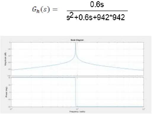
corresponding compensator. Care was taken that the system remains stable, by using the gain margin and phase margin stability criteria. The 3rd harmonic compensator at a resonant frequency 3ω0 of 942.48rad/s (150Hz) was
designed with a ωcof 0.3 rad/s and a KIof 1. Open Loop and
[image:2.595.308.565.138.332.2]Closed Loop Bode diagrams plotted by SISO Tool matlab shown in fig.4.2.
Figure 1 Non-ideal proportional resonant 3rd harmonic compensator controller Bode diagram
The 5th harmonic compensator at a resonant frequency 5ω0
of 1570rad/s (250Hz) was designed with a ωcof 4.2 rad/s
and a KIof 1. . Open Loop and Closed Loop Bode diagrams
plotted by SISO Tool matlab shown in fig.4.3.
Figure 2 Non-ideal proportional resonant 5rd harmonic compensator controller Bode diagram
The 7th harmonic compensator at a resonant frequency 7ω0
of 2199rad/s (350Hz) was designed with a ωcof 2 rad/s and
a KIof 1. Open Loop and Closed Loop Bode diagrams plotted
[image:2.595.309.573.437.617.2]© 2019, IRJET | Impact Factor value: 7.211 | ISO 9001:2008 Certified Journal
| Page 2444
Figure 3 Non-ideal proportional resonant 7rd harmonic compensator controller Bode diagram
[image:3.595.44.280.350.522.2]The transfer function of the complete controller GC(s) is shown in
Figure 4 Non-ideal proportional resonant GC(s) harmonic compensator controller Bode diagram
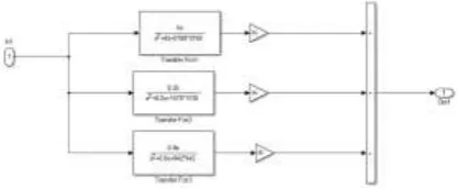
The block diagram of the complete system used to design the selective harmonic compensators is shown in Fig. 3.
Figure 5 the selective harmonic compensators
4. DIODE CLAMPED MULTI LEVEL INVERTER
The first invention in multilevel converters was the so-called neutral point clamped inverter. It was initially
proposed as a three level inverter. It has been shown that the principle of diode clamping can Extended to any level. A diode clamped leg circuit is shown in Figure.
The main advantages and disadvantages of this topology are:
Advantages:
• High efficiency for the fundamental switching frequency.
• The capacitors can be pre-charged together at the desired voltage level.
• The capacitance requirement of the inverter is minimized due to all phases sharing a Common DC link.
Disadvantages:
• Packaging for inverters with a high number of levels could be a problem due to the Quadratically relation between the number of diodes and the numbers of levels.
• Intermediate DC levels tend to be uneven without the appropriate control making the real
Power transmission a problem.
• Uneven rating in the diodes needed for the converter.
Some of the applications using Multilevel Diode Clamped converters are:
• An interface between High voltage DC transmission line and AC transmission line.
• High power medium voltage variable speed drives.
• Static VAR compensate
4.1 Neutral Point-Clamped Inverter: A seven-level diode- Clamped inverter
[image:3.595.61.270.605.691.2]© 2019, IRJET | Impact Factor value: 7.211 | ISO 9001:2008 Certified Journal
| Page 2445
[image:4.595.64.266.262.447.2]which is Vdc /2. If the output is removed out between a and 0, then the circuit becomes a dc/dc converter, which has three output voltage levels: Vdc ,Vdc/2, and 0.Considering that m is the number of steps of the phase voltage with respect to the negative terminal of the inverter, then the number of steps in the voltage between two phases of the load k is k = 2m+1 (1) and the number of steps p in the phase voltage of a three-phase load in wye connection is p = 2k – 1. By increasing the number of levels in the inverter, the output voltages have more steps generating a staircase waveform, which has a reduced harmonic distortion. However, a high number of levels increases the control complexity and introduces voltage imbalance problems.
Figure 10 A seven-level diode-clamped converter
Figure 11 A Three phase seven-level diode-clamped inverter
Fig. 1(a) shows a seven-level diode-clamped converter in which the dc bus consists of four capacitors, C1, C2, C3, C4,C5 and C6. For dc-bus voltage Vdc, the voltage across each capacitor is Vdc/6, and each device voltage stress will be limited to one capacitor voltage level Vdc/6 through
[image:4.595.310.560.331.449.2]clamping To explain how the staircase voltage is synthesized, the neutral point n is considered as the output phase voltage reference point
Table I. Switching States of the Seven Level Inverter
[image:4.595.49.276.491.667.2]There are seven types of voltage level in seven level inverter. i.e. 0v, Vdc/3, -Vdc/3, 2Vdc/3, -2Vdc/3,-Vdc and Vdc. Now for a particular voltage level there will be certain switch which will remain on and specific capacitors will discharge.
Figure 12 voltage level in seven level inverter
5 PR BASED CONTROL SCHEME
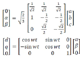
Here essential coordinate conversions are abc to αβ0 (Clarke transformation) and αβ0 to dq0(park’s transformation)
[image:4.595.338.506.551.674.2]© 2019, IRJET | Impact Factor value: 7.211 | ISO 9001:2008 Certified Journal
| Page 2446
[image:5.595.45.276.286.506.2]5.1 PR BASED CONTROL SCHEME WITH SPWM
Figure 13 PR based output voltage control scheme.
Grid voltage va,vb,vc converted into , using Clarke
transformation. For generation ideal voltage v ref abc (without
harmonics) park’s transformation is used abc to dq0 to get magnitude of voltage and noise reduced by low pass filter .pll is responsible wt in sin function .reference voltage v ref abc is converted in v new .ref αβ using Clarke transformation. Now
Grid voltage , is subtracting from reference voltage v
new .ref αβ output is given to pr controller . Inverter current ilabc
is converted in l αβ subtracting from pr controller output to
[image:5.595.337.532.346.528.2]get pure sinusoidal wave for PWM modulator
Figure 14 Proposed PR based in MATLAB.
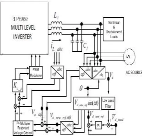
5.2 PR BASED CONTROL SCHEME WITH THIPWM
Figure 15 PR WITH THIPWM based output voltage control scheme
Grid voltage va,vb,vc converted into , using Clarke
transformation. For generation ideal voltage v ref abc (without
harmonics) park’s transformation is used abc to dq0 to get magnitude of voltage and noise reduced by low pass filter .pll is responsible wt in sin function. reference voltage v ref abc is
converted in v new .ref αβ using Clarke transformation. Now
Grid voltage , is subtracting from reference voltage v
new .ref αβ output is given to pr controller . Inverter current
ilabc is converted in l αβ subtracting from pr controller
© 2019, IRJET | Impact Factor value: 7.211 | ISO 9001:2008 Certified Journal
| Page 2447
carrier signal, triggering pulses are generated give to multilevel inverter.
6. SIMULATION RESULT
6.1 PR BASED INVERTER WITH SPWM
[image:6.595.309.564.78.214.2]Figure 16 based inverter with spwm in matlab
[image:6.595.56.269.179.343.2]Figure 17 inverter with spwm voltage output in matlab
[image:6.595.322.545.246.401.2]Figure 18 FFT analysis inverter with spwm voltage output in matlab
[image:6.595.329.542.484.587.2]Figure 19 inverter with spwm current output in matlab
Figure 20 FFT analysis inverter with spwm current output in matlab
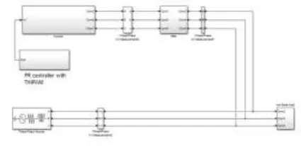
6.1PR BASED INVERTER WITH THIPWM IN MATLAB
Figure 21 pr based inverter with THIpwm in matlab
[image:6.595.46.276.536.696.2] [image:6.595.327.541.619.723.2]© 2019, IRJET | Impact Factor value: 7.211 | ISO 9001:2008 Certified Journal
| Page 2448
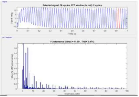
[image:7.595.62.264.296.390.2]Figure 23 FFT analysis inverter with THIpwm voltage output in matlab
Figure 24 inverter with THIpwm current output in matlab
Figure 25 FFT analysis inverter with spwm current output in matlab
7. COMPARTION BETWEEN WITH PR CONTROLLER BETWEEN SPWM AND PR THIPWM
PR CONTROLLER INVERTER WITH SPWM
PR
CONTROLLER INVERTER WITH THIPWM VOLTAGE
(THD%) 1.69 1.33
CURRENT
(THD%) 3.93 2.47
8. CONCLUSION
The design of a proportional resonant controller for three phase 7 level inverter with THIPMW for grid-connected applications.compartion between PR controller with SPWM between and PR controller with THIPWM is done. From the analysis and simulated data we can conclude that the PR controller with THIPWM technique provides better performance than PR controller with SPWM. The project is verified by the simulation results. It can be observed that the THD is very minimal and follows the IEEE standards. Hence the efficiency of inverter can be improved by using THIPWM technique.
9. REFERENCES
[1].Mohamed Elrais Tamas,Mohammed Saleh, Mahmoud Shaker, “Comparison of Different Third Harmonic Injected PWM Strategies for 5-Level Diode Clamped inverter”2017 3rd International Conference on Electrical Information and Communication Technology (EICT), 7-9 December 2017, Khulna, Bangladesh
[2].M.A.A. Youni,N. A. Rahim and S. Michele “Simulation of Grid Connected THIPWM-Three-Phase Inverter Using SIMULINK”2011 IEEE Symposium on Industrial Electronics and Applications (ISIEA2011), September 25-28, 2011, Langkawi, Malaysia
[3].Kyungbae Lim, Desmon Petrus Simatupang and Jaeho Choi‘’PR based Output Voltage Regulation for Harmonic Compensation under Islanded Mode of Microgrid with Magnitude Restoration’’2017 IEEE
[4].Mahmoud Elghonimy,M.Fawzi, A.E.Kalas, Gamal Abdel Azeem’’Proportional Resonant Controller with Resonant Harmonic Compensators for Three-Phase Static Frequency Converter Feeding Nonlinear Loads’’2017 Nineteenth International Middle East Power Systems Conference (MEPCON), Menoufia University, Egypt, 19-21 December 2017
[5] Devesh U. Sarkar,Harshit S. Dalvi.‘’Modeling and Designing of Solar Photovoltaic System with 3 Phase Grid Connected Inverter’’2017 2nd International Conference for Convergence in Technology (I2CT) ieee
[6].Daniel Zammit, Cyril Spiteri Staines, Maurice Apap, John Licari‘’Design of PR Current Control with Selective Harmonic Compensators using Matlab’’JESIT 150
[image:7.595.42.283.431.600.2]