DOI: 10.4236/ojst.2018.86021 June 29, 2018 217 Open Journal of Stomatology
Report of Case Series
Fares Kablan
Department of Oral and Maxillofacial Surgery, The Galilee Medical Center, Nahariya, Israel
Abstract
Purpose: Autogenous bone was still considered as the gold standard in bone augmentations prior to implants insertion at the atrophic ridges. However if large bone grafts are needed to augment multiple edentulous atrophic seg-ments, extraoral donor sites may be mandatory. The aim of this report is to introduce the Fares Wedge Technique, as a new bone augmentation method that can augment multiple edentulous ridges with intraoral cortical bone grafts. Methods: This report includes patients with moderate to severe ridge atrophy in different regions of the both jaws who were treated over 6-years period (2009-215) with wedge Technique (WT). Patients received panorex immediately after the surgery, and they were examined clinically and radio-graphically (periapical) every 2 weeks. At 4 months, computed tomography was performed to evaluate the bone gain. Reentry was performed after 4 to 5 months to evaluate the new bone volume and quality and to insert implants. At this stage specimens for histologic examination were also obtained. Re-sults: 39 augmentation sites in 22 patients (15 women, 7 men: mean age 47 years) were followed 12 to 52 months. The healing process was uneventful, with minimal morbidity. The success rate was 95%, and the bone gain average was 3 - 6 mm vertically and 3 - 9 mm horizontally. In two patients the graft was partially exposed and treated with shaving and rounding the exposed wedges, but the augmentations were saved. In one case the majority of the bone graft was lost. At 38 sites the patients had successfully received 114 im-plants. Conclusions: wedge technique can augment multiple segments of atrophic ridges with small amount of autogenic graft. The bone volume that achieved was satisfying, especially that the majority of the augmented areas How to cite this paper: Kablan, F. (2018)
The Use of Cortical Bone Wedges from the Mandibular Ramus “Wedge Technique”: For 3-Dimensional Bone Augmentation of the Atrophic Ridges. Technique Presenta-tion and Report of Case Series. Open Jour-nal of Stomatology, 8, 217-239.
https://doi.org/10.4236/ojst.2018.86021
Received: March 22, 2018 Accepted: June 26, 2018 Published: June 29, 2018
Copyright © 2018 by author and Scientific Research Publishing Inc. This work is licensed under the Creative Commons Attribution International License (CC BY 4.0).
DOI: 10.4236/ojst.2018.86021 218 Open Journal of Stomatology
1. Introduction
Alveolar bone loss is a result of teeth extractions, periodontal disease, trauma, pathologic conditions, failed implants, and failed bone expansion procedures may provide poor bone quality in height, width, angulation and impaired inter-maxillary relationships. Ridge augmentation may be considered in such cases to enhance placement of dental implants at a proper prosthetic position. Several augmentation methods and materials have been successfully used but much controversy still exists [1]-[10].
Autogenous bone grafts was still the gold standard due to their biological ac-tivities, their safety and their excellent incorporation in the recipient bed. Com-mon extra donor sites such as the iliac crest, rib, tibia, and calvarium are com-monly used and provide large quantities of bone. The main disadvantages of extraoral donor sites are: the need for hospitalization, general anesthesia, pro-longed healing time, co-morbidities, and visible scars [11]-[17].
Different intraoral donors sites are widely used as bone blocks and or as par-ticulate bone. The most typical intraoral donor sites are the chin and retromolar area [18][19][20][21][22]. They have different degrees of co-morbidities and complications [23][24][25][26][27].
Non autogenous bone grafts: allografts, xenografts, and synthetic bone are widely used either alone or in combinations [28]-[34]. They eliminate the poten-tial complications that associated with the donor site, their availability is unli-mited but typically lacks osteoinductive characteristics and osteoprogenitor cells to the recipient sites.
Autogenous bone graft healing goes through revascularization together with remodeling and substitution of the graft, which results in integration of the graft and the recipient bed [35]. There is a strong relationship between revasculariza-tion and osteogenesis inside and around the graft [36].
Revascularization of the bone graft begins when blood vessels sprouts grow and penetrate the bone block. They originate from two sources: 1) from the reci-pient bed, and 2) from the surrounding soft tissue. Hammack and Enneking in 1960 found that penetration of the blood vessels to the cortical graft occurred at the sixth day [37].
DOI: 10.4236/ojst.2018.86021 219 Open Journal of Stomatology
2. Patients and Method
During a 6-years period (2009-2015), the wedge technique was used to augment different sites of atrophic ridges (Table 1), and (Diagram 1). The majority of the patients were referred by their surgeons due to different types and degrees of al-veolar bone deficiencies, a lot of them were caused as a result of failed implants or failed previous bone augmentation attempts. Medically compromised patients such as patients with uncontrolled diabetes, history of bisphosphonates treat-ment, history of radiation therapy and heavy smokers were excluded from the study.
The patients that were treated with FWT, and were informed at admission about the diagnosis and the treatment alternatives. It was explained to all the potential patients how this treatment differed from familiar bone augmentation methods. Willing patients signed the consent form in which all the treatment sequence, possible complications, and post-surgical instructions were reported and explained. The patients underwent three-dimensional bone augmentation at least in one site in different arch regions to restore an atrophied alveolar ridge. The majority of the cases had: 1) at least two sites at one jaw or at the both jaws, and 2) the majority of the sites were at the posterior mandible. Indications for the use of wedge technique in the participants included, atrophic alveolar ridge with bone deficit that needs vertical, horizontal or combined vertical and hori-zontal bone augmentation.
The retromolar/ramus area was the donor site for the bone cortical wedges of this technique. Post-operative instructions include soft diet for six weeks, anti-biotics for ten days, meticulous oral hygiene and any use of removable appliance was not allowed.
DOI: 10.4236/ojst.2018.86021 220 Open Journal of Stomatology
3 3.5 28 F 13 - 23 10 - 12 1.5 - 2 RT
4 4.6 63 M 43 - 47 8 - 18 1.5 - 2.5 RT
4.7 34 - 37 6 - 11 2 - 4
5 5.8 29 F 32 - 42 9 - 12 1.5 - 3 RT
5.9 44 - 47 6 - 10 2 - 6
6 6.10 54 F 44 - 47 4.5 - 9 2 - 3.2 LT
6.11 35 - 37 6 - 10 2.8 - 3.5
7 7.12 54 F 44 - 47 6 - 10 3 - 4 LT
7.13 35 - 37 6 - 8 4 - 6
8 8.14 49 F 33 - 43 16 - 18 1.8 - 2.4 LT
8.15 36 - 37 8 - 10 1 - 2
9 9.16 63 M 35 - 37 7 - 9 2.5 - 5 LT
10 10.17 55 M 34 - 37 6 - 8 3 - 7 LT
11 11.18 47 F 34 - 37 5 - 7 2.4 - 4 RT
11.19 45 - 47 5 - 8 2.8 - 4
12.20 13 - 17 6 - 11 1.5 - 2.5
12 12.21 56 F 23 - 27 7 - 12 1.5 - 3 RT<
12.22 43 - 47 8 - 18 1 - 3
13 13.23 19 M 23 - 27 8 - 11 2.5 - 3.5 RT
14 14.24 39 F 43 - 47 5 - 7 6 - 8 LT
14.25 34 - 37 5 - 7 6 - 8
15 15.26 62 M 15 - 25 10 - 13 1 - 2 RT
16 16.27 67 M 34 - 36 5 - 7 2.4 - 4 LT
16.28 44 - 47 5 - 8 2.9 - 4
17 17-29 17-30 51 F 46 - 47 36 - 37 3.5 - 7 3 - 5 6 6 RT
18 18.31 30 F 12 - 15 8 - 11 2.5 - 3 RT
18.32 33 - 43 14 - 18 2 - 3
19.33 13 - 23 8 - 13 1.8 - 2.7
19 19.34 44 F 46 - 47 4 - 5 2 - 3 RT
19.35 34 - 37 6 - 7 3 - 4.5
20 20.36 20.37 54 F 44 - 47 35 - 37 3.5 - 4.8 4.6 - 5.2 4 - 5 3 - 6 RT
21 20.38 57 F 26 - 27 4 - 6 2 - 4 LT
[image:4.595.198.535.93.730.2]DOI: 10.4236/ojst.2018.86021 221 Open Journal of Stomatology
Diagram 1. Patients and augmented sites.
was made manually, that’s means the bone dimension after the surgery minus the initial bone dimension.
Reentry was performed after 4 to 5 months to evaluate the new bone volume, obtain biopsy specimens and insert implants. Patients were referred back to their dentists for prosthetic rehabilitation. Follow-up of the bone augmentations and implants that were inserted in these sites included periodic clinical evaluation and periapical radiographs. All the surgical procedures and postoperative evalu-ations were performed by the author.
2.1. Technique
Illustration case; 55 years old female was referred to pro-prosthetic unit at our department to augment her posterior mandible bilaterally in order to insert dental implants.
On examination; healthy patient with bilateral posterior mandibular edentul-ism (Kennedy class-1), lingually positioned and lingually angulated residual ridges (Figure 1(a)).
The computed tomography of her mandible demonstrated a moderate to se-vere atrophy of the both posterior mandibular ridges (Figure 1(b) and Figure 1(c)). Short implants are not option due to the severe lingual angulation of the ridges. Guided implants placement is not an optional treatment due to the cen-tral position of the inferior alveolar nerve. This case necessitated bone augmen-tation that was treated with the WT.
2.2. The Donor Site
Retromolar/ramus region is the gold standard of this technique. It can provide cortical bone block of 3 - 4 mm thickness, 2 - 3 cm length, 8 - 12 mm width, and its bone density is D1. At the present case the left retromolar area was the donor site.
DOI: 10.4236/ojst.2018.86021 222 Open Journal of Stomatology
Figure 1. WT, illustration case: Bilateral posterior mandibular edentulism. (a) and (b)
Clinical view and panoramic view. (c) to (d) Computed Tomography shows inadequate bone in height, width, and angulation.
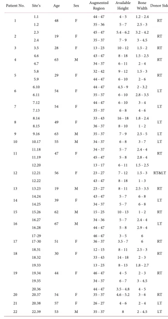
premolar. The incision was extended through the retromolar region to the ra-mus. An anterior oblique release incision was made at the first premolar and ex-tended to the vestibular depth. This flap exposed the left augmented site (teeth 36 and 37 region), and the donor site of the bone block, It also allowed visualiza-tion of the lateral and inferior border of the mandible, the buccal shelf and the mental neurovascular bundle. The length (posterior-anterior) of the bone block, its width (superior-inferior) was determined and done by three complete osteo-tomies; posterior, anterior, and inferior (Figure 2(a)) with Micro Saw disc (Frios Micro Saw, DENTSPLY). The superior (crestal) edge was perforated with small holes by small round bur in a straight handpiece, and the determined the thick-ness of the bone block.
The block harvest was completed by straight osteotome that was malleated along the superior holes. The block was carefully released and obtained to avoid injury to inferior alveolar neurovascular bundle. The donor site was lifted to spontaneous healing.
2.3. The Wedge Preparation
The wedge preparation was done by multiple splitting of the harvested bone block. At the present case the bone block splitting was performed in its longitu-dinal axis, the firsts plit yielded two thinner bone blocks, and further splitting at the same axis gave 4 thin bone blocks from the original bone block (Figure 2(b) to Figure 2(d)). Further transverse splitting of the four thin bone blocks gave 8 - 10 thin bone blocks and each is one is called a bone wedge (Figure 2(e) and Figure 2(f)). In general we can make the splits of the original block at its trans-verse axis, and receive four thick bone blocks. Further splitting of those blocks at their long axis can give 8 - 10 thin bone wedges (Figure 2(g) to Figure 2(j)).
2.4. Recipient Site
DOI: 10.4236/ojst.2018.86021 223 Open Journal of Stomatology
Figure 2. WT, the donor site and the wedge preparation. (a) Bone block
DOI: 10.4236/ojst.2018.86021 224 Open Journal of Stomatology
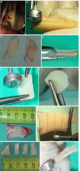
Figure 3. WT, The recipient site. (a) Grooves are created by height
speed, low speed or piezoelectric. (b) Three grooves were created at the left side.
grooves is limited by its distance from the inferior alveolar nerve that can be measured on the dental CT scan. In general the groove should be through and through bucco-lingually, and as deep as possible. The role of the groove in this technique is retain biologically and mechanically the bone wedge.
2.5. The Augmentation Procedure
Try-in of the bone wedges into the grooves at the recipient bed, and adaptation of a bone wedge for each groove. Thereafter one adapted wedge is inserted and taped into one groove using flat edge cylindrical instrument and hummer (Figure 4(a)). It is extremely important to check the stability of each wedge by trying to extract it out from the groove. Unstable wedge should be removed and changed by a stable one. The next step is trimming of sharp edges of each wedge to prevent trauma to the soft tissue overlying the augmentation (Figure 4(b) and Figure 4(c)).
Multiple bone compartments are achieved from the above stages, (Figure 4(d)). The next step is the filling of those compartments with allograft bone substitute (Miner-0ss, BioHorizons) (Figure 4(e) and Figure 4(f)). The final product is the planned bone augmentation volume (Figure 4(g)), that subse-quently was covered with resorbable collagen membrane (Geistlich Bio-Gide) (Figure 4(h)). The final step is tension free closure of the flap (Figure 4(i)). Free buccal fat pad graft may be used to enhance the closure of the flap.
DOI: 10.4236/ojst.2018.86021 225 Open Journal of Stomatology
Figure 4. WT, Bone augmentation. (a) Inserting and tapping of the wedges inside the grooves.
(b) Trimming of sharp edges. (c) Checking the stability is crucial. (d) Bone compartments at the recipient site. (e) Bone filler allograft. (f) Filling the bone compartments with allograft par-ticles. (g) The final bone volume. (h) Resorbable membrane.(o) Primary soft tissue closure.
3. Case Presentations
3.1. Case 1
A 45-year-old woman was referred to our department to augment atrophic ridges at the anterior and left posterior mandible.
DOI: 10.4236/ojst.2018.86021 226 Open Journal of Stomatology
Figure 5. Follow-up 2 weeks. (a) Clinical view; (b) The panoramic view demonstrates one
do-nor site and two recipient site; (c) to (e) CBCT four months after the surgery, nice bone gain.
Figure 6. Reentry 4 months. Nice bone gain: (a) RT side; (b) LT side; (c) and (d) Implants
[image:10.595.209.537.443.695.2]DOI: 10.4236/ojst.2018.86021 227 Open Journal of Stomatology
Figure 7. Follow up. (a) and (b): Crowns rehabilitation; (c) to (e): Panoramic radiograph
and clinical view 36 months after the surgery.
left posterior teeth (43 - 33 and 35, 36) teeth 34 and 44 were with poor prognosis (Figure 8(a) to Figure 8(c)). CBCT was performed and demonstrated the bone deficit in height and width at the anterior and left mandible. (Figure 8(d) and Figure 8(e)).
She was treated in two stages. At the first stage FWT was performed to aug-ment the anterior and left mandibular region.
Under general anesthesia, the bone block was harvested from the left retro-molar area (the same surgical site), the bone block was split to achieve multiple bone wedges (Figure 8(f) to Figure 8(i)). The recipient sites were prepared by creating grooves, and thereafter 7 bone wedges were inserted into the grooves in a stable position, and trimmed to smooth their sharp edges. Several bone com-partments were achieved (Figure 8(j) to Figure 8(l)), and filled with particulate allograft bone substitute. A final bone volume was achieved (Figure 8(m)), and then covered with resorbable membrane (Figure 8(n)). The recipient sites were closed primarily and tension free (Figure 8(o)). Temporary bridge based on teeth 34 and 44 was performed. The healing process was uneventful during the follow up period.
DOI: 10.4236/ojst.2018.86021 229 Open Journal of Stomatology
Figure 8. Case 1. (a) to (e): Clinical and radiographic view. (f) to (i): Bone block harvest
and preparation of the bone wedges. (j) to (o): FWT bone augmentation anterior and left mandible. (p) to (r): CBCT 4 months after bone grafting. (s) to (v): reentry and implants insertion 4 months after the augmentation surgery. (w): radiographic view-follow up. (x) to (y): Crowns Rehabilitation. (z): 48 months-follow-up.
the new bone mass (Figure 8(s)), and 6 implants were inserted (Figure 8(t) to Figure 8(u)). Immediate loading was performed over the anterior implants (Figure 8(v)).
All the inserted implants were successfully osseointegrated (Figure 8(w) and Figure 8(x)) and the final rehabilitation was performed after 3 months later (Figure 8(y)). This case was followed for 48 months (Figure 8(z)).
3.2. Case 2
DOI: 10.4236/ojst.2018.86021 231 Open Journal of Stomatology
Figure 9. (a) to (s) Case 2. (a) and (b) Clinical view-anterior maxilla. (c) to (e): CBCT
anterior maxilla. (f) to (g): FWT bone augmentation. (h) to (k): Clinical and radiographic view-follow-up four months. (m): Reentry 4 months, nice bone volume. (n) and (p): The drilling for the implants was performed inside the bone wedges. (q): 4 implants were placed in the recipient site. (r) and (s): Clinical and radiographic view at 4 months after the reentry. (t) to (u): Temporary rehabilitation follow up, 6 months after implants inser-tion.
DOI: 10.4236/ojst.2018.86021 232 Open Journal of Stomatology the drilling through those wedges. Teeth 14 and 13 were extracted and particu-late allograft bone substitute was used to preserve their sockets. At this stage 4 implants were placed at the anterior augmented region with immediate loading (Figures 9(q)-(s)).
At the third stage, additional 4 implants were placed; 3 at the right maxilla and one implant at the location of tooth 23. Four months later the patient was re-ferred to her dentist for fixed prosthesis over the implants (Figures 9(t)-(u)).
4. Results
4.1. Clinical Outcomes
Bone augmentation with cortical bone wedges was performed in 39 sites in 22 patients (15 women, 7 men; mean age 47 years; range 19 to 67 years). The heal-ing process was uneventful. The donor site for the bone block, the retromolar area, healed very well without significant complications. Extra oral edema was resolved during 7 to 14 days after the surgery. Although in ten patients a tempo-rary post-operative lower lip hypoesthesia was noted, it was resolved completely after 3 months. No incidence of permanent sensory deficit was recorded. Spon-taneous regeneration of the donor sites was observed during the follow-up pe-riod without filling with bone substitutes at the surgery time.
In 21 patients the recipient sites healed very well, and the bone augmentations were maintained without wound dehiscence. In one patient, partial breakdown of the wound occurred, and the majority of the augmented bone was lost; this patient had completed treatment with nerve transposition.
Four months after the augmentation surgery, in 21 patients, clinical evalua-tion of the recipient sites revealed new hard tissue volume and good ridge con-tour. The CBCTs showed that good bone volume was obtained, and the bone gain was 4 to 8 mm horizontally and 3 - 6 mm vertically (Table 2).
The second surgery that was performed for implant insertion revealed a new and good bone volume, with excellent integration of the bone wedges in the re-cipient site.
114 implants were inserted of adequate lengths “10 - 16 mm” and diameters “3.3 - 4.2 mm” (Table 2). Further follow-up of the augmentation sites and the implants revealed stable outcomes. The mean follow-up period was 32 months.
4.2. Histologic Findings
DOI: 10.4236/ojst.2018.86021 233 Open Journal of Stomatology 3.75 - 4.2 11.5 - 13
2 3 3 - 5
3 - 5 2 - 3
2 - 3 5.8
5.9 5
3.75 10 - 11.5
10 - 11.5 3
2 2 - 6
2 - 2.5 3 - 5
3 - 4 6.10
6.11 6
3.75 11.5 - 13
10 - 11.5 4
3 2 - 5
3 - 6 3 - 6
3 - 8 7.12 7.13 7 3.75 13 11.5 4 2 2 - 4
3 - 4 2 - 3
2 - 6 8.14
8.15 8
3.75 10 - 11.5
2 2 - 5
3 - 5 9.16
9
4.2 11.5 - 13
3 2 - 3
3 - 8 10.17 10 4.2 4.2 10 10 3 2 2 - 3
2.5 - 3 4 - 5
5 11.18 11.19 11 3.75 3.75 4.2 10 - 13
11.5 - 13 11.5 - 13 4
4 3 4 - 7
4 - 6 3 - 7 2.5 - 4.5
2.5 - 4.5 3 - 3 12.20
12.21 12.22 12
3.75 11.5 - 13
4 6
2 - 4 13.23
13
3.75 3.75 10 - 11.5
10 - 11.5 4
3 1 - 2
2 - 3 5 - 6
3 - 5 14.24
14.25 14
3.3 - 3.75 13
6 4 - 6
3 - 5 15.26
15
3.75 3.75 10
10 - 11.5 3
3 2 - 3
2 - 3 4 - 6
3 - 5 16.27
16.28 16
4.2 4.2 8 - 10
8 - 10 2
2 2
2 5 - 7
5 - 7 17.29
17.30 17
3.75 - 4.2 3.75 11.5 - 13
13 3
4 4 - 5
3 - 4 3 - 5
2 18.31 18.32 18 3.75 3.75 3.75 13
8 - 11.5 10 - 11.5 4
2 4 3 - 4
4 - 6 3 - 5 4 2 4 19.33 19.34 19.35 19 4.2 4.2 8 - 10
8 - 10 3
2 2 - 3
2 - 3 4 - 6
4 - 6 20.36 20.37 20 3.75 10 2 3 - 5
5 - 7 21.38
21
3.75 10 - 11.5
3 1 - 2
3 - 6 22.39
[image:17.595.206.538.90.735.2]DOI: 10.4236/ojst.2018.86021 234 Open Journal of Stomatology
Figure 10. (a)-(c) Histological examination. (a) Clinical view, wedge biopsy. (b) CBCT
view of the site of the wedge biopsy. (c) The microscopic view of the bone wedge was captured at 20× magnification, the wedge is obvious at the center of the figure.
The histologic specimen of the bone wedge revealed osteocytes inside the bone wedge, osteoblasts and osteoclast in its periphery (Figure 10(c)). Those findings may indicate the vitality and remodeling of the graft.
5. Discussion
Autogenous bone grafts have been used many years for ridge augmentation and still considered the gold standard. Intraoral donor sites, mandibular symphysis and ramus are widely used. Extraoral donor sites are also used, and they are combined with major disadvantages that include the morbidity of the donor site, the high treatment costs, and high resorption rates [11]-[17].
Retromolar/ramus area is used as donor site, and the majority of the bone block that obtained is a cortical bone. Pikos in 2005 stated that one donor site can provide adequate bone volume for three-tooth segment, and can augment 3 - 4 mm as horizontal or vertical bone augmentation [41].
If extensive bone graft is required for one or more sites in the same mouth, then it may be necessary first to harvest simultaneously bilaterally from the ra-mus area and from the symphysis, or it may be necessary to make multiple aug-mentation of the same site. Schwarts reported the use of multitier technique for such cases. In addition some surgeons may use extraoral donor sites for exten-sive or multiple sites augmentations [42].
Among the major concerns in the bone block augmentation, two are impor-tant. First, bone block dislodgment during the implants insertion [43], and second, the presence of connective tissue layer between the block graft and the recipient bony site [44].
DOI: 10.4236/ojst.2018.86021 235 Open Journal of Stomatology The grooves that are prepared at the recipient site by the wedge have several functions that include: 1) mechanical retention of the cortical bone wedge so there is no need for fixation materials like screws, and in this way the hazards of hardware infection and expenses can be eliminated. 2) biological retention of the cortical bone wedge, and this is because the grooves are a kind of recipient site decortication, and the injury to the blood vessels can enhance angiogenesis and revascularization of the thin bone wedge in one hand, and in the other hand can accelerate the regional acceleratory phenomenon which have an important func-tion in the healing of the operated organs. It is well documented in the relevant literature that the success of bone grafting procedures depends mainly on the amount of revascularization (quality and intensity).
De Marco et al. in 2005 reported that several vascular sprouts proliferated to-ward the graft by the third day, and were demonstrated at the graft periphery. Revascularization was more intense in the area near the perforation of the reci-pient bed. Those findings may explain the integration the thin bone wedges in the retention grooves at the recipient bed, and this may happened due to the wide openings of the blood vessels when preparing the grooves at the recipient bed. Upon the histologic examinations from the bone wedges that were per-formed 4 months after the augmentation: Osteocytes were visible inside the wedge and indicates its vitality. In addition the presence of osteoclasts and os-teoblasts at the periphery of the wedge is an indicator of the graft remodeling.
vas-DOI: 10.4236/ojst.2018.86021 236 Open Journal of Stomatology and tension free closure of the recipient site [45].
6. Conclusion
The cortical bone wedge technique biological rational is to create multiple auto-genic bone compartments that filled with alloauto-genic bone particles. This combi-nation can augment multiple sites with intraoral autogenous bone blocks, and reduce the need for extraoral donor site. The wedge-groove unit may enhance revascularization of the bone graft and improve the graft survival.
Acknowledgements
Thanks to Doctor Abu Subeh Abir for her technical support.
Conflict of Interest
Declare that there is no financial interest or any conflict of interest.
References
[1] Chiapasco, M., Casentini, P. and Zaniboni, M. (2009) Bone Augmentation Proce-dures in Implant Dentistry. The International Journal of Oral & Maxillofacial Im-plants, 24, 237-259.
[2] Esposito, M., Grusovin, M.G., Coulthard, P. and Worthington, H.V. (2006) The Ef-ficacy of Various Bone Augmentation Procedures for Dental Implants: A Cochrane Systematic Review of Randomized Controlled Clinical Trials. The International Journal of Oral & Maxillofacial Implants, 21, 696-710.
[3] Rabelo, G.D., de Paula, P.M., Rocha, F.S., et al. (2010) Retrospective Study of Bone Grafting Procedures before Implants Placement. Implant Dentistry, 19, 342-350. https://doi.org/10.1097/ID.0b013e3181e416f9
[4] Haggerty, C.J., Vogel, C.J. and Fisher, G.R. (2015) Simple Bone Augmentation for Alveolarridge Defects. Oral and Maxillofacial Surgery Clinics of North America, 27, 203-226. https://doi.org/10.1016/j.coms.2015.01.011
[5] Boyne, P.J. and Herdford, A.S. (2001) An Algorithm for Reconstruction of Alveolar defects before Implant Placement. Oral and Maxillofacial Surgery Clinics of North America, 13, 533-541.
[6] Jensen, S.S. and Terheyden, H. (2009) Bone Augmentation Procedures in Localized Defects in the Alveolar Ridge: Clinical Results with Different Bone Grafts and Bone-Substitute Materials. The International Journal of Oral & Maxillofacial Im-plants, 24, 218-236.
DOI: 10.4236/ojst.2018.86021 237 Open Journal of Stomatology https://doi.org/10.1016/S0300-9785(86)80084-9
[12] Cricchio, G. and Lundgren, S. (2003) Donor Site Morbidity in Two Different Ap-proaches to Anterior Iliac Crest Bone Harvesting. Clinical Implant Dentistry and Related Research, 5, 161-169. https://doi.org/10.1111/j.1708-8208.2003.tb00198.x [13] Kline Jr., R.M. and Wolfe, S.A. (1995) Complications Associated with the
Harvest-ing of Cranial Bone Grafts. Plastic and Reconstructive Surgery, 95, 5-13. https://doi.org/10.1097/00006534-199501000-00002
[14] Frodel Jr., J.L., Marentette, L.J., Quatela, V.C. and Weinstein, G.S. (1993) Calvarial Bone Graft Harvest. Techniques, Considerations, and Morbidity. Archives of Oto-laryngology—Head & Neck Surgery, 119, 17-23.
https://doi.org/10.1001/archotol.1993.01880130019002
[15] Restoy-Lozano, A., Dominguez-Mompell, J.L., Infante-Cassio, P., Lara-Chao, J. and Lopez-Pizarro, V. (2015) Calvarial Bone Grafting for Three-Dimensional Recon-struction of Severe Maxillary Defects: A Case Series. The International Journal of Oral & Maxillofacial Implants, 30, 880-890. https://doi.org/10.11607/jomi.3627 [16] Chen, Y.C., Chen, C.H., Chen, P.L., Huang, I.Y., Shen, Y.S. and Chen, C.M. (2006)
Donor Site Morbidity after Harvesting of Proximal Tibia Bone. Head & Neck, 28, 496-500. https://doi.org/10.1002/hed.20452
[17] Nkenke, E., Weisbach, V., Winckler, E., Kessler, P., Schultze-Mosgau, S., Wiltfang, J. and Neukam, F.W. (2005) Morbidity of Harvesting of Bone Grafts from the Iliac Crest for Preprosthetic Augmentation Procedures: A Prospective Study. Interna-tional Journal of Oral and Maxillofacial Surgery, 33, 157-163.
https://doi.org/10.1054/ijom.2003.0465
[18] Khoury, F. (1999) Augmentation of the Sinus Floor with Mandibular Bone Blocks and Simultaneous Implantation: A 6-Year Clinical Investigation. The International Journal of Oral & Maxillofacial Implants, 14, 557-564.
[19] Misch, C.M. (1996) Ridge Augmentation Using Mandibular Ramus Bone Grafts for the Placement of Dental Implants: Presentation of a Technique. Practical Periodon-tics and Aesthetic Dentistry, 8, 127-135.
[20] Mish, C.M. (1997) Comparison of Intraoral Donor Site for Inlay Grafting Prior to Implant Placement. The International Journal of Oral & Maxillofacial Implants, 12, 767-776.
[21] Schwartz-Arad, D., Levin, L. and Sigal, L. (2005) Surgical Success of Intraoral Au-togenous Block Onlay Bone Grafting for Alveolar Ridge Augmentation. Implant Dentistry, 14, 131-138. https://doi.org/10.1097/01.id.0000165031.33190.0d
DOI: 10.4236/ojst.2018.86021 238 Open Journal of Stomatology
[25] Clavero, J. and Lundgren, S. (2003) Ramus or Chin Grafts for Maxillary Sinus Inlay and Local Onlay Augmentation: Comparison of Donor Site Morbidity and Compli-cations. Clinical Implant Dentistry and Related Research, 5, 154-160.
https://doi.org/10.1111/j.1708-8208.2003.tb00197.x
[26] Nkenke, E., Radespiel-Tröger, M., Wiltfang, J., Schultze-Mosgau, S., Winkler, G. and Neukam, F.W. (2002) Morbidity of Harvesting of Retromolar Bone Grafts: A Prospective Study. Clinical Oral Implants Research, 13, 514-521.
https://doi.org/10.1034/j.1600-0501.2002.130511.x
[27] Nkenke, E., Schultze-Mosgau, S., Kloss, F., Neukam, F.W. and Radespiel-Tröger, M. (2001) Mobidity of Harvesting of Chin Grafts: A Prospective Study. Clinical Oral Implants Research, 12, 495-502. https://doi.org/10.1034/j.1600-0501.2001.120510.x [28] Widmark, G., Andersson, B., Andrup, B., Carlsson, G.E., Ivanoff, C.J. and Lindvall,
A.M. (1998) Rehabilitation of Patients with Severely Resorbed Maxillae by Means of Implants with or without Bone Grafts. A One Year Follow-Up Study. The Interna-tional Journal of Oral & Maxillofacial Implants, 13, 474-482.
[29] Cammack, G.V., Nevins, M., Clem, D.S., Hatch, J.P. and Mellonig, J.T. (2005) His-tologic Evaluation of Mineralized and Demineralized Freeze-Dried Bone Allograft for Ridge and Sinus Augmentations. The International Journal of Periodontics and Restorative Dentistry, 25, 231-237.
[30] Simon, M., Fontana, F., Rasperini, G. and Maiorana, C. (2007) Vertical Ridge Aug-mentation by Expanded-Polytetrafluoroethylene Membrane and a Combination of Intraoral Autogenous Bone Graft and Deproteinized Anorganic Bovine Bone (Bio Oss). Clinical Oral Implants Research, 18, 620-629.
https://doi.org/10.1111/j.1600-0501.2007.01389.x
[31] Koll, A., Handschel, J., Drescher, W., Rothamel, D., Kloss, F., Blessmann, M., Heil-and, M., Wolff, K.-D. and Smeets, R. (2012) Current Trends and Future Perspective of Bone Substitute Materials-From Space Holders Materials to Innovative Biomate-rials. Journal of Cranio-Maxillo-Facial Surgery, 40, 706-718.
[32] Gomes, K.U., Carlini, J.L., Biron, C., Rapoport, A. and Dedivitis, R.A. (2008) Use of Allogenic Bone Graft in Maxillary Reconstruction for Installation of Dental Im-plants. Journal of Oral and Maxillofacial Surgery, 66, 2335-2338.
https://doi.org/10.1016/j.joms.2008.06.006
[33] Le, B., Burstein, J. and Sedghizadeh, P.P. (2008) Cortical Tenting Grafting Tech-nique in Severely Atrophic Alveolar Ridge for Implant Site Preparation. Implant Dentistry, 17, 40-50. https://doi.org/10.1097/ID.0b013e318166d503
[34] Khojasteh, A., Behnia, H., Shayesteh, Y.S., Morad, G. and Alikhasi, M. (2012) Loca-lized Bone Augmentation with Cortical Bone Blocks Tended over Different Parti-culate Bone Substitutes: A Retrospective Study. The International Journal of Oral & Maxillofacial Implants, 27, 1481-1493.
DOI: 10.4236/ojst.2018.86021 239 Open Journal of Stomatology
[40] LaTenta, G.S., MaCarthy, J.C., Breitbant, A.S., et al. (1989) The Role of Rigid Skelet-al Fixation in Bone-Graft Augmentation of the CraniofaciSkelet-al Skeleton. Plastic and Reconstructive Surgery, 84, 578-588.
[41] Pikos, M.A. (2005) Mandibular Block Autografts for Alveolar Ridge Augmentation.
Atlas of the Oral and Maxillofacial Surgery Clinics, 13, 91-107. https://doi.org/10.1016/j.cxom.2005.05.003
[42] Schwarts, A.D. and Levin, L. (2007) Multitier of Harvesting Technique for Bone Augmentation Using Intraoral Autogeneous Bone Blocks. Implant Dentistry, 16, 5-12. https://doi.org/10.1097/ID.0b013e3180327595
[43] Proussaefs, P. and Lozada, J. (2005) The Use of Intraorally Harvested Autogenous Block Grafts for Vertical Alveolar Ridge Augmentation: A Human Study. The In-ternational Journal of Periodontics and Restorative Dentistry, 25, 351-363.
[44] De Carvalho, P.S., Vasconcellos, L.W. and Pi, J. (2000) Influence of Bed Preparation on the Incorporation of Autogeneous Bone Grafts: A Study in Dogs. The Interna-tional Journal of Oral & Maxillofacial Implants, 15, 65-570.
[45] Kablan, F. and Laster, Z. (2014) The Use of Free Fat Tissue Transfer from the Buc-cal Fat Pad to Obtain and Maintain Primary Closure and to Improve Soft Tissue Thickness at Bone-Augmented Sites: Technique Presentation and Report of Case Series. The International Journal of Oral & Maxillofacial Implants, 29, e220-e231. https://doi.org/10.11607/jomi.te58