Development of Roller Ends Forced-Contact Model and
Cambering Technology for UCM Temper Mill (II)
——Development of Cambering Technology for UCM Temper Mill
Zhenhua Bai1, Xiaodong Shi1, Hongxin Si1, Linfang Han1, Ruibing Long1, Shoumin Wu2, Xiujun Li2, Dongdong Zhang1
1
School of Mechanical Engineering, State Key Laboratory of Metastable Materials Science and Technology, Yanshan University, Qinhuang Island, China
2
Thin Strip Co., Ltd., Baoshan Iron & Steel Co., Ltd., Shanghai, China E-mail: bai_zhenhua@yahoo.com.cn, sihongxin@126.com, xiaodong_shi@126.com
Received April 18, 2011; revised May 18, 2011; accepted May 25, 2011
Abstract
Roller ends forced-contact and overmuch roll consumption are the widespread problems in temper rolling process of thin strip for two-stand UCM temper mill. Fully thinking the equipment and technology charac-teristics of UCM temper mill, we took the newly-built 1220 UCM temper mill of Baosteel as the research object in this paper. A model of roller ends forced-contact and a calculation model of flatness for UCM tem-per mill are established after a great deal of site tracing and theoretical researches. On this basis, an optimal mathematical model of roll shape which is suited for UCM temper mill is developed. Working roll curve is the combination of cosine curve and high order curve. The cosine subentry is used to control edge wave, the high order curve subentry is used to control roller ends forced-contact. Furthermore, the chamfering curve of middle roller end is optimized. Those are the innovations. Through the above-mentioned technology, pres-sure distribution between rollers caused by the shift of middle roll becomes more homogeneous, prespres-sure peak disappeared, working life of roll is improved effectively as well. Relevant technologies have been used to the practice of 1220 UCM temper mill of Baosteel and have achieved good use effects, which is of further extending application value.
Keywords:UCM, Temper Mill, Forced-Contact, Roll Shape, Roll Consumption
1. Development of Cambering Technology
for UCM Temper Mill
1.1. Target of Cambering
The intermediate roll should have proper shift for im-proving strip shape in the process of temper rolling. But the shift of intermediate roll will make the pressure dis-tribution between rollers more uneven. Peak disdis-tribution will appear and cause uneven abrasion of rollers. Strip shape and surface quality will become worse. Roll con-sumption will increase sharply. In addition, the contact of working rolls outside the plate width will appear when thin and narrow strip is temper rolled. The forced-contact of working rolls will lead to that partial presetting rolling force is used to metal deformation and others cause the roller ends squashed which lead to the actual elongation
roll-ers caused by the shift of middle roll become more ho-mogeneous. Side effects such as peak are disappeared. Working life of roll is improved effectively [1].
1.2. Development of Cambering Model for UCM Temper Mill
From the metal deformation model, the strip shape of the first and second stand in exit can be expressed with the following formulas for two-stand UCM temper mill:
11i f h H L B T1 1i, i, , ,i 10,T20
(31)
21i f2 h2i, ,h1i 11i, ,B T20,T21
(32)
where h1i, h2i are the transverse distribution value of
strip exit thickness in the first and the second stand, Hi
is the transverse distribution value of strip entry thick-ness, Li is the transverse distribution value of length
and used to express the incoming profile, B is the width
of strip.
Similarly, from the model for elastic deformation of rolls mentioned in 2.2, the transverse distribution value of strip exit thickness in the first and second stand h1i,
2i
h , the pressure between rollers q1mwi, q1mbi, q2mwi,
2mbi
q and elongation can be expressed with the fol-lowing formulas [2]:
1i 3 10, 20, ,1 1m, 1w, 1wi, 1mi, 1bi, i, 11i, 1
h f T T P S S D D D H (33)
2i 4 20, 21, ,2 2m, 2w, 2wi, 2mi, 2bi, ,1i 21i, 2
h f T T P S S D D D h (34)
1mwi 5 10, 20, ,1 1m, 1w, 1wi, 1mi, 1bi, i, 11i, 1
q f T T P S S D D D H (35)
1mbi 6 10, 20, ,1 1m, 1w, 1wi, 1mi, 1bi, i, 11i, 1
q f T T P S S D D D H (36)
2mwi 7 20, 21, ,2 2m, 2w, 2wi, 2mi, 2bi, ,1i 21i, 2
q f T T P S S D D D h (37)
2mbi 8 20, 21, ,2 2m, 2w, 2wi, 2mi, 2bi, ,1i 21i, 2
q f T T P S S D D D h (38)
2
9 20, 21, ,2 2 , 2 , 2 , 2 , 2 , ,1 21, ,2
i i
m w wi mi bi i i i
i
H h
f T T P S S D D D h H
H
(39)
where q1mwi and q2mwi are the pressure between
in-termediate roll and working roll in the first and the sec-ond stand; q1mbi and q2mbi are the pressure between
intermediate roll and back-up roll in the first and the second stand; S1w, S2w, S1m and S2m are the
bend-ing force of workbend-ing roll and intermediate roll in the first and the second stand; D1wi, D1mi and D1bi are the
roll configuration distribution value of working roll, in-termediate roll and back-up roll in the first stand; D2wi,
2mi
D
and D2bi are the roll configuration distribution
value of working roll, intermediate roll and back-up roll in the second stand; 1 and 2 are the intermediate
roll’s shift value of the first and the second stand; T10, 20
T and T21 are the back tension, middle tension and front tension; P1 and P2 are the total rolling force of
the first and the second stand.
During the optimizing process of cambering, if the actual datas of Hi and Li existed, then the actual
datas should be used. Or the distribution of incoming crown can be considered as conic and proportion crown can be considered as 0.01 as a rule of thumb; the incom-ing profile is good and the value of Li is zero. The
back-up roll can be considered as plain barrelled roll, that is to say the value of D1bi and D2bi are all zero.
And then, after a simple analysis, for a specific rolling process of two-stand UCM temper mill, on condition that
the back-up roll is plain barrelled roll, if the rolling craft parameters P P T1, ,2 21,T20,T10,B , the bending force of
working roll and intermediate roll and the shift value of intermediate S1w,S2w,S1m,S2m, , 1 2 etc. are given,
21i
the transverse distribution value of front tension in exit, q1mwi,q1mbi,q2mwi,q2mbi the transverse distribution
value of pressure between rollers, the elongation can be expressed with roll profile parameters of working roll and intermediate roll uniformly after coupling Equation (31) to Equation (39).
21i f10 D1wi, D2wi, D1mi, D2mi
(40)
1mwi 11 1wi, 2wi, 1mi, 2mi
q f D D D D (41)
1mbi 12 1wi, 2wi, 1mi, 2mi
q f D D D D (42)
2mwi 13 1wi, 2wi, 1mi, 2mi
q f D D D D (43)
2mbi 14 1wi, 2wi, 1mi, 2mi
q f D D D D (44)
15 1wi, 2wi, 1mi, 2mi
f D D D D
ex-pression, the form of Equation (37) and Equation (38) are similar to Equation (39) and Equation (40)
Actually, according to the production characteristics of two-stand UCM temper mill, the working roll configura-tion curves and back-up roll configuraconfigura-tion curves of two stands are often designed to the same curve. And then, Equation (40) to Equation (45) as follows:
21i f16 Dwi, Dmi
(46)
1mwi 17 wi, mi
q f D D (47)
1mbi 18 wi, mi
q f D D (48)
2mwi 19 wi, mi
q f D D (49)
2mbi 20 wi, mi
q f D D (50)
21 wi, mi
f D D
(51) Based on field experiments and theoretical research, shown as Figure 3, the form of working roll
configura-tion curve is shown in the following Equaconfigura-tion (52) [3]:
1 cos 2 2w k
w w w
w w
x x
D x D a b c
L L
(52)
where Dw is the original working roll diameter, Lw is the face length of working roll, a is the crown value,
w
b is the cosine phase coefficient of working roll con-figuration curve, c is subentry coefficient of working
roll’s high order curve, kw is subentry index of working roll’s high order curve.
In Equation (52), the cosine subentry is used to control edge wave, the high order curve subentry is used to con-trol roll forced-contact. Obviously, it is easy to describe working roll configuration curve shown in Figure 3 and
Equation (52) if a b c k, , ,w w are given.
[image:3.595.310.537.77.200.2]Allow for the actual working ability of grinder, in practice, the intermediate roll configuration curve can be expressed with the following Equation (53) (as shown in
Figure 4):
2 2
2 2
z k
m z
z z
D x L l
D x x L l
D x L l
l
(54) where D is the original diameter of intermediate roll,
L is the face length of intermediate roll.
So, relevant roll profile parameters can be expressed with a b c k, , ,w w, , , l kz , therefore, Equation (46) to
Equation (51) can be expressed with Equation (55) to Equation (60) further.
21i f22 a b c k, , ,w w, , ,l kz
[image:3.595.309.536.227.363.2] (55)
Figure 3. The Schematic diagram of working roll curve.
Figure 4. The Schematic diagram of intermediate roll curve.
1mwi 23 , , ,w w, , ,z
q f a b c k l k (56)
1mbi 24 , , ,w w, , ,z
q f a b c k l k (57)
2mwi 25 , , ,w w, , ,z
q f a b c k l k (58)
2mbi 26 , , ,w w, , ,z
q f a b c k l k (59)
27 , , ,w w, , ,z
f a b c k l k
(60) In this way, on condition that the parameters of mental deformation model and roller system model such as roll-ing force and tension etc. are known, the optimizroll-ing ob-jective function of working roll profile and intermediate roll profile can be expressed with the following formulas for a single specification product and the equipment and production craft characters of UCM temper mill [4]:
min
1
1
2
2
1
, , , , , ,
s q
mw mw
mb mb
mw mw
mb mb
w w z
F X F X F X
X
g X k
g X k
g X k
g X k
X a b c k l k
[image:3.595.358.537.402.507.2]where is weighting coefficient, min is the
mini-mum elongation ruled by product program.
sF X is objective function of shape control,
21
21
21
max min
1, 2, ,
i i
s
F X i n
T
,
qF X is overall objective function of pressure be-tween rollers:
1 1 2 2
1 1 2 2
1 1 2 2
4
max , , ,
min , , ,
mw mb mw mw
q
mw mb mw mw
mw mb mw mw
G X G X G X G X
F X
G X G X G X G X
G X G X G X G X
.
1mwG X is control objective function of pressure be-tween intermediate roll and working roll in the first stand,
1mw 1mw 1mw
G X g X g X .
1mwg X is the indicator function of pressure’s degree of uniformity between intermediate roll and working roll in the first stand,
1 11
2 1
1 1 1
1 1 1
1 1 1 mw mw mw n n mw
mw n mwi mwi
i mw i
mwi i
n
g X q q
n
q
.
1mwg X is the indicator function of peak pressure be-tween intermediate roll and working roll in the first stand,
1 1
1 1 1
1 1
max min
mw mw
mw n mwi mwi
mwi i
n
g X q q
q
.
1mbG X is the target function of pressure control be-tween intermediate roll and back-up roll in the first stand,
1mb 1mb 1mb
G X g X g X .
1mbg X the indicator function of pressure’s degree of uniformity between intermediate roll and back-up roll in the first stand,
1 11
2 1
1 1 1
1 1 1
1 1 1 mb mb mb n n mb
mb n mbi mbi
i mb i
mbi i
n
g X q q
n
q
.
1mbg X is the indicator function of peak pressure be-tween intermediate roll and back-up roll in the first stand,
1 1
1 1 1
1 1
max min
mb mb
mb n mbi mbi
mbi i
n
g X q q
q
.
2mwG X is the target function of pressure control be-tween intermediate roll and working roll in the second stand, G2mw
X g2mw
X g2mw
X .
2mwg X is the indicator function of pressure’s degree
of uniformity between intermediate roll and working roll in the second stand [5],
2 22
2 2
2 2 2
1 2 1
2 1 1 mw mw mw n n mw
mw n mwi mwi
i mw i
mwi i
n
g X q q
n
q
.
2mwg X is the indicator function of peak pressure be-tween intermediate roll and working roll in the second
stand,
2
2
2 2 2
2 1
max min
mw mw
mw n mwi mwi
mwi i
n
g X q q
q
.
2mbG X is the target function of pressure control be-tween intermediate roll and back-up roll in the second stand, G2mb
X g2mb
X g2mb
X .
2mbg X is the indicator function of pressure’s degree of uniformity between intermediate roll and back-up roll in the second stand,
2 22
2 2
2 2 2
1 2 1
2 1 1 mb mb mb n n mb
mb n mbi mbi
i mb i
mbi i
n
g X q q
n
q
.
2mbg X is the indicator function of peak pressure
be-tween intermediate roll and back-up roll in the second
stand,
2
2
2 2 2
2 1
max min
mb mb
mb n mbi mbi
mbi i
n
g X q q
q
.where ksq is allowable transverse maximum peak value
between rolls, n is number of transverse strip element,
1mw
n is number of strip element between intermediate
roll and working roll in the first stand, n1mb is number
of strip element between intermediate roll and back-up roll in the first stand, n2mw is number of strip element
between intermediate roll and working roll in the second stand, n2mb is number of strip element between
1
min
1
1
2
2
, , , , , ,
m
j j j
j j
mwj mw
mbj mb
mwj mw
mbj mb
w w z
G X F X
X
g X k
g X k
g X k
g X k
X a b c k l k
(62)
where j is weighted coefficient of output, which is
depend on the portion of each specification output share in all output.
So, the comprehensive optimization of working roll configuration curve and intermediate roll configuration curve translate into seeking a suitable roll configuration curve parameters X
a b c k, , ,w w, , , l kz
, whichminimizes G X
.1.3. Application of Cambering Model in UCM Temper Mill
Working roll, intermediate roll and back-up roll are all flat roll at the beginning of putting into production of the newly-built 1220 UCM temper mill of Baosteel. The phenomenons which Elongation does not reach the stan-dard and strip shape is unqualified were often found in production. In order to solve the shape and mechanical property problems, relevant theories introduced in 3.2 are applied at the base of Section 2 and the working roll and back-up roll configuration curves are optimized. More-over, the new roll shape has been put into field operation in 2010, a significant effect have been received. Not only the strip shape has guaranteed, but also the mechanical property has the users’ request. At present, this roll shape has been adopted regularly by field as process planning. Relevant circumstances are introduced in details as fol-lows:
1.3.1. Cambering Scheme of 1220 Two-Stand UCM Temper Mill
Based on calculations, working roll adopts the roll con-figuration curve illustrated in Equation (63), intermediate roll adopts the roll configuration curve illustrated in Equation (64), back-up roll adopts flat roll [7].
56 5
65π2 D 1.82 10 1 cos
180 2
5.2 10 *
w w
b
b
x D x
l
x l
(63)
3.26
150
600 150
2*15*10 * 150
150
m
D x
D x x
D x
(64)
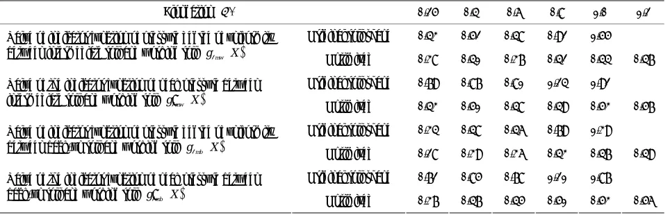
1.3.2. Introduction for Test Results of Field Comparison
To further analyses the roll shape reconstruction effect of the newly-built 1220 two-stand UCM temper mill of Baosteel, as a contrast, take the second stand as the ex-ample, working roll and intermediate roll adopt the roll configuration curve illustrated in Equation (63) and Equation (64) respectively, back-up roll adopts flat roll. 0.15 × 718 mm was choosed as specimen to do the forced-contact test (related equipments and process pa-rameters as shown in the following Table 1). The value
of contact width, actual rolling force and strip shape be-fore and after roll crown optimization were given though test. After the forced-contact test, the production of this specification proceeded with the elongation of 1.0% until roll changing. The length of rolling this moment was recorded in the following Table 3. The value of the
in-dicator function of pressure’s degree of uniformity and the indicator function of peak pressure are computed as well, shown in the following Table 4 [8].
It can be seen from Table 3 that the roll forced-contact
has been controlled effectively after roll shape was opti-mized. Slight roll forced-contact just appeared at the elongation of 1.2% (this moment, the product mechanical property has meet the users’ demand). When elongation increased to 0.4%, the roller ends forced-contact just appeared if original roll shape was adopted, and with the increase of elongation, the roller ends forced-contact become worse and worse, normal rolling was affected at last. In addition, it can be seen clearly from Table 3 that
the shape quality of strip improved greatly, measured maximum strip shape decreased apparently, the length of rolling increased greatly. Last, it can be seen from Table 3 that both the value of the indicator function of
[image:5.595.124.223.78.220.2]pres-sure’s degree of uniformity and the value of the indicator function of peak pressure decreased greatly. Combining
Table 3 and Table 4, it can be seen through field
con-trast tests that expected targets such as the control of roll forced-contact, the improvement of shape quality and the reducing of roll consumption all achieved.
2. Conclusions
Table 3. The value of contact width, actual rolling force and strip shape before and after roll crown optimization.
Elongation /% 0.25 0.4 0.6 0.8 1.0 1.2
Original roll shape 0 20.5 132 146 173 −
Contact width By/mm
Optimized 0 0 0 0 0 11
Original roll shape 1020 1750 4420 6540 9300 −
Actual rolling force PZ/kN
Optimized 1020 1680 3060 3920 4210 4630
Original roll shape 5.9 8.9 4.0 13.8 19.5 −
Measured maximum strip shape
max
I /I-Unit Optimized 3.2 4.1 3.8 4.2 4.3 4.6
Original roll shape − − − − 26 −
Length of rolling L/km
Optimized − − − − 145 −
Table 4. Contrast of the indicator function of pressure’s degree of uniformity and the indicator function of peak pressure before and after roll crown optimization.
Elongation /% 0.25 0.4 0.6 0.8 1.0 1.2
Original roll shape 0.43 0.52 0.48 0.92 1.55 −
Value of indicator function of pressure degree of uniformity
between intermediate roll and working roll g2mw X Optimized 0.38 0.41 0.37 0.42 0.44 0.47
Original roll shape 0.79 0.87 0.81 1.24 1.92 −
Value of the indicator function of peak pressure between
intermediate roll and working roll g2mw X Optimized 0.43 0.51 0.48 0.49 0.53 0.57
Original roll shape 0.34 0.48 0.46 0.79 1.39 −
Value of indicator function of pressure degree of uniformity
between back-up roll and working roll g2mb X Optimized 0.28 0.39 0.36 0.43 0.47 0.49
Original roll shape 0.72 0.85 0.78 1.21 1.87 −
Value of the indicator function of peak pressure between
back-up roll and working roll g2mb X Optimized 0.37 0.47 0.45 0.51 0.53 0.56
ends forced-contact and a computational model of flat-ness which is suited for UCM temper mill is established after lots of field tracing and theoretical research. More-over, on the basis of this, starting with the roll crown optimization of working rolls and intermediate rolls, strip shape, roll consumption and the management of roll forced-contact are considered as well. A mathematical model of rollcrown optimization which is suited for the working rolls and intermediate rolls of UCM temper mill is developed. Relevant technologies have been used to the practice of 1220 UCM temper mill of Baosteel. The pressure distribution between rollers caused by the shift of middle roll becomes more homogeneous. Side effects such as peak are disappeared. Working life of roll is im-proved effectively. This technology has achieved good use effects, which is of further extending application value.
3. Acknowledgements
Contract/grant sponsor and Grant Number:
1) Contract/grant sponsor: Hundred Excellent
Re-searchers Award Program of Department of Education of Hebei Province. Grant Number: CPRC018.
2) Contract/grant sponsor: Natural Science Foundation of Hebei Province (Surface Project). Grant Number: E2011203019.
3) Contract/grant sponsor: Natural Science Foundation of Hebei Province (Base Special Fund). Grant Number: 08B015.
4. References
[1] Z. H. Bai, “Development and Research of Shape Control Technology about Skin Mill,” Doctoral Dissertations, Yanshan University, Qinhuang Island, 2002.
[2] J. C. Lian and H. M. Liu, “Guage and Shape Control,” Weapon Industry Press, Beijing, 1995.
[3] Z. H. Bai, X. P. Kang and R. B. Long, “Practical Temper Rolling Force Model and Its Self Study Technology,” Steel, Vol. 43, No. 10, 2008, pp. 51-54.
[4] Z. H. Bai, Y. F. Jiang and X. D. Li, “Kiss between Roller Ends in Skin Rolling Process of Super Thin Strip,” Chi-nese Journal of Mechanical Engineering, Vol. 42, No. 8,
[image:6.595.59.541.288.443.2][5] Z. H. Bai and J. Yang, “Research on Shape Technique for Baosteel Planishing Mill,” Bao-Steel Technology, Vol. 1, 2003, pp. 48-51.
[6] Z. H. Bai, “Calculating Model of Rolling Parameters of Two-Stand Planishing Mill,” Journal of Iron and Steel Research, Vol. 18, No. 9, 2006, pp. 29-31.
[7] Z. H. Bai, X. P. Kang and S. M. Wu, “Shape Parameters
Online Setting of Two-Stand UCM Temper Mill,” Steel, Vol. 44, No. 5, 2009, pp. 39-43.
![Figure 3tion curve is shown in the following Equation (52) [3]:](https://thumb-us.123doks.com/thumbv2/123dok_us/9071605.403632/3.595.358.537.402.507/figure-tion-curve-shown-following-equation.webp)