doi:10.4236/ica.2011.23029 Published Online August 2011 (http://www.SciRP.org/journal/ica)
Self-Structured Organizing Single-Input CMAC Control
for De-icing Robot Manipulator
Thanhquyen Ngo1,2, Yaonan Wang1, Youhui Chen1, Zan Xiao1 1
College of Electrical and Information Engineering, Hunan University, Changsha, China 2
Faculty of Electrical Engineering, Ho Chi Minh City University of Industry, Ho Chi Minh, Vietnam E-mail: [email protected], [email protected]
Received June 1, 2011; revised June 22, 2011; accepted June 29, 2011
Abstract
This paper presents a self-structured organizing single-input control system based on differentiable cerebellar model articulation controller (CMAC) for an n-link robot manipulator to achieve the high-precision position tracking. In the proposed scheme, the single-input CMAC controller is solely used to control the plant, so the input space dimension of CMAC can be simplified and no conventional controller is needed. The structure of single-input CMAC will also be self-organized; that is, the layers of single-input CMAC will grow or prune systematically and their receptive functions can be automatically adjusted. The online tuning laws of sin-gle-input CMAC parameters are derived in gradient-descent learning method and the discrete-type Lyapunov function is applied to determine the learning rates of the proposed control system so that the stability of the system can be guaranteed. The simulation results of three-link De-icing robot manipulator are provided to verify the effectiveness of the proposed control methodology.
Keywords: Cerebellar Model Articulation Controller (CMAC), De-icing Robot Manipulator, Gradient-Descent Method, Self-Organizing, Signed Distance
1. Introduction
In general, robotic manipulators have to face various uncertainties in their dynamics, such as friction and ex-ternal disturbance. It is difficult to establish exactly mathematical model for the design of a model-based control system. In order to deal with this problem, the braches of current control theories are broad including classical control: neural networks (NNs) control [1-3], adaptive fuzzy logic control (FLCs) [4-6] or adaptive fuzzy-neural networks (FNNs) [7-9] etc. They are classi-fied as adaptive intelligent control based on conventional adaptive control techniques where fuzzy systems or neu-ral networks are utilized to approximate a nonlinear function of the dynamical systems. However, many adaptive approaches are rejected as being overly compu-tationally intensive because of the real-time parameter identification and required control design.
Fuzzy logic control (FLCs) has found extensive appli-cations for plants that are complex and ill-defined which is suitable for simple second order plants. However, in case of complex higher order plants, all process states are required as fuzzy input variables to implement state
feedback FLCs. All the state variables must be used to represent contents of the rule antecedent. So, it requires a huge number of control rules and much effort to create. To address these issues, single-input Fuzzy Logic con-trollers (S-FLC) was proposed for the identification and control of complex dynamical systems [10-12]. As a re-sult, the number of fuzzy rules is greatly reduced com-pared to the case of the conventional FLCs, but its control performance is almost the same as conventional FLCs.
input and output variables, Chiang and Lin [16] developed a CMAC network with a differentiable Gaussian recep-tive-field basis function and provided the convergence analysis for this network. The advantages of using CMAC over neural network in many applications were well documented [17-21]. However, in the above CMAC lit-eratures, the structure of CMAC cannot be obtained automatically. The amount of memory space is difficult to select, which will influence the learning and control schemes. Some self-organizing CMAC neural networks were proposed for structure adaptation [22-25]. In [22] and [23] a data clustering technique is used to reduce the memory size and a structural adaptation technique is developed in order to accommodate new data sets. However, only the structure growing mechanism is in-troduced and; the pruning mechanism was not discussed. In [24], a self-organizing hierarchical CMAC was intro-duced. The authors proposed a multilayer hierarchical CMAC model and used Shannon’s entropy measure and golden-section search method to determine the input space quantization. However, their approach is too com-plicated and lacks online real-time adaptation ability. Online adjusting suitable memory space of CMAC structure is our motivation. To address these issues, C. M. Lin, T. Y. Chen proposed self-organizing control system [25]. This control system does not require prior knowl-edge amount of memory space, the layers of CMAC will grow or prune systematically. However, the dimension of the input space of CMAC control system is reduced through a combination of sliding control model. Recently, to deal with the problem of the simplified input, B. J Choi, S. W. Kwak and B. K. Kim proposed the S-FLC [10-12] and its advantages which are mentioned above. Based on the S-FLC, several literatures developed sin-gle-input CMAC (S-CMAC) control system [26,27], which adopts two learning stages, namely, an offline learning stage and online learning stage. The disadvan-tage is that their derivative information is also not pre-served. So, M. F. Yeh and C. H. Tsai proposed differen-tiable standalone CMAC control system [28] to provided better system status in the learning control. In addition, the quantization of input space could be reduced while using the differentiable standalone CMAC. However, the disadvantages are that the structure of S-CMAC cannot be obtained automatically.
In this paper, we propose a novel self-structured orga-nizing single-input CMAC (SOSICM) control system for three-link De-icing robot manipulator to achieve the high-precision position tracking. This control system combines advantages of S-CMAC and it does not require prior knowledge of a certain amount of memory space, and the self-organizing approach demonstrates the prop-erties of generating and pruning the input layers
auto-matically. The developed self-organizing rule of S-CMAC is clearly and easily used for real-time systems. More-over, the developed system is solely used to control the plant and no conventional or compensated controller. The online tuning laws of CMAC parameters are derived in gradient-descent method.
This paper is organized as follows: System description is described in section 2. Section 3 presents SOSICM control system. Numerical simulation results of a three-link De-icing robot manipulator under the possible occurrence of uncertainties are provided to demonstrate the tracking control performance of the proposed SOSICM system in section 4. Finally, conclusions are drawn in section 5.
2. System Description
In general, the dynamic of an n-link robot manipulator may be expressed in the Lagrange following form:
,
M q q C q q q G q N (1) where are the joint position, velocity and acceleration vectors, respectively,
, , n
q q q R
n nM q R denotes the inertia matrix, C q q
, Rnxn
1
nx
N R
expresses the matrix of centripetal and Coriolis forces, is the gravity vector, represents the vector of exter-nal disturbance , friction term
nx1 G q R
l
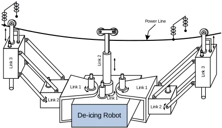
t f q , and un-modeled dynamics, is the torque vectors exerting on joints. In this paper, a new three-link De-icing robot ma-nipulator, as shown in Figure 1, is utilized to verify dy-namic properties are given in section 4.
1
mx
R
The control problem is to force
n,i
q t R 1, 2,
i m to track a given bounded reference input signal
Rndi
q t . Let be the tracking error vector as follows:
i e t
, 1, 2,
i di i
e q q i m (2) and the system tracking error vector is defined as
De-icing Robot Link 1 Link 1
Link 2 Link 2
Li
nk
3
Li
nk
3
Li
n
k 2
Link 1
[image:2.595.311.536.562.692.2]Power Line
1 2 1 1 1 2 1 1 2 0 0 0 0
0 0 0
0 0
, 1, 2, ,
i i i i i n ni i n
i i i i ni i
n
i i ni
k e
k e
k e
k e k e k e
i m (3)
where Kni Rn n
is the scaling factor matrix for the system tracking vector ei [ei ei ein1] Rn
, . 1, 2 ,
i m
Based on [10,11], the tracking error is trans-formed into a single variable, termed the signed distance
which is the distance from an actual state to the switching line as shown in Figure 2 for a 2-D input. The switching line is defined as follows:
n i R , m si d R
n
i R
1 2
1 2 1 0
n n
i n i i i
e e e e (4) where is a constant. Then, the signed dis-tance between the switching line and operating point
can be expressed by the following equation: 1 1 n n R n i R 1 2
1 ( 1) 2 2 1 1
2 2 2
1 2 1
1
n n
ni n n i i i
si
n
d
(5) According to the standalone CMAC control system is shown in Figure3. This control scheme provided better
i i 0 si d 0 si d si d ) , (i i
[image:3.595.73.288.79.182.2]0 i i
Figure 2. Derivation of a signed distance.
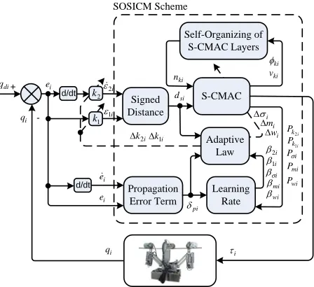
d/dt i si d i e + -di q i q i w i m i i 2 i 1 i q Signed Distance Adaptive Law Standalone Scheme 1 k 2 k i k1 i k2 S-CMAC
Figure 3. Block diagram of standalone CMAC control sys-tem.
control characteristics due to using the differentiable CMAC in the system. The advantage is that derivative information of input and output variables is preserved in learning process. In addition, the generalization error caused by quantization of input space could be reduced while using the differentiable CMAC.
Based on the standalone CMAC control system, we propose the SOSICM control system as shown in Figure 4, which combines advantages of standalone CMAC and it does not require prior knowledge of a certain amount of memory space. The self-organizing approach demon-strates the properties of generating and pruning the input layers automatically. The developed self-organizing rule of CMAC is clearly and easily used for real-time systems
3. Adaptive SOSICM Control System
3.1. Brief of the S-CMAC
An S-CMAC is proposed and shown in Figure 5. It is composed of an input, association memory, weight and output spaces. The signal propagation and the basic function in each space are expressed as follows:
1) Input space Ds; assume that each input state
vari-able dsi can be quantized into si discrete states and
that the information of a quantized state is regarded as region for each layer ki . Therefore, there exist
si
N
n th
1
N individual points on the si- axis. Figure 6
shows the case of si
d
10
N . Each activated state in each layer becomes a firing element, thus, the weight of each layer can be obtained. The Gaussian basic function for each layer is given as follows:
d/dt si d i e + -di q i q i w
mi
i i 2 i 1 i k1 i k2 i q Signed Distance S-CMAC Adaptive Law 2 k SOSICM Scheme Self-Organizing of S-CMAC Layers i ki ki v ki n 1 k Learning Rate Propagation Error Term
d/dt ei
i e pi wi P i P i k P 1 i k P2 mi P wi
mi
i
1i 2i
[image:3.595.312.536.485.690.2] [image:3.595.61.286.547.695.2]
k
n
w
m
o
k
n
s
D Input
Space Ds Output
Space O
Weight Memory Space W
Association Memory Space A
Target
+
-Figure5. Architecture of a single-input CMAC.
d1 d2 d3 d4 d7 d8 d9 d10
s1 s2 s3 s4 s5 s7 s8 s9 s10
dsi
-1 0 +1
Knot
State
Layer 1
Layer 2
Layer nki
d6
d5
s6
d0
Figure6. Block division of CMAC with Gaussian basic func-tion.
22
( ) exp ,
1, 2, , , 1, 2, ,
si ki
ki si
ki
ki
d m
d
i m k
n
(6)
where ki represents the kth layer of the input dsi w
the mean mki a the variance ki
ith
nd .
2) Output space O: The output of S-CMAC is the al-gebraic sum of the firing element with the weight mem-ory, and is expressed as
1
ki
n
i ki ki ki k
a w d
sin
(7) where denotes the weight of the kth layer,
is the index indicating whether the ithmemory element is addressed by the state involving
ki
w
dsi
,ki ki
a a k1, 2, ki
si. Since each state addressed exactly ki memory elements, only those addressed s are
one, and the others are zero. d
m aki,
The block diagram in Figure 3, in which only the S-CMAC plays a major role in the control process, thus to have a trade-off between the desired performance and the computation loading we must choose a reasonable number of layers. However, if the number of layers is
chosen too small, the learning performance may be in-sufficient to achieve a desired performance. Otherwise, if the number of layers is chosen too large, the calculation process is too heavy, so it is not suitable for real-time applications. To deal with this problem, a self-structured organizing S-CMAC is proposed includes structure and parameter learning as shown in Figure4.
3.2. Self-Structured Organizing S-CMAC
In this section, structural learning is necessary to deter-mine whether to add a new layer in association memory A depends on the firing strength of each layer for each incoming data
ki
n
ki R
si . If the firing strength
of each layer for new input data d
ki
n
ki R
si falls
outside the bounds of the threshold, then, SOSICM will generate a new layer. The self-structured organizing S-CMAC can be summarized as follows:
d
1) Calculate the firing strength of each layer for each input data
ki
n
ki R
si
2) Using Max-Min method is proposed for layer growing. Find
d in (6).
1
ˆ arg min , 1, 2,
ki
i ki si
k n
k d k
nki (8)
If
ˆ
i si
k d K
gi (9)
Here Kgi is a threshold value of adaptation with
0Kgi1. In our case and a new layer is generated.
0.1
gi
K
This means that for a new input data, the exciting value of existing basic function is too small. In this case, number of layers increased as follows:
1
ki ki
n t n t 1 (10) where ki is the number of layers at time t. Thus, a new
layer will be generated and then the corresponding pa-rameters in the new layer such as the initial mean and variance of Gaussian basic function in association mem-ory space and the weight memmem-ory space will be defined as
n
ki
n
m dsi (11) ˆ
ki
n ki
(12) 0
ki
n
w (13) Another self-structured organizing learning process is considered to determine whether to delete existing layer, which is inappropriate. A Max-Min method is proposed for layer pruning.
, 1, 2, ,
ki
ki ki
i v
MM k
n (14)
where vki
kiwki, Then, the minimum ratio of the kth component is defined as follows:1 arg min
ki
i
k n
k
MMki (15)
If
i ci
k
MM K (16) Here Kci is a predefined deleting threshold. In our
case and the i layer will be deleted.
This means that for an output data, if the minimum con-tribution of a layer is less than the deleting threshold, then this layer will be deleted.
0.03
Kci k th
3.3. On-Line Learning Algorithm
The central part of the learning algorithm for a SOSICM is how to choose the weight memory mean variance ki
,
ki
w mki,
of the Gaussian basic function. ni Are
the scaling factors of the error ei and the change of
error i, which will significantly affect the performance
of SOSICM. For achieving effective learning, an on-line learning algorithm, which is derived using the supervised gradient descent method, is introduced so that it can in real-time adjust the parameters of SOSICM. The energy function is defined as
k
e
i
E
2 21
2 2
i di i
E q q 1ei (17) According to the energy function (17) and the system structure in Figure 4, the error term to be propagated is given by
i i i
pi i
i i i
E E q
e q
i
i
q
(18)
where qi i represent the sensitivity of the plant with respect to its input. With the energy function the parameters updating law based on the normalized gradient descent method can be derived as follows
,
i
E
1) The updating law for the weight memory can be derived according to
kth
i i
ki wi wi
ki i ki
ki wi pi ki si
E E
w
w
a d
i w
(19)
where wi is positive learning rate for the output
weight memory the connective weight can be up-dated according to the following equation:
,
ki
w
1
ki ki ki
w t w t w (20) 2) The mean and variance of the Gaussian basic
function can be also updated according to
kth
2
2 2i i i
ki mi wi
ki i ki
si ki ki mi pi ki ki si
ki
E E
m
m m
d m
a w d
(21)
3
2 2i i i
ki i wi
ki i ki
si ki ki i pi ki ki si
ki
E E
d m
a w d
(22)
where mi, i are positive learning rates for the mean
and variance, respectively. The mean and variance can be updated as follows:
1
ki ki ki
m t m t m (23)
1
ki t ki t ki
(24) 3) Finally, the updating law for scaling factors can be derived as follows:
2
1
1
2 2 2
1 2 1
2
1
ki
i i i si
ni ni ni
ni i si ni
n
si ki
ni pi ki ki ki si
k ki
n n ni
n
E E d
k
k d k
d m
a w d
e
(25)
where mi is the learning rate, and it can be updated by
the following:
1
ni ni ni
k t k t k (26) The plant sensitivity qi i in (18) can be
calcu-lated if the plant model is exactly known. However, the plant model is unknown, so qi i can not obtained
in advance. To deal with this problem, in [28], a simple approximation of the error term of the system can be use as follows:
pi ei ei
(27)
3.4. Convergence Analysis
The update laws of Equations (19), (21), (22) and (25) require a proper choice of the learning rates wi, mi,
,
i
and ni in order to the convergence of the output
error is guaranteed; however, this is not easy which de-pends on each person’s experience. To train the S-CMAC effectively, the variable learning rates which guarantee convergence of the output error are derived in the following.
given by
1 2
2
i i
V k e k (28) Thus, the change of the Lyapunov due to the training process is obtained as
1 2
2
1 1
2
i i i i i
V k V k V k e k e k
(29) where ei
k1 is represented by [28]
1
T i
i i i i
i e k
e k e k e k e k P
P
i (30)
where ei represents the in the learning process, Pi
denotes a change of an adjustable parameters. Using Equation (18), we have ei Pi pi i e ki
Pi andi pi i i
P E P
pi pii Pi , where pi is the
learning rate for the parameter Pi.
Thus:
2 2 2 2 2 2 2 2 1 2 1 2 1 2 2i i i i
pi pi i pi pi i
i
i i i i
pi
i i
pi pi pi
i i i
V k e k e k e k
e k
e k P e k P
P e k P
(31)
If the learning rate pi is selected as:
2 20pi2 pi e ki i Pi (32) Then V ki
0, therefore V ki
1
V ki
, the Lyapunov stability (system stability) and the conver-gence of the tracking error could be guaranteed. In addi-tion, the optimal learning rate can be found for achieving faster convergence by taking the differential equation (31) with respect to pi and equals to zero. Finally, theop-timal learning rate can be determined as follows:
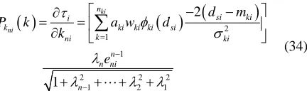
2 21
pi pi e ki i P
i (33)
where i Pi for Piw mki, ki,ki and , it can be
obtained as:
ni
k
i ,wi ki ki
ki
P k a
w
2
2 si ki i
mi ki ki ki
ki ki
d m
P k a w
m
3
22 si ki i
i ki ki ki
ki ki
d m
P k a w
2
1
1
2 2 2
1 2 1
2 1 ki ni n si ki i
k ki ki ki si
k ni ki n n ni n d m
P k a w d
k e
(34)4. Simulation Results
[image:6.595.322.538.79.143.2]A three-link De-icing robot manipulator as shown in Figure 1 is utilized in this paper to verify the effective-ness of the proposed control scheme. The detailed system parameters of this robot manipulator are given as: link mass , lengths angular posi-tions and displacement position
1, 2, 3( ) m m m kg
, ( ) q q rad
1,2 l l m ,
1 2 d3
m .The parameters for the equation of motion (1) can be represented as follow:
1121 1222 132331 32 33
M M M
M q M M M
M M M
2 211 1 1 2 2 1 2 1 1 1
2 2
3 2 2 2 2 1 2
9 4 1 4
2
2
M m l m c l l l l c s
m c l l c l l
2 2
22 1 4 2 2 3 2 4 3 1 1
2
M m l m l m l
23 32 3 2 2 M M m c l
33 3
M m
12 13 21 31 0
M M M M
1121 1222 132331 32 33
C C C
C q C C C
C C C
11 2 1 2 1 1 1
2 2
2 2 2 2 3 2 2 2 2 1 2 2 8
1 2 2 2
C m l l c s q
m s c l m s c l s l l q
2 2
21 1 2 2 2 2 2 3 2 2 2 2 2 2 1 2 1 C m s c l m s c l s l l q
d q
22 3 2 2 3
C m s l
23 2 3 2 2 2 C m s l
32 3 2 2 2 C m s l q
12 13 31 33 0
C C C C
1 2 21 2 2 2 1 12 2
23
3 1 2 1 2
c c l c l m g G q s s l m c l m g
m g (35)
where 3
qR and the shorthand notations
1 1 ,
2 sin 2
s q
1 3( ) m kg
are used.
For the convenience of the simulation, the nominal parameters of the robotic system are given as
2 2( ),
m kg m32.5(kg), 1
2 and
0.14( ),
l m
0.32( ),
l m g 9.8
m s2
0 0, d3
0 1, q2
and the initial condi-tions q1
0 0, q1
0 0,
. The desired reference trajectories are d1
2 0 0,
q d
q t
3 0 0
sin t , qd2
t cos
t , dd2 t cos
t , respectively.The most important parameters that affect the control performance of the robotic system are the external dis-turbance tl,the friction term f q
, which are injected into the robotic system, and their shapes are expressed as follows:
lt t
5sin 5t 5sin 5t 5sin 5t T
(36)
In addition, friction forces are also considered in this simulation and given as
1 1 2
3 3
20 0.8sgn 4 2sgn
4 2 sgn
T
2
f q q q q q
d d
(37)
In order to exhibit the superior control performance of the proposed SOSICM control system, the control sys-tem standalone CMAC is introduced in Figure 3 and examined in the mean time [28]. They are applied to control three-link De-icing robot manipulator and the same setting of SOSICM and standalone CMAC control system are chosen as follows: The inputs space of S-CMAC are ds1, ds2 and ds3, the mean and vari-ance of Gaussian basic functions are selected to cover the input space
1 1
k k k
w w w
1 1 1 1
; all initial weights
are set to zero, i.e., 1 2 3 . The parameter
0,
k1, 2,nki
in the switching line is one. For re-cording respective control performance, the mean-square-error of the position-tracking response is defined as:
2 11
, 1, 2, 3
T
i di i
j
mse
q
q j q j i
T
(38)where T is the total sampling instant, and i and di are the elements in the vector i and qdi. In this
paper, the numerical simulation results carried out by using Matlab software.
q q
Example 1: Consider the standalone CMAC control system is shown in Figure 3.
For the standalone CMAC control system, the pa-rameters are chosen such as: wi0.02, mi0.02,
0.02
i
, ni0.02,
2i 0.8
m
the initial value of Gaussian basic functions and scaling factors are defined as
1i 1.0,
m , m3i 0.6, m4i 0.4,
, m9i 0.6
5i 0.2,
m m6i0.0, m7i0.2, m8i0.4
10i 0.8,
m m11i1.0, ki 0.15, k1i0.5and k2i0.2
for k1, 2,,11, i1, 2, 3. The simulation results of standalone CMAC system, the responses of joint position and MSE are depicted Figures7(a)-(f), respectively.
0 2 4 6 8 10 12 14 16 18 2020
2 2
20 -2
-1 0 1
Time
P
o
si
ti
on l
ink
1(ra
d)
desired actual
(s)
(a)
0 2 4 6 8 10 12 14 16 18 20
-2 0 2
Time(s)
P
o
si
tio
n
lin
k
2
(
ra
d
)
desired actual
(b)
0 2 4 6 8 10 12 14 16 18 20
-2 0 2
Time(s)
D
is
ta
n
ce
l
ink 3 (m
)
actual desired
(c)
0 2 4 6 8 10 12 14 16 18 2020
0 0.2 0.4 0.6 0.8 1 1
Time(s)
M
S
E J
o
in
t
1
(
ra
d
)
(d)
0 2 4 6 8 10 12 14 16 18 2020
0 0.2 0.4 0.6 0.8 1 1
Time(s)
MSE
Jo
in
t 2
(
ra
d
)
(e)
0 2 4 6 8 10 12 14 16 18 2020
0 0.2 0.4 0.6 0.8 1
Time(s)
MS
E
J
o
in
t 3
(
m
)
(f)
[image:7.595.314.530.121.696.2]Example 2: Consider the proposed SOSICM control system is shown in Figure4.
For the proposed SOSICM control system, the pa-rameters are chose in the following:
2 2
1 ( )
pi pi e ki i Pi
for Piw mki, ki,ki and ni, and the initial values of system parameters are given
as , the inputs of S-CMAC 1 k
2
ki
n ds , ds2 and ds3 the mean and variance of Gaussian basic functions are selected to cover the input space
1 1
1 1
1 1
. The threshold value of Kgi is set as 0.1; Kci is set as0.01 for . The simulation results of the pro-posed SOSICM system, the responses of joint position, MSE and layer number are depicted in Figures 8(a)-(f) and (g), (h) and (k) respectively.
1, 2, 3
i
According to the simulation results as shown in Fig-ures7 and 8, the joint-position tracking responses of the proposed SOSICM system can be controlled to more closely follow desired reference trajectories than the standalone CMAC as shown in Figure 7 and Figures 8(a)-(c). Our proposed control system for each joint shows that the MSE in Figures8(d)-(f) is faster than the MSE in Figures7(d)-(f) and finally converges to 0.009, 0.015 and 0,019. Meanwhile the MSE of standalone CMAC is 0.032, 0.031 and 0.036 and number of layers of S-CMACs converge to three layers as shown in Fig-ures8(g), (h) and (k).
0 2 4 6 8 10 12 14 16 18 2020
-2 0 2
Time(s)
P
o
siti
o
n
lin
k
1
(
ra
d
)
desired actual
(a)
0 2 4 6 8 10 12 14 16 18 2020
-2 0 2
Time(s)
P
o
si
ti
on l
in
k 2 (ra
d)
desired actual
(b)
0 2 4 6 8 10 12 14 16 18 2020
-2 0 2
Time(s)
D
is
tnc
e l
ink
3 (m
)
desired actual
(c)
0 2 4 6 8 10 12 14 16 18 2020
0 0.2 0.4 0.6 0.8 1 1
Time(s)
M
S
E
Jo
in
t 1
(
rad
)
(d)
0 2 4 6 8 10 12 14 16 18 20
0 0.2 0.4 0.6 0.8 1 1
Time(s)
M
S
E
J
o
in
t
2
(
rad
)
(e)
0 2 4 6 8 10 12 14 16 18 2020
0 0.2 0.4 0.6 0.8 1 1.2 1.2
Time(s)
M
S
E
J
o
in
t 3
(
m
)
(f)
0 2 4 6 8 10 12 14 16 18 20
0 2 4 6 8 10 10
Time(s)
Lay
er
N
u
mb
er
C
M
A
C
1
(g)
0 2 4 6 8 10 12 14 16 18 2020
0 2 4 6 8 10
Time(s)
Lay
er
N
u
m
b
er
C
M
A
C
2
(h)
0 2 4 6 8 10 12 14 16 18 2020
0 2 4 6 8 10 10
Time(s)
L
aye
r nu
m
be
r
CM
A
C
3
(k)
Figure 8. Simulated position responses, MSEs and layer number of the SOSICM control system at joints 1, 2 and 3.
5. Conclusions
control the joint position of a three-link De-icing robot manipulator. In the SOSICM system, dynamical system is completely unknown and auxiliary compensated con-trol is not required in the concon-trol process. The online tuning laws of S-CMAC parameters are derived in gra-dient-descent learning method and the discrete-type Lyapunov function is applied to determine the variable optimal learning rates so that the stability of the system can be guaranteed. This paper has successfully devel-oped the SOSICM control system for a three-link De-icing robot manipulator not only requires low mem-ory with online structure and parameters tuning algo-rithm, but also the input space can be reduced through the signed distance. The simulation results of the pro-posed SOSICM system can achieve favorable tracking performance for three-link De-icing robot manipulator.
6. Acknowledgments
The authors would like to thank the editors and the re-viewers for their valuable comments.
7. References
[1] A. Vemuri, M. M. Polycarpou and S. A. Diakourtis, “Neural Network Based Fault Detection in Robotic Ma-nipulators,” IEEE Robotics Automation, Vol. 14, No. 2, 1998, pp. 342-348. doi:10.1109/70.681254
[2] W. Z. Gao and R. R. Selmic, “Neural Network Control of a Class of Nonlinear Systems with Actuator Saturation,”
American Control Conference, Boston, 2006, pp. 147-
156.
[3] Y. Zou, Y. N. Wang and X. Z. Liu, “Neural Network Robust H∞Tracking Control Strategy for robot
manipula-tors,” Applied Mathematical Modelling, Vol. 34, No. 7, 2010, pp. 1823-1838. doi:10.1016/j.apm.2009.09.026
[4] B.-S. Chen, H.-J. Uang and C.-S. Tseng, “Robust Track-ing Enhancement of Robot Systems IncludTrack-ing Motor Dynamics: A Fuzzy-Based Dynamic Game Approach,”
IEEE Transactions on Fuzzy Systems, Vol. 6, No. 4, 1998,
pp. 538-552. doi:10.1109/91.728449
[5] H.-X. Li and S.-C. Tong, “A Hybrid Adaptive Fuzzy Control for a Class of Nonlinear MIMO Systems,” IEEE
Transactions on Fuzzy Sysemstm, Vol. 11, No. 1, 2003,
pp. 24-34. doi:10.1109/TFUZZ.2002.806314
[6] S. Labiod, M. S. Boucherit and T. M. Guerra, “Adaptive Fuzzy Control of a Class of MIMO Nonlinear Systems,”
Fuzzy Set and Systems, Vol. 151, No. 1, 2005, pp. 59-77.
doi:10.1016/j.fss.2004.10.009
[7] Y. G. Leu, W. Y. Wang, and T. T. Lee, “Observe Based Direct Adaptive Fuzzy Neural Control for Non-Affine Nonlinear Systems,” IEEE Transactions on Neural
Net-works, Vol. 16, No. 4, 2005, pp. 853-861.
doi:10.1109/TNN.2005.849824
[8] R. J. Wai and Z. W. Yang, “Adaptive Fuzzy Neural
Net-work Control Design via a T-S Fuzzy Model for a Robot Manipulator Including Actuator Dynamics,” IEEE
Trans-actions on Systems, Man and Cybernnetics, Vol. 38, No.
5, 2008, pp. 1326-1346.
doi:10.1109/TSMCB.2008.925749
[9] C.-S. Chen, “Dynamic Structure Neural Fuzzy Networks for Robust Adaptive Control of Robot Manipulators,”
IEEE Transactions on Industrial Electronics, Vol. 55, No.
9, 2008, pp. 3402-3414. doi:10.1109/TIE.2008.926778
[10] B. J. Choi, S. W. Kwak and B. K. Kim, “Design of Sin-gle-Input Fuzzy Logic Controller and Its Properties,”
Fuzzy Sets and Systems, Vol. 106, No. 3, 1999, pp.
299-308. doi:10.1016/S0165-0114(97)00283-2
[11] B. J. Choi, S. W. Kwak and B. K. Kim, “Design and Sta-bility Analysis of Single-Input Fuzzy Logic Controller,”
IEEE Transactions on Systems, Man and Cybernnetics,
Vol. 30, No. 2, 2000, pp. 303-309.
doi:10.1109/3477.836378
[12] K. Ishaque, S. S. Abdullah, S. M. Ayob and Z. Salam, “Single Input Fuzzy Logic Controller for Unmanned Un-derwater Vehicle,” Journal of Intelligent and Robotic
Systems, Vol. 59, No. 3, 2010, pp. 87-100.
doi:10.1007/s10846-010-9395-x
[13] J. S. Albus, “A New Approach to Manipulator Control: The Cerebellar Model Articulation Controller,” Journal
of Dynamic Systems Measurement and Control, Vol. 97,
No. 3, 1975, pp. 220-227. doi:10.1115/1.3426922
[14] H. Shiraishi, S. L. Ipri and D. D. Cho, “CMAC Neural Network Controller for Fuel-Injection Systems,” IEEE
Transactions on Control Systems Technology, Vol. 3, No.
1, 1995, pp. 32-38. doi:10.1115/1.3426922
[15] S. Jagannathan, S. Commuri and F. L. Lewis, “Feedback Linearization Using CMAC Neural Networks,”
Auto-matica, Vol. 34, No. 3, 1998, pp. 547-557.
doi:10.1016/S0005-1098(97)00206-9
[16] C. T. Chiang and C. S. Lin, “CMAC with General Basis Functions,” Journal of Neural Networks, Vol. 9, No. 7, 1996, pp. 1199-1211.
doi:10.1016/S0005-1098(97)00206-9
[17] Y. H. Kim and F. L. Lewis, “Optimal Design of CMAC Neural-Network Controller for Robot Manipulators,”
IEEE Transactions on Systems, Man and Cybernnetics,
Vol. 30, No. 1, 2000, pp. 22-31.
doi:10.1109/5326.827451
[18] C. M. Lin and Y. F. Peng, “Adaptive CMAC-Based Su-pervisory Control for Uncertain Nonlinear Systems,”
IEEE Transactions on Systems, Man and Cybernnetics,
Vol. 34, No. 2, 2004, pp. 1248–1260.
doi:10.1109/TSMCB.2003.822281
[19] S. F. Su, T. Tao and T. H. Hung, “Credit Assigned CMAC and Its Application to Online Learning Robust Controllers,” IEEE Transactions on Systems, Man and
Cybernnetics, Vol. 33, No. 2, 2003, pp. 202-213.
doi:10.1109/TSMCB.2003.810447
doi:10.1016/j.neucom.2008.07.004
[21] Y. F. Peng and C. M. Lin, “Intelligent Hybrid Control for Uncertain Nonlinear Systems Using a Recurrent Cerebel-lar Model Articulation Controller,” IEEE Proceedings
Control Theory and Applications, Vol. 151, No. 5, 2004.
pp. 589-600. doi:10.1049/ip-cta:20040903
[22] J. Hu and F. Pratt, “Self-Organizing CMAC Neural Net-works and Adaptive Dynamic Control,” IEEE Interna-tional Symposium on Intelligent Control/Intelligent
Sys-tems and Semiotics, Cambridge, 1999, pp. 259-265.
[23] H. C. Lu and C. Y. Chuang, “Robust Parametric CMAC with Self-Generating Design for Uncertain Nonlinear Systems,” Neurocomputing, Vol. 74, No. 4, 2011, pp. 549-562. doi:10.1016/j.neucom.2010.09.001
[24] H. M. Lee, C. M. Chen and Y. F. Lu, “A Self-Organizing HCMAC Neural-Network Classifier,” IEEE Transactions
on Neural Networks, Vol. 14, No. 1, 2003, pp. 15-27.
doi:10.1109/TNN.2002.806607
[25] C. M. Lin and T. Y. Chen, “Self-Organizing CMAC Con-trol for a Class of MIMO Uncertain Nonlinear Systems,”
IEEE Transactions on Neural Networks, Vol. 20, No. 9,
2009, pp. 1377-1384. doi:10.1109/TNN.2009.2013852
[26] M.-F. Yeh, “Single-Input CMAC Control System,”
Neu-rocomputing, Vol. 70, No. 16-18, 2007, pp. 2638-2644.
doi:10.1016/j.neucom.2006.05.019
[27] M.-F. Yeh, H.-C. Lu and J.-C. Chang, “Single-Input CMAC Control System with Direct Control Ability,”
IEEE Transactions on Systems, Man and Cybernnetics,
Vol. 3, No. 1, 2006, pp. 2602-2607.
doi:10.1109/ICSMC.2006.385256