Abstract— The algorithm and computational program for automatic analysis of free vibrations of uniform Bernoulli-Euler beams with attachments have been presented. The considered attachments are: translational and rotational springs, concentrated mass, linear undamped oscillator and additional support elements. The Lagrange multiplier method has been used to formulate and solve the free vibration problem. The exact solution of the free vibration problem of the beam without attachments has been taken into account for the formulation of the free vibration problem of the combined system. The sample numerical example is presented to show the results obtained by using the created computational program.
Index Terms— automatic analysis, combined system, free vibration, uniform Bernoulli-Euler beam with attachments
I. INTRODUCTION
The problem of free vibrations of uniform Bernoulli-Euler beams with attachments has been investigated by many authors and hence only a few selected references are given here [1]–[12]. The authors of these works have used the various methods to obtain analytical solutions or solutions in closed form. A broad overview of other works concerning the subject is given in the mentioned papers and in [13], [14]. Thus, this paper is limited to discuss only the parts described therein and is accompanied by other publications which have been identified as extending subject of research in the context of the method of formulating and solving problems of free vibrations of the analyzed type of complex systems.
In this paper the algorithm and computational program for automatic analysis of free vibrations of uniform Bernoulli-Euler beams with attachments have been presented. The Lagrange multiplier method presented in [7] and the output shown in [13], [14] have been used to
The study was carried out within statutory research BS/PB-1-101-3020/11/P of the Institute of Mechanics and Machine Design Foundations of the Czestochowa University of Technology.
B. Posiadala is with the Institute of Mechanics and Machine Design Foundations, Czestochowa University of Technology, Czestochowa, Poland (e-mail: [email protected]).
D. Cekus is with the Institute of Mechanics and Machine Design Foundations, Czestochowa University of Technology, Czestochowa, Poland (e-mail: [email protected]).
P. Warys is with the Institute of Mechanics and Machine Design Foundations, Czestochowa University of Technology, Czestochowa, Poland (e-mail: [email protected]).
formulate and solve the problem of free vibrations of those types of complex systems.
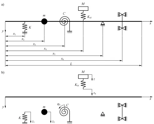
II. THE FORMULATION AND SOLUTION OF THE PROBLEM The considered system is shown schematically in Fig. 1. In Fig. 1a the system consisting of a uniform Bernoulli-Euler beam, translational and rotational springs, concentrated mass, linear undamped oscillator and additional supports against the beam translation or rotation is considered. The beam without the additional elements is the base system which must satisfy any arbitrary chosen boundary conditions, which can be obtained by the proper number and location of the considered support elements.
According to the procedure described in the paper [7] the kinetic and potential energies including all elements of the system before their connection, as shown in Fig. 1b, can be formulated. Thus, with respect to the Bernoulli-Euler beam theory the kinetic and potential energies can be expressed in the form:
Lb dx
t t x y x A t
T
0
2
) , ( ) ( 2 1 ) (
, (1)
L
b dx
x t x y x EI t
V
0
2
2 2
) , ( ) ( 2 1 ) (
, (2)
where y(x,t) is the lateral displacement of the beam at the point x, A(x) is the mass per unit length, I(x) is the mass moment of inertia per unit length and is the mass density.
On the basis of solution of the free vibration problem of beam with the specific supporting and without any attachments, the lateral displacement y(x,t) is expressed as follows
n i
i i x t
Y t x y
1
) ( ) ( )
,
( , (3)
where Yi(x) denotes the i-th transverse vibration mode and ξi(t) function of time.
Substituting expression (3) into equations (1) and (2), one obtains:
n i
i i
b t M
T
1 2
2 1 )
( , (4)
Algorithm for Automatic Analysis of Free
Vibrations of Uniform Bernoulli-Euler Beams
with Attachments
n i
i i
b t K
V
1 2
2 1 )
( , (5)
where:
L i
i A xY xdx M
0
2 ) ( ) (
, (6)
L i
i dx
x x Y x EI K
0
2
2 2
) ( )
( . (7)
Introduced coefficients Mi and Ki can be defined for the beam free at both ends. Using the solution of boundary value problem of such a beam, one can obtain the functions Yi(x) for this case as
x x
L L L
L x x
x Y
i i
i i
i i
i i
i
sinh sin
sin cos sinh
cosh cosh cos
) (
, (8)
where β4=ρAω2/(EI) and is the natural frequency of the considered beam.
Missing in formula (8) the values of i are calculated for the considered case from the equation
1
cosh
cos
L
L
. (9)The set of computed values of i one can find also in the cited paper [2].
Using the expression (8) and including (9) one can determine, based on (6) and (7), the values of coefficients Mi and Ki for the beam under consideration in the form [14]:
i
i
ALm
M
, (10)i
i
k
L
EI
K
3 , (11) [image:2.595.43.560.52.467.2]where the dimensionless quantities mi and ki have been introduced:
L L L L L L L
LL L
L L L L L L L m i i i i i i i i i i i i i i i i i i i i sinh sin 2 2 2 cosh 2 cos 4 2 sinh 2 sin sinh cos sin cosh sin cosh 4 2 sin sinh sinh cos 1 1 2 , (12)
L L L L L L LLL L
L L L L L L L L k i i i i i i i i i i i i i i i i i i i i i sinh sin 2 2 2 cosh 2 cos 4 2 sinh 2 sin sinh cos sin cosh sin cosh 4 2 sinh 2 sin sinh cos 2 3 4 , (13) where L L L L i i i i i sin cos sinh cosh
. (14)
Initially, the beam and the additional elements of the system are considered to be unconnected (see Fig. 1b). Based on (4) and (5) the total kinetic energy T of all components can be written as
2 2 2 1 2 2 1 2 1 2 1 z M z m M T n i i
i
(15)
and the total potential energy V in the form
2 4 2 3 2 1 1 2 ) ( 2 1 2 1 2 1 2 1 z z K C Kz K V M n i i
i
. (16)
The mathematical description of the combined system consisting of a beam and attached to it additional components that are connected to the beam in cross-sections with coordinates xk (k = 1, 2, ..., 6), as shown in Fig. 1a, must be completed by constraint equations that can be written in the following form:
0 ) ( 1 1 1y x z
f , (17a)
0 ) ( 2 2
2 y x z
f , (17b)
0 ) ( 3 3
3 y x
f , (17c)
0 ) ( 4 4 4 y x z
f , (17d)
0 ) ( 5
5 y x
f , (17e)
0 ) ( 6
6 yx
f . (17f)
The constraint functions fk (k = 1, 2, ..., 6) are also defined through these relationships.
The Lagrangian for the system may be written as
R r r rf V T L 1 , (18)
where r is the Lagrange multiplier and R is the number of the attachments in the system. In the considered case R = 6, according to the scheme in Fig. 1.
Using Lagrange’s equations for the system one obtains:
n i b K M R r ir r i i i
i 0, =1,2,...,
1
, (19a)
0
1 1
Kz , (19b)
0
2 2 z
m , (19c)
0
C33 , (19d)
0
4 4-z)λ (z
KM , (19e)
0 )
4
K (z z z
M M , (19f)
where: 3,6 dla ) ( 1,2,4,5 dla ) ( r= x
Y x r= Y b r i r i
ir , (20)
and the function Yi(xr) is defined by (8).
In order to solve the free vibration problem and determine the natural frequency ω the harmonic solution of equations (19) is assumed in the form:
, 1,2,..., =
, i n
e A j t
i
i
(21a)
1,2,4 = , k e Z z j t
k
k , (21b)
t j e
3 3 , (21c)
t j
z=Ze , (21d)
R r
ej t
r , =1,2,...
r
. (21e)
Substituting (21) into (19) the amplitudes Ai, Zk, 3, and Z can be determined as the functions of Lagrange’s multiplier amplitudes Λr. After appropriate transformations one obtains: i i R r ir r i M ω K b Λ
A 1 2
, (22a) 1 1 1 Λ KZ , (22b)
2 2 2 1 Λ mω
Z , (22c)
3 3
1
Λ
C
Φ , (22d)
4 2
4 1 1 Mω K Λ Z M , (22e) 4 2 1 Λ Mω
Substituting (22) into the constraint equations (17), one obtains the system of R equations which can be written in matrix form as
0
CΛ , (23)
where the vector = [Λ1, Λ2, Λ3, Λ4, Λ5, Λ6]T, and C is a square matrix of size equal to the number of attachments in the model. In the present case Chas the form
6 66 65 64
63 62
61
56 5 55 54 53
52 51
46 45
4 44 43 42
41
36 35
34 3 33 32 31
26 25
24 23
2 22 21
16 15
14 13
12 1 11
C C C
C C
C
C C
C C
C C
C C
C C C
C
C C
C C
C C
C C
C C
C C
C C
C C
C C
C ,
(24)
where the following coefficients have been introduced:
n
i i i
ir ik kr
M K
b b C
1
2
, (25a)
1 1
K
, (25b)
2 2
1
m
, (25c)
C
1
3
, (25d)
2 4
1 1
M KM
, (25e)
0 =
5
, (25f)
0 =
6
. (25g)
For non-trivial solution of the system of equations (23) the determinant of the matrix Cmust be zero, it means
0
detC , (26)
that is the equation for computation of the eigenfrequency ω of the combined system. In this equation the coefficients Ckr characterize the beam as the base system’s element and the coefficients εk characterize the additional elements attached to the beam. A number of attachments determines the size of the matrix. Therefore, for any system consisting of the beam connected with arbitrary number of attachments, it is possible to create the system of equations in the form (23), directly. The previously presented formulation and solution is valid for every such combined systems.
Therefore, in order to determine a new set of equations of the form (23), according to the number of additional
elements (attachments) connected with the beam to create the complex system, a square matrix of form (24) and the size equal to the number of attachments in the model can be determined. Each matrix element depends on the coefficient Ckr and the type of attachment characterized by the coefficient k. Thus, having defined the matrix C the natural frequencies of the considered continuous-discrete system can be determined from the equation of the form (26).
Additionally, after calculation of the frequency values of the complex system under consideration the mode shape corresponding to each determined frequency k can be computed. After suitable transformations, based on the derived formulas, the function Yk(x) describing the k-th mode shape of the complex system can be written as
ni
i i k i R
r
ir k r
k
Y
x
M
K
b
Λ
x
Y
1
2
1
(
)
)
(
. (27)
where Yi(x) denotes the i-th transverse vibration mode of the beam without the attachments in the form (8).
It should be noted that to determine, based on the formula (27), the mode shape of the beam as part of a complex system, it is necessary to solve the properly created set of equations, separately for each of the previously identified natural frequency k. Needed for this purpose sets of equations can be derived as the transformed system of equations obtained from the equations (23). To obtain the appropriate equations, one of the Lagrange multipliers should be chosen as a permanent independent and then the remaining (R - 1) amplitudes Λr(ωk) of Lagrange multipliers can be calculated based on equations (23) as the function of the one selected. In the formula (27) the amplitude Λr(ωk) represent amplitudes Λr determined from the modified set of equations corresponding to the frequency of k, which corresponds to the mode shape defined by (27). Therefore, the determining the frequency value k and the corresponding to them amplitudes of the Lagrange multipliers Λr(ωk) allows one to fully describe the free vibrations of the complex system on the basis of the described formulae.
For completeness, it is important to notice that the form of coefficients Ckr is obtained for the uniform Bernoulli-Euler beam free at both ends and without any attachments. To obtain the proper supporting of the beam in any considered combined system, apart from the attachments composing the system, the proper number and location of the additional discrete elements characterized by k (k=5,6) should be added. These elements enable one to define the proper supporting for any arbitrary chosen classic beam support.
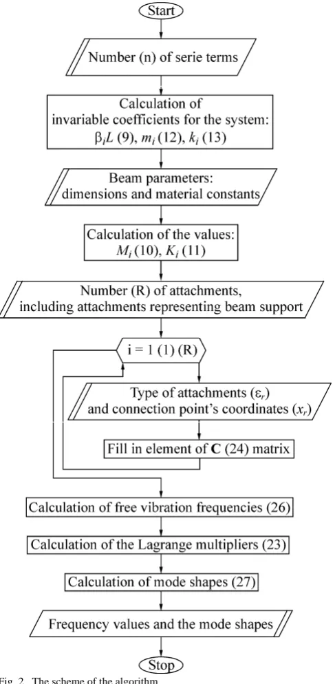
III. THE ALGORITHM FOR AUTOMATIC ANALYSIS OF FREE VIBRATIONS OF THE SYSTEM
On the basis of the mathematical model presented in chapter 2 the algorithm (Fig. 2) for automatic analysis of free vibrations of the complex systems has been created. In Fig. 2, beside the descriptions of calculated system parameters, the proper number (in parenthesis
)
of calculation formula is marked according to the numbering used in previous description of the model. The proposed algorithm enables one to analyze the free vibrations of any arbitrary chosen complex system consisting of elements taken to compose the considered in this work continuous-discrete system. Using the proposed algorithm the analysis of the free vibrations of complex system of considered type can be done automatically. After defining the systemparameters the formulation and solution of the free vibration problem is done numerically on the basis of build in mathematical model.
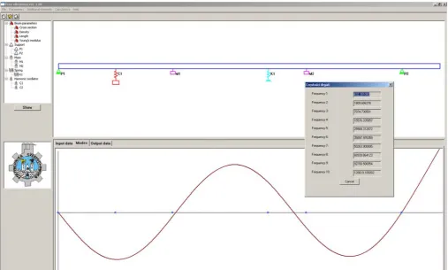
IV. THE SAMPLE RESULTS OF NUMERICAL CALCULATIONS On the basis of the presented mathematical model and the algorithm the program for numerical automatic analysis of free vibrations of the complex system has been worked out. The program enables one to determine the chosen number of eigenfrequency values and mode shapes for defined complex system according to the proposed algorithm. In Fig. 3 the sample results of numerical calculations obtained by using the program for the chosen configuration of the complex system have been presented.
The accuracy of the numerical results increases with the increase of the number n which defines the number of considered terms of series according to the formula (3). According to the increase of the number n the cost of numerical calculation also increases. So the proper value of this number should be chosen to get the lower cost and required accuracy. In practice, as it has been proved in [14] for similar calculations, even quit low number is suitable to obtain the results with satisfactory accuracy. It is important to remember that it is necessary to choose such number n that enables one to obtain the calculated eigenfrequency value for the complex system lower than the value for the last included in the calculation eigenfrequency of the beam without any attachments. These frequencies can be determined from the equation (9).
V. CONCLUSIONS
The algorithm and computational program for automatic analysis of free vibrations of complex systems have been worked out. The program enables one to analyze free vibrations of any arbitrary chosen complex system consisting of uniform Bernoulli-Euler beam with any number of attachments like: translational and rotational springs, concentrated mass, linear undamped oscillator and additional support elements. Using the proposed algorithm the analysis can be done automatically. After defining the system parameters the formulation and solution of the free vibration problem is done numerically on the basis of build in mathematical model. The formulation and solution of the problem has been based on the Lagrange multiplier formalism.
The important feature of the proposed model is that the mathematical model is created by using the analytical solutions. The numerical procedure for determining the frequency values allows one to determine the frequency values and corresponding mode shapes with required accuracy which can be improved by increasing the number of terms of the series considering during the calculation process. This number is a user defined parameter of the calculations.
[image:5.595.48.292.94.592.2]REFERENCES
[1] L. Ercoli and P.A.A. Laura, “Analytical and experimental investigation on continuous beams carrying elastically mounted masses”, Journal of Sound and Vibration, Vol. 114, 1987, pp. 519 - 533.
[2] C.N. Bapat and C. Bapat, “Natural frequencies of a beam with non-classical boundary conditions and concentrated masses”, Journal of Sound and Vibration, Vol. 112, 1987, pp. 177-182.
[3] C. Kameswara Rao, “Frequency analysis of clamped-clamped uniform beams with intermediate elastic support”, Journal of Sound and Vibration, Vol. 133, 1989, pp. 502 - 509.
[4] C. Kameswara RAO, “Frequency analysis of two-span uniform Bernoulli-Euler beams”, Journal of Sound and Vibration, Vol. 137, 1990, pp. 144 - 150.
[5] S. Q. Lin and C. N. Bapat, “Free and forced vibration of a beam supported at many locations”, Journal of Sound and Vibration, Vol. 142, 1990, pp. 343-354.
[6] S. Kukla, “The Green function method in frequency analysis of a beam with intermediate elastic supports”, Journal of Sound and Vibration, Vol. 149, 1991, pp. 154-159.
[7] B. Posiadala, “Use of Lagrange multiplier formalism to analyze free vibrations of combined dynamical systems”, Journal of Sound and Vibration, Vol. 176, 1994, pp. 563-572.
[8] S. Kukla, B. Posiadala, “Free Vibration of Beams with Elastically Mounted Masses”, Journal of Sound and Vibration, Vol. 175, 1994, pp.557-564.
[9] C. H. Chang, “Free vibration of a simply supported beam carrying a rigid mass at the middle”, Journal of Sound and Vibration, Vol. 237, 2000, pp. 733-744.
[10] J. J. Wu, “Alternative approach for free vibration of beams carrying a number of two-degree of freedom spring-mass systems”, Journal of Structural Engineering-ASCE, Vol.128, 2002, pp. 1604-1616. [11] M. Gürgöze, “On a determinant formula used for the derivation of
frequency equations of combined systems”, Journal of Sound and Vibration, Vol. 265, 2003, pp. 1111–1115.
[12] P. D. Cha, “A general approach to formulating the frequency equation for a beam carrying miscellaneous attachments”, Journal of Sound and Vibration, Vol. 286, 2005, pp. 921–939.
[13] B. Posiadala, Modeling and Analysis of Dynamical Phenomenon of Heavy Construction Machines and its Elements as Discrete-Continuous Mechanical Systems, Publishing House of Czestochowa University of Technology, series Monographs no 61, 1999 (in Polish). [14] B. Posiadala, Modelling and analysis of continuous-discrete
[image:6.595.49.557.53.358.2]mechanical systems. Application of the Lagrange multiplier formalism, Publishing House of Czestochowa University of Technology, series Monographs no 136, 2007 (in Polish).