Abstract—Impact of free flying projectiles onto flat plates produces characteristically different types of response whose boundaries and transitions have previously been identified based on macro scale variables such as projectile mass and velocity. This paper explored the limitations of the macro scale approach specifically focussing on the boundary transitions that contain the most complex behaviour, by observing time evolution profiles of normal, shear and Von-Mises stresses. It also showed details of behaviour that has not previously been observed through other methods.
Index Terms—Impact, stress profiles, regime transitions.
I. INTRODUCTION
MPACT events, can be viewed as a special case of dynamic loading conditions, primarily due to the singularity of an instantaneous step change from no contact to contact. If the singularity is accepted as the primary defining criteria to define impact as being separate from any other loading condition, then secondary level descriptions would include whether the distinct masses involved are two or more in number, solid or fluid, other material classifications, geometry, and initial conditions such as position and motion, state and boundary conditions. The subsequent time evolution of the behaviour of the system after the time of first contact also needs classification. A full and universally accepted hierarchical means of classifying impacts, firstly in terms of initial conditions before impact and then the subsequent impact behaviour, does not exist. This paper considers the case of a free flying projectile impacting onto a flat clamped plate, with the objective of working towards the development of the resolution of observed characteristic behaviour, and hence towards an improved classification of impact behaviour.
In broad terms, impact behaviour covers a wide spectrum from Quasi-Static (QS) to highly dynamic and transient, and studies have shown the existence of impact regimes within that spectrum [1]-[4]. Researchers tend to fragment the spectrum into regimes in search of ever more tightly defined
Manuscript received March 17th, 2011; revised April 5th, 2011.
P. W. Bland is with The Sirindhorn International Thai-German Graduate School of Engineering (TGGS), King Mongkut’s University of Technology North Bangkok (KMUTNB), 1518 Pracharaj 1 Rd, Wongsawang, Bangsue, Bangkok 10800, Thailand. (Tel: +66 2913 2500 ext 2915; Fax: +66 2913 2500 ext 2922; email: [email protected])
S. Tiranasawadi is with TGGS, KMUTNB, address as above. (email: [email protected])
P. W. Bland is grateful to Livermore Software Technology Corp. for the donation of LS-DYNA used in this work, and to TGGS for funding attendance of the conference.
criteria and characteristic events or behaviour, with the resolution required depending on the application, the available computational power or measurement resolution, or as a next step from a theoretical point of view towards a better understanding of the underlying impact mechanics. A first step is to split the spectrum into QS, low-dynamic and high-dynamic [1], as well as considerations of strain rates and wave propagation. With reference to the initial conditions of projectile mass and velocity, behavioural regime boundaries have been experimentally observed and classified into independent scales of Velocity (V) and Mass (M) [2]. Each scale has a Transition (T) regime, between two boundaries, that separates High (H) or Low (L) regimes, giving four extreme regimes of LV/LM, LV/HM, HV/LM and HV/HM. LV/LM is generally of such a low energy that it produces little observable response and of little engineering interest. LV/HM is typically a QS response, characterised by long contact duration, a structural response shape close to the static loading shape or first mode shape with the projectile attached to the target in the case of projectile rebound. Such target deformations are here referred to as global deflection. HV/LM is typically highly transient, short contact times, deflection localised to the contact area, at best involving higher order modes. HV/HM is generally of such high energy that total destruction results, and not considered. The mass transition was characterised by discontinuous contact, with the LM and HM regimes both having continuous contact. The velocity transition was characterised by observing a delay in the formation of a global deflection, with LV having near instantaneous formation of the global deflection and HV not observing any global deflection at all, and only local deflection, if any [3]. A regime classification criterion based solely on mass has been proposed [4] which shows reasonable qualitative agreement with some of the previously mentioned experimental observations, but does not recognise the role played by velocity. The arguments in favour of velocity not being a factor often have mirrored and equally flawed arguments as to mass not being a factor. Selected cases or parametric ranges can be chosen in support of this, but the broader picture, when sweeping fully across both mass and velocity ranges does highlight a role played by both.
However, the authors propose that none of these classification or criterion approaches can fully account for all cases of impact or even for any single case of impact in sufficient detail. On closer inspection, the definitions or even the existence of regime boundaries can be questioned, and hence so can the transitions between them. Fundamentally speaking, this assertion is based on three key
A Study of Impact Regime Boundary
Transitions
Paul W. Bland and Sarin Tiranasawadi
points. Firstly, the concept of resolution, demonstrated by asking questions such as what do we mean by high or low, and therefore how do we define or measure the location of any boundary? Secondly, are the different types of response really separated by boundaries that show a sudden change in behaviour, or is there a gradual and continuous mixing of response types? Thirdly, are the macro level parameters, such as mass or target thickness, sufficient to characterise the real complex impact behaviour?
Nevertheless, the previously described boundaries and transitions using velocity and mass are used in the current work as a frame of reference, to describe the initial conditions and subsequent impact behaviour. This is referred to here as a macro level approach.
It is proposed that in order to account for all cases of impact, a different approach is needed based at the fundamental stress wave level that also avoids a classification system when measuring or predicting the behaviour [2]. These waves are on the smallest time and dimensional scales possible, being longitudinal and transverse waves that are initiated at the time of first contact, and beyond. For simplicity, these are referred to here as micro stress waves.
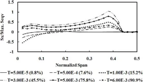
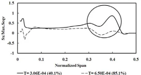
[image:2.595.52.287.423.559.2]A first step towards the small scale level, to try to gain some insight and bridging the gap between macro and micro scales, as presented in this paper, has been to look at the time step development of normal and Von-Mises stresses for impact conditions that are in the extremes of LV/HM and HV/LM, far removed from any boundary [5], as shown in Fig. 1 and Fig. 2.
Fig. 1 Characteristic Sx profiles for HV/LM extreme impact regimes.
Fig. 2 Characteristic Sx profiles for LV/HM extreme impact regimes.
The stresses are normalised against the maximum Von-Mises stress observed during impact, and are plotted against normalised span dimensions with the centre span and contact location being at zero, and the plate edge at 0.5. The clamped area is easily visually identified in Fig. 1 and Fig. 2 by the section of the plate with zero stress for all time. Time (T) is shown with absolute figures in units of seconds and normalised against the total contact time and shown as a percentage in brackets. The resulting stress profiles show markedly different characteristics for the two extreme impact regimes. A key difference is that HV/LM shows a profile shape that changes throughout the contact duration with three identifiable phases, whereas LV/HM shows a profile shape that is approximately constant, but only changing in amplitude (except for the section of the span where the amplitude switches between positive and negative values due to the tension/compression sign convention). On closer inspection, it is observed that the impact cases with initial conditions defined as LV/HM actually do include a very short lived stress profile behaviour which is associated with the HV/LM regime, for a maximum of 2-7% of the total contact time at the start of contact for the tested cases. This confirmed the limitation of using the macro level approach to defining impact conditions and behaviour.
When the stress profile shapes change over time, as characterised by HV/LM response, they can show wave like behaviour, but these waves are not the micro stress waves, and are therefore referred to here as macro stress waves. This is an important distinction to make. The goal of the current work is to eventually look at the micro stress wave level, but first, as in this paper, the macro stress waves must be studied.
Studies have used a micro stress wave approach, but, within any given single study, tend to do so for a relatively narrow range of impact conditions and therefore not making detailed comparisons between different impact response types [6]-[8]. Other studies have looked at the macro stress wave level, but again without comparing different response types or by only looking at stress evolution at a limited number of fixed spatial points in the target and not observing profiles across the whole span or explicitly on a time step evolution basis, or solely for the purpose of material orientated investigation [9], [10]. The authors have not found literature that focussed on the study of macro or micro level stress waves explicitly for the purpose of developing a better fundamental understanding of the governing impact mechanics including transitions between identified behavioural regimes.
II. METHODOLOGY
The work reported here focussed on observing macro stress wave behaviour, associated with the impact regime transitions defined above, in linear independent scales of mass and velocity. The aim was to identify characteristic time evolution full span stress profile development, and observe key features that could be associated with the macro level observations of the regime transitions.
[image:2.595.52.285.603.736.2]rigidly clamped across their two short sides. The development of the macro stresses (normal stresses in three directions, shear stresses in one plane and Von-Mises stress) along the span on the impacted surface at mid-plane was observed.
The steel projectile, aluminium and titanium plates were meshed with an eight node solid element defining the x axis along the span, y axis through the thickness, and z axis across the plate width, with the origin at the centre of the plate on the top impacted surface. For all cases, finer meshes were used for the area near the contact point and gradually coarser meshes for the remaining region.
Projectile material was steel (high alloy steel AMS-6521) with density of 7850 kg/m3, Young’s Modulus of 200 GPa, and Poisson’s ratio of 0.3, assigned as a rigid body within LS-DYNA. The aluminium (5086-H36) and titanium (Ti-6Al-2Sn-4Zr-2Mo) plates were assigned as elastic-plastic strain hardening materials within LS-DYNA with densities of 2770 and 4620 kg/m3, Young’s moduli of 71 and 96 GPa, Poisson’s ratios of 0.33 and 0.36, yield strengths of 280 and 930 MPa, and tangent moduli of 500 and 2150 MPa
respectively [11]. Values for projectile mass, impact velocity, target span and thickness are given in Table I.
The focus of the work was not to develop damage mechanics modelling, but it was deemed necessary to rerun the simulation of the Aluminium plate for 2 mm and 4 mm
thick plates with a basic level of a damage model so as to be able to check the difference in the results with and without the damage model. This produced 8 more cases, mapping case numbers 1 and 2 to cases 25 and 26, case numbers 4 and 5 to cases 27 and 28, case numbers 7 and 8 to cases 29 and 30, case numbers 10 and 11 to cases 31 and 32. The model used an element erosion approach, selecting the LS-DYNA “eroding nodes to surface”contact algorithm for the contact condition between the projectile and target. An element was removed once the effective plastic strain in the element reached the critical value of 0.2 [12].
All results from simulation cases were normalised. All stresses (Sx, Sy, Sz, Sxy) were normalised with the maximum value of Von-Mises Stress (Seqv). Time (T) was normalised with total contact time. The x direction was normalised with the span, and y direction normalized with plate thickness.
III. RESULTS
A. Characterisation using the mass and velocity regime definitions
As previously explained, the macro level method of characterising the regimes, although flawed, still has its uses, and is used here in Table I. Table I classifies the impact response for each case, with reference to the mass and velocity regimes. The regimes are split into seven sub ranges of extreme low (EL), low but just below the boundary between low and transition (LB), in the transition but just above the low boundary (TLB), in the middle of the transition (T), in the transition but just below the high boundary (THB), high but just above the boundary between high and transition (HB), and extreme high (EH).
Most cases are confirmed to be within the transition regimes (TLB, T, and THB codes for both mass and
velocity scales). The cases that are not in the transition regimes, but in the extremes (EL, LB, HB, and EB codes for both mass and velocity scales) are as follows: Cases 1-3, 7-9, 10-11, 13, and 20-22 for the mass scale, and cases 3, 6, 17, and 18 for the velocity scale.
For a given mass and velocity, the impact response classification changes dependant also on the target material, span and thickness. This confirms one of the main flaws of the macro approach, in that regimes defined solely by mass and velocity cannot give absolute values of boundary locations, except when all other variables are held constant. As an example, cases 7-9 gave a response classified as being in the extreme high mass regime, but upon increasing the span, cases 10-12 show a response close to the high mass boundary, with cases 10 and 11 outside the transition but just above the high mass boundary and case 12 within the transition just below the high mass boundary. The sensitivity of the velocity regime classification to varying target parameters was less than that of the mass boundary. Changing from aluminium to titanium, increasing span and thickness tended to move the response from the extremes in towards the transition regimes.
TABLE I
SIMULATION CASE SPECIFICATION AND RESPONSE REGIMES
B. Characterisation using stress profiles
Fig. 3 Typical Sx profile for the transition regime, showing profile development before switching, matching the characteristic HV/LM type profile (case 4).
Fig. 4 Typical Sx profile for the transition regime, showing profile development after switching, matching the characteristic LV/HM type profile (case 4).
Fig. 5 Sx profile for a case without a delay in the formation of global deflection (case 6).
Fig. 6 Sx profile for a case with a delay in the formation of global deflection (case 10).
For all transition regime cases, and after the switching time, the Sx profiles are smooth if there is no observed delay in setting up a global deflection. If there is a delay, then the profiles show a superimposed ripple. This effect is more
pronounced the closer the impact condition is towards the middle of the transition, and reduces as the impact condition moves towards a boundary. Observations of continuous or discontinuous contact did not correlate to whether ripple occurs or not. The ripple effect was also seen for Sz and Von-Mises stress profiles, but the ripple amplitude was lower. The effect was difficult to observe using Sxy as there was always a ripple feature, even without any delay. An example can be seen in Fig. 5 and Fig. 6, showing only two time steps for clarity.
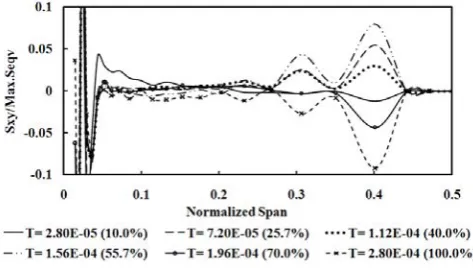
The Sxy profiles also showed the same general switching behaviour in terms of a characteristic HV/LM profile (its shape changing and expanding across the plate span with time) switching over to a LV/HM profile (a constant shape across the full span but only changing in amplitude), with the switch also occurring between 9.8 % and 15.1 % contact time. As for Sz profiles, for cases with discontinuous contact, the loss of contact occurred after the switching time. The profile’s normalized amplitudes were very low, and the characteristic HV/LM profiles contained no clear useful detail for this reason. Typical LV/HM profiles are shown in Figs. 7-9, which also shows how the characteristic profiles evolve as a function of plate thickness.
Key features are the maximum values near the contact and clamp areas being less than 0.2 % of the Von-Mises maximum values, and the formation of the distinct peaks as for the 8 mm thick plates. These two peaks cross the span axis with zero amplitude at approximately constant span wise distances. The larger peak is partly under the clamped surface, with its maximum coinciding with the clamp edge in the span wise direction. For thinner plates, these two peaks become less dominant. For all thicknesses and for continuous contact, the peaks’ amplitudes increase and then decrease during the LV/HM characteristic phase. For cases with a loss of contact for a significant percentage of the contact time, there is a strong oscillatory behaviour whereby the peaks’ amplitudes increase, decrease, increase and decrease again. This sometimes included a reversal of the sign of amplitude. In an extreme case of loss of contact, and very distinct peaks for the 8 mm thick plate, the oscillation dominates and reverses sign several times, as shown in Fig. 9. In changing the initial impact condition to favour a tendency to lose contact, the oscillation behaviour becomes stronger.
The Sy profiles were of limited use, in all cases looking like the examples shown in Fig. 10 and Fig. 11. The stress in the y direction under the contact area peaked at a normalized value of 1.0, as expected, due to the dominating projectile contact force. The peak shown in Fig. 10 and Fig. 11 at approximately 0.4 normalised span again overlaps the clamped surface, and is also to be expected as a consequence of the clamping force increasing as a response to projectile contact. It was not easy to observe specific switching times, between the early contact time characteristic HV/LM behaviour and the later LV/HM behaviour, due to the low amplitudes.
The Sz profiles also showed the same general switching behaviour occurring between 9.8 % and 15.1 % contact time, and for cases with discontinuous contact, the loss of contact occurred after the switching time. For all cases, the
Sz profiles showed all other similar behaviour as for Sx
[image:4.595.53.284.403.521.2] [image:4.595.52.284.562.685.2]Fig. 7 Sxy profiles for 2 mm thick plate (case 4).
Fig. 8 Sxy profiles for 4 mm thick plate (case 5).
Fig. 9 Sxy profiles for 8 mm thick plate (case 6).
For increasing thickness, Sx, Sz, and Von-Mises stress profiles showed characteristic profiles of HV/LM and LV/HM more clearly. For increasing thickness, Sxy stress reduced over the whole plate span except near the contact and clamped areas as shown in Fig. 7-9. Observing the stress profiles also confirmed the general observation that changing from aluminium to titanium, increasing span and thickness tended to move the response from the extremes in towards the transition regimes.
C. Comparison of key results with and without the damage model
Cases 25 – 32 included the damage mechanics model. Case 26 showed no damage defined by no deleted elements, as a result of low impact energy and high stiffness giving low strains and hence low strain rates. Case 26 matched case 2 in all aspects, as described in section B, both qualitatively and quantitatively. Cases 25, 27, and 28 resulted in damage but no perforation, again consistent with having low impact energy. Cases 25, 27, and 28 matched cases 1, 4, and 5 in all
aspects qualitatively, with only small differences quantitatively. Cases 29 to 32 resulted in damage and perforation. Cases 29 to 32 showed different results to cases 7, 8, 10, and 11 both qualitatively and quantitatively. However, all such differences only ever occur at the qualitative level after the time of perforation, meaning all the key observations described in section B up to this point in time are valid. All such differences only ever occur at the quantitative level for times after elements are deleted.
Fig. 10 Sy profiles (case 4).
Fig. 11 Sy profiles (case 5).
REFERENCES
[1] S. Hiermaier, M. Boljien, I. Rohr, “High Speed Impact – Test and simulation”, in Proc. 7th European LS-DYNA Conf, Salzburg, Austria, 14th-15th May, 2009, A-II-04.
[2] P. W. Bland, “Impact response and performance of carbon-fibre reinforced polymers”, Ph.D. Thesis, Dept. Mech. Eng, Imperial College, London, 2000.
[3] P. W. Bland and N. Chollacoop, “Experimental observations of mass and velocity parametric sweeps of impact regime boundaries”, in
Proc. 20th Conf. Mech. Eng. Network Thailand, Nakhon Ratchasima,
Thailand, 18th-20th October, 2006, AMM046.
[4] R. Olsson, “Mass criterion for wave controlled impact response of composite plates", Composites: Part A, vol. 31, pp. 879–887, 2000. [5] P. W. Bland and S. Tiranasawadi, “A study on impact mechanics
regimes by using stress waves”, in Proc. 15th Int. Annual Symposium
on Computational Science and Eng., Bangkok, Thailand 30th
March-1st April 2011, accepted for publication.
[6] M. S. H. Fatt and D. Sirivolu, “A wave propagation model for the high velocity impact response of a composite sandwich panel”, Int. J.
Of Impact Eng., vol. 37, pp. 117-130, 2010.
[7] C. Wu, L. Li and C. Thornton, “Energy dissipation during normal impact of elastic and elastic-plastic spheres”, Int. J. Of Impact Eng., vol. 32, pp. 593-604, 2005.
[8] D. Karagiozova, “Dynamic buckling of elastic-plastic square tubes under axial impact-I: Stress wave propagation phenomenon”, Int. J.
[image:5.595.49.286.217.349.2] [image:5.595.49.286.378.513.2][9] M. Stoffel, “Shape forming of shock wave loaded viscoplastic plates”, Mechanics Research Communications, vol. 33, pp. 35-41, 2006.
[10] O. L. Valerio-Flores, L. E. Murr, V. S. Hernandez, and S. A. Quinones, “Observations and simulations of the low velocity-to-hypervelocity impact crater transition for a range of penetrator densities into thick aluminium targets”, J. Of Material Science, vol. 39, pp. 6271-6289, 2004.
[11] Military handbook: Metallic materials and elements for aerospace
vehicle structures, Department of Defence, U.S.A., MIL-HDBK-5J,
31st January 2003, http://www.everyspec.com
[12] B. J. MacDonald, “A computational and experimental analysis of high energy impact to sheet metal aircraft structures”, J. Of Materials