A Modified DTC Controller for DFIG-Based Wind
Energy System
T. Muni Prakash1, S. Ramakrishnan2
1
Sr. Asst. Prof. EEE Dept. New Horizon College of Engg., Banglore
2
Asst. Prof. EEE Dept. New Horizon College of Engg., Banglore
Abstract: This paper presents an modified direct torque control (DTC) method for the wind power system based on the doubly-fed induction generator (DFIG). The basic principle of direct torque control based on DFIG Asystem is analyzed. A modified strategy is presented by increasing the division accuracy of rotor flux position and the number of basic voltage vectors. The proposed method improves the performances of the system and reduces the rotor and torque ripples. By comparing the simulation results of the conventional and the improved DTC method applied in DFIG-based wind power system, the effectiveness of the proposed control method is validated.
Keywords: DFIG, Conventional DTC, Modified DTC, space voltage vectors & wind power generation.
I. INTRODUCTION
Due to the power electronic improvement and its high reliability, doubly-fed induction generators (DFIG) have clear superiority in the applications of wind power generation [1]. The main advantage of the DFIG is that the power converter transmits only a fraction of the total power (20-30%) which means the losses are relatively low [2].
The direct torque control (DTC) method has been widely applied in DFIG because of its good performance, simple structure and low parameter dependency [3]. In the DTC system, a proper voltage vector is selected from a switching table, which is determined by the torque hysteresis, the flux hysteresis and the position of rotor flux [4]. It minimizes the use of machine parameters and reduces the complexity of vector control algorithm [5].
The DTC method is an alternative to vector control for DFIG based wind power generation. High torque ripple are the main limitations of hysteresis based DTC [6], [7].
The conventional DTC method has some notable drawbacks, including irregular flux and torque ripples at steady state. Paper [8] has used a strategy of subdividing the space voltage vectors to solve the problem.
In this paper, an modified DTC strategy for DFIG applied in the wind power generation is proposed by increasing both the division accuracy of the rotor flux position and the number of basic voltage vectors. Consequently, a new switching table is designed according to the new logic judgment. The flux trajectory is approximately circle, and the flux and torque ripples are greatly reduced in the improved DTC method. The simulation results prove that the DFIG system has better steady-state performances and faster response of rotor speed for the change in wind velocity by using the improved DTC method.
II. MODELING OF DFIG
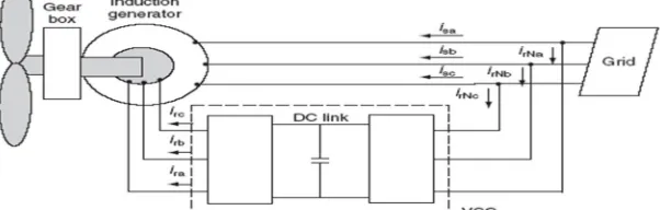
As shown in Fig. 1, in the DFIG based wind power generation system, the stator windings of DFIG are directly connected to the grid and the rotor windings are fed through back-to-back variable frequency converters [9]. The main focus of this paper is on the rotor-side converter, in which the DTC strategy is appliedLr is the rotor inductance, Lm is the mutual inductance between the rotor
[image:1.612.156.457.622.718.2]and stator. Ψs is the stator flux, Ψr is the rotor flux and θ is the phase angle difference between them.
band comparators.
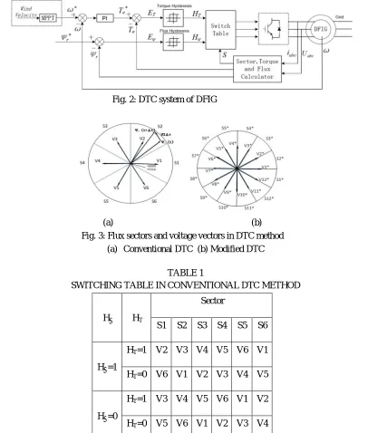
Fig. 2: DTC system of DFIG
(a) (b) Fig. 3: Flux sectors and voltage vectors in DTC method
[image:2.612.105.511.227.705.2](a) Conventional DTC (b) Modified DTC
TABLE 1
SWITCHING TABLE IN CONVENTIONAL DTC METHOD
Hψ HT
Sector
S1 S2 S3 S4 S5 S6
Hψ=1
HT=1 V2 V3 V4 V5 V6 V1
HT=0 V6 V1 V2 V3 V4 V5
Hψ=0
HT=1 V3 V4 V5 V6 V1 V2
HT=0 V5 V6 V1 V2 V3 V4
(a) (b)
Fig. 4: Flux trajectory (a) Conventional DTC (b) Modified DTC
In the conventional DTC method as shown in Fig. 3(a), there are 6 rotor flux position sectors, S1-S6, and each sector occupies 60 degrees. There are totally 8 switching combination, 6 of which are active vectors V1-V6 and the other two are zero vectors V0, V7. For instance, when the rotor flux Ψr (t) lies in sector S2 and the voltage vector V3 is applied for a period of time Δt,Ψr (t) will go to Ψr (t+Δt).
In the traditional DTC controller, the voltage vector selecting rules by means of basic DTC are presented in table 1, which is designed on the basis of the hysteresis comparators and the rotor flux sector. As shown in Fig. 4(a), the flux vector reference and the hysteresis band both track an approximately circular path. Thus, the rotor flux follows its reference within the hysteresis band in a zigzag trajectory.
It can be seen that the flux trajectory in conventional DTC has relatively large ripples determined by the hysteresis band width, which causes some drawbacks of the system, including large flux and torque ripples at steady state. In order to improve the operating performance by using DTC in DFIG, this paper proposes an improved strategy by increasing both the division accuracy of rotor flux position and the number of basic voltage vectors as shown in Fig. 3(b). In this method, there are 6 more basic space vectors that are added in the direction of angular bisector between each 2 adjacent vectors in Fig. 3(a). Similarly, 6 new sectors are composed. According to the improved strategy, the new space vector selecting rules are presented in table 2.
As shown in Fig. 4(b), within the hysteresis band of the same width as Fig. 4(a), the new system using the improved DTC method has smaller ripples in the rotor flux’s circular path due to a higher division accuracy of both position sectors and basic voltage vectors
Table 2 Switching Table In Modified Dtc Method
Hψ HT
Sector
S1* S2* S3* S4* S5* S6* S7* S8* S9* S10* S11* S12*
Hψ=1
HT=1 V3* V4* V5* V6* V7* V8* V9* V10* V11* V12* V1* V2*
HT=0 V10* V11* V12* V1* V2* V3* V4* V5* V6* V7* V8* V9*
Hψ=0
HT=1 V4* V5* V6* V7* V8* V9* V10* V11* V12* V1* V2* V3*
HT=0 V9* V10* V11* V12* V1* V2* V3* V4* V5* V6* V7* V8*
[image:3.612.98.514.515.728.2](b)
Fig. 5: Response of rotor speed as wind velocity changes (a) Conventional DTC (b) Modified DTC
The dynamic performances of DFIG-based system are shown in Fig. 5(a), and Fig. 5(b). As the wind velocity changes, the rotor speed follows the reference determined by MPPT strategy to capture the maximum of the wind power. The rotor speed in the improved DTC system has a faster response compared with the conventional system. The steadystate performances of the system are shown below.
(a)
(b)
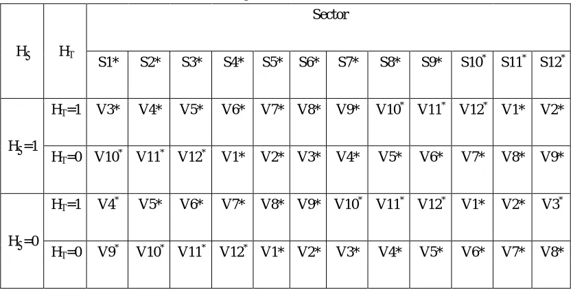
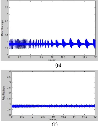
Fig. 6 Magnitude of rotor flux: (a) Conventional DTC (b) Modified DTC
(a)
[image:4.612.212.399.466.706.2](a)
[image:5.612.213.402.75.387.2]
(b)
Fig. 7 Magnitude of electromagnetic torque: (a) Conventional DTC (b) Modified DTC
Fig. 6(a), Fig. 6(b) show that the rotor flux ripple of the DFIG system using the improved method is smaller than that of the system using the conventional method. Both the two figures show the average amplitude of the rotor flux is 0.814 pu. While the maximum deviation of the rotor flux in Fig. 6(a) is 0.435 pu and the maximum deviation of the rotor flux in Fig. 6(b) is 0.155 pu. That means the DFIG system using the new DTC method has reduced the deviation of the rotor flux by 64.4%.
Fig. 7 (a) and Fig. 7(b) show that the electromagnetic torque ripple of the DFIG system using the new method is smaller than that of the system using the conventional method. It can be seen that the average amplitude of the electromagnetic torque is 0.4. While the maximum deviation of the electromagnetic torque in Fig. 7(a) is 0.211 pu and the maximum deviation of the electromagnetic torque in Fig. 7(b) is 0.042 pu. It can be concluded that the DFIG system using the new DTC method has reduced the deviation of the electromagnetic torque by 80.1%.
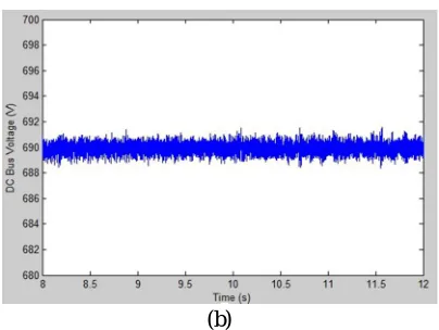
(b)
Fig. 8 The DC-link voltage (a) Conventional DTC (b) Modified DTC
V. CONCLUSION
In this paper, an modified DTC method for DFIG-based wind system, which increases both the division accuracy of rotor flux position and the number of basic voltage vectors, is introduced. The simulation results are presented and show the effectiveness of the proposed DTC method that helps to reduce the rotor flux, torque ripples and the DC-link voltage ripple. The results prove that the system has better dynamic performances by using the improved method as well.
REFERENCES
[1] A. Bakouri, A. Abbou, H. Mahmoudi, and K. Elyaalaoui, “Direct torque control of a doubly fed induction generator of wind turbine for maximum power extraction,” in IEEE Renewable and Sustainable Energy Conference, 2014, pp. 334-339.
[2] S.Belfedhal and E. Berkouk, “Modeling and Control of Wind Power Conversion System with a Flywheel Energy Storage System", International Journal Of Renewable Energy Research,2011, vol.1, pp.4352,
[3] Y. Zhang, Z. Li, T. Wang, W. Xu, and J. Zhu, “Evaluation of a class of improved DTC method applied in DFIG for wind energy applications,” in IEEE Electrical Machines and Systems International Conference, 2011, pp. 1-6.
[4] I. Takahashi and T. Noguchi, "A New Quick-Response and High Efficiency Control Strategy of an Induction Motor," IEEE Trans. Ind. Appl., vol. IA-22, pp. 820-827, 1986.
[5] J. Hu and X. Yuan," VSC-based direct torque and reactive power control of doubly fed induction generator", Renewable Energy vol. 40, pp 13-23, 2012
[6] D. Zhi and L. Xu, “Direct Power Control of DFIG With Constant Switching Frequency and Improved Transient Performance,” in IEEE Trans. Energy Conversion, vol. 22, pp. 110-118, March 2007.
[7] Y. Lai and J. Chen, “A New Approach to Direct Torque Control of Induction Motor Drives for Constant Inverter Switching Frequency and Torque Ripple Reduction,” in IEEE Trans. Energy Conversion, vol. 16, pp. 220-227, Sept. 2001.
[8] G. Liu, Y. Zhang, Z. Chen, and H. Jia, “PMSM DTC predictive control system using SVPWM based on the subdivision of space voltage vectors”. in Power Electronics and Motion Control Conference, 2009, pp. 1818-1821
[9] N. Zarean, and H. Kazemi, “A new DTC control method of doubly fed induction generator for wind turbine,” in IEEE Renewable Energy and Distributed Generation Conference, 2012, pp. 69-74.
[10] Z. Liu, OA. Mohammed, and S. Liu, “A novel direct torque control of doubly-fed induction generator used for variable speed wind power generation,” in IEEE Power Engineering Society General Meeting, 2007, pp. 1-6.