Design & Fabrication of Air Cooler using Peltier
Modules
Rai Ankit1, Shaikh Mohd. Hussain2, Gupta Ravichandra3
1, 2, 3
Department of Mechanical Engineering, Pillai College of Engineering, New Panvel, Maharashtra, India
Abstract: The project aims to design & fabricate a cooling system using Peltier modules. Peltier modules are thermoelectric devices capable of producing cooling & heating effect with help of electrical power, thus capable to cool or heat surrounding air. This project focuses on designing a duct which would draw fresh outdoor air & cool the air with the help of Peltier modules. This air would then be given to the blades of ceiling fan which would further circulate it within the room & provide cool air to the occupants under the fan. The Peltier modules mounted inside a ducting system, which would cool the air flowing through the duct. The surface area is increased by providing fins on the cooling side & the hot junction is cooled by recirculation of coolant. The heat exchanger in the circuit helps to lower the temperature of the coolant. The duct contains blowers to help flow of air through the ducts. The system also provides ventilation by constantly drawing fresh air from the outdoor environment. The inlet of the duct has a desiccant dehumidifier which absorbs the moisture content from the inlet air thus dehumidifying the air. The exhaust duct has a heating coil which helps in regeneration of the desiccant dehumidifier by carrying away the moisture into the outdoor environment. The enthalpy wheel is kept in constant rotation at a low rpm with a help of a 12V dc motor. Air filter provided at the inlet of the duct to refrains dirt & dust particles from entering the system. Two DC fans provided in the exhaust duct to carry heat from the hot side of the module to outdoor environment.
Keywords: Peltier modules, thermoelectric, ventilation, desiccant.
I. INTRODUCTION
A. Need & Background
Mostly due to the high costs & high-power consumption it is difficult for majority of population in India to afford air conditioners. This brings out the need to develop low cost alternatives which use lesser power making it an affordable alternative to use. [2] The first important discovery relating to thermoelectricity occurred in 1821 when a German scientist, Thomas Seebeck, found that an electric current would flow continuously in a closed circuit made up of two dissimilar metals provided that the junctions of the metals were maintained at two different temperatures. In 1834, a French watchmaker and part time physicist, Jean Peltier, while investigating the “Seebeck Effect,” found that there was an opposite phenomenon whereby thermal energy could be absorbed at one dissimilar metal junction and discharged at the other junction when an electric current flowed within the closed circuit. [9]
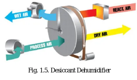
A compressor-based dehumidifier dehumidifies air by cooling the evaporator coils & as the humid air passed over the evaporator coil the moisture condenses & the air gets dehumidified. Compressor-based systems require high power & are costly. Whereas a desiccant dehumidifier uses a chemical called as desiccant which absorbs moisture from the air but regeneration is essential to avoid saturation of desiccant hence making use of a heating coil is imperative to use such dehumidifiers for commercial purposes.
[image:1.612.208.405.584.685.2]B. Peltier Effect
Fig. 1.1. Peltier Effect[10]
When a DC voltage is applied to terminals Tl & T2 an electrical current (I) will flow in the circuit. As a result of the current flow, cooling effect (Qc) will occur at thermocouple junction A where heat is absorbed & a heating effect (Qh) will occur at junction B where heat is expelled. [10]
[image:2.612.218.401.137.253.2]1) Working Principle of Peltier Device
Fig. 1.2. Working principle of peltier device[13]
Thermoelectric module or Peltier module, is a semiconductor based solid-state active heat pump which transfers heat from the cold side to its hot side. By application of a DC power source, the heat is moved through the module from cold side to hot side. The reversal of this phenomenon can also be done by a simple change to the applied DC polarity.
Two semiconductors of different material, one n-type & one p-type, are used because they need to have different electron densities. The semiconductors are placed thermally in parallel to each other & electrically in series & joined to a thermally conducting plate on each side. When a DC voltage is applied at the ends of the two semiconductors there is a flow of DC current across the junctions of the semiconductors causing a temperature difference. The cooling side absorbs heat & pumps to the hot side of the device. [10] 2) Thermoelectric Materials: There are several semiconductor materials such as Bismuth Telluride (Bi2Te3), Lead Telluride
(PbTe), Silicon Germanium (SiGe), & Bismuth-Antimony (Bi-Sb) alloys that may be used for making Peltier devices. But the most common material used for Peltier devices is an alloy of bismuth telluride that has been suitably doped to provide individual elements having distinct “N” & “P” characteristics. The selection of material is based on the figure of merit or relative performance for various materials over a range of temperatures. This can be illustrated from the graph shown. As the working range for the system is below 2000 C, Bismuth Telluride (Bi2Te3) would be the most suitable material. [11]
Fig. 1.4. Merit (Z) for several TE materials [11]
[image:2.612.187.431.465.593.2]Fig. 1.5. Desiccant Dehumidifier
II. DESIGN OF AIR COOLER COMPONENTS
A. Need & Background
The design of the system is created based on the objectives decided based on the need of the project. The CAD model is created & simulated for various parameters such as air flow, temperatures at various points of the system. Based on the data obtained the models are optimized until satisfactory results are obtained.
B. Design Of Duct
1) The design is based on Velocity reduction method. 2) Pv = (
∗ . ) mm of water [7]
3) Where V: velocity of flow
4) Pressure loss due to friction (Pf) is given by [7]
5) Pf = ∗ ∗
. ∗
6) Where t = temperature of air
7) m = c/s area of duct / wetted perimeter 8) m = (ab)/ (2 × (a+b))
9) f = friction factor
C. Calculations for Duct Considering rectangular section 1) Depth = d
2) Width (b) = 2d 3) Area (A) = b × d = 2 d2
4) Wetted perimeter = P = 2 (b+d) = 6d 5) m = A/P = 2d2/6d = d/3
6) Considering velocity (V) = 3.5 m/s (recommended velocity of velocity for residential air intakes)
7) Pv = (
. ) = ( .
. ) = 0.7505 8) Pf = ∗ * Pv
Considering air at 300C
9) Dynamic Viscosity = µ = 18.65 * 10-6 N-s/m2 10) Density of air = ρ = 1.16 kg/m3
11) Kinematic viscosity = µ/ρ = 1.60x10⁻⁵
12) Therefore Pf = ( . × . × × . ) = ( . )… eq (1)
13) Pressure drop per m length of duct = 0.2 mm of water 14) Length of duct = 1.5 m
15) Therefore Pf = 0.2 × 1.5 ………...eq (2) 16) Equating eq 1 & 2
17) 0.0185 = 0.2 × 1.5 18) d = 62 mm
19) b = 2 × d = 124 mm
20) Therefore, minimum size of duct required = 62 × 124 mm2 After simulating for the above dimensions, the cfm obtained was 56.99.
Also, the velocity of air flow passing over Peltier modules was high to get the desired cooling effect.
Hence, it is required to increase the cfm & reduce the velocity of flow therefore selecting a new blower of 200 cfm & increasing the duct dimensions to 120 × 240 mm2.
D. Calculation for Number of Peltier Modules
1) N = ( ) =
2) The heat load of air flowing through duct is calculated using [5] 3) Qf = C × mf × (hin – hout)
4) The value of hin & hout are calculated using psychrometric chart at 70 % relative humidity 5) hin = 78.618 kJ/Kg
6) hout = 56.289 kJ/Kg
7) for calculating mass flow rate (mf) 8) mf = density of air × discharge 9) mf = 1.25 × 0.047 = 0.06
10) Qf = 103 × 0.06 × (78.618 -56.289) = 1.33 KW Heat absorbed by one Peltier module (Qc) [5] 11) Qc = α ITc + 0.5 × I2 × r + K (Th - Tc) 12) α ITc = 185x10-6 × 6 × 278 = 308.58 W 13) 0.5 × I2 × r = 0.5 × 62 × 2.16 = 37.88 W 14) K (Th - Tc) = 1.28 × 55 = 70.4 W 15) Qc = 308.58 + 37.88 + 70.4 = 187.2 W 16) N = 1.33 / 0.187 = 7.11 ≈ 8 modules
E. Design of Perforated Block
1) The heat generated by the hot side of the Peltier modules has to be dissipated 2) The heat transfer is Watts is given by [6]
Q = ℎ[Tw−( )]
3) For finding the value of convective heat transfer coefficient (h):
discharge rate = A × V = 0.028 × 10⁻³ m3/s 0.028x10-3 = 5.02x10⁻⁵ × V 4) Therefore, V = 0.5636 m/s
5) Now, Reynolds no. Re = ( ) = (1.087 × 1000 × 0.5636 × 8 × 10-3) / (10.0052)
7) Hence the flow is laminar flow. 8) Thus, the Nusselt no. is given by
Nu= 0.646 × Re1/2 × Pr1/3 9) where Pr = Pr&tl number & Pr is given by
Pr= ( )= ( . .
. ) = 48.943 10) Therefore Nu= 0.646 × (942.51)1/2 × (48.943)1/3 = 72.544
11) Nu = ( )= ( . .
. )
12) Therefore, h = 2339.566 W/m2 K 13) Now,
14) Q = ℎ [Tw−( )]
15) A = Q / ℎ [Tw−( )]
16) A = 0.02954 m2
Therefore, the minimum required for heat transfer is 0.02954 m2, but taking design considerations, availability & easy of manufacturing increasing the area of heat transfer to 0.07559 m2.
F. Design of Radiator
The coolant coming out of the cooling coil is of considerable high temperature which must be cooled down to some temperature so that it can be re circulated into the circuit again for cooling. This coolant is cooled using a radiator.
Design of radiator
For calculation purpose, assuming that heat lose by the coolant = heat gained by air Therefore,
1) ṁc × cpc × (Tco - Tci) = ṁa × cpa × (Tai – Tao)
2) 0.0857 × 1006 × (Tco - 25) = 0.02 × 4.2 × 103 × (70 - 35) 3) Tco = 59.08 0C …….outlet temperature of coolant 4) Now, Heat capacity ratio (R) is given by [8]
R =
R = ( . × . × )
( . × ) = 0.810 5) The effectiveness of heat exchanger is given by [8]
E = = (( – – ) ) = 0.7
6) Now, the number of transfer units can be calculated as follows [8]
NTU = ln [1 + R ln (1 - E)] = . ln [1 + 0.801 × ln (1 – 0.7)] = 4.12
7) Now, the surface area required for heat transfer (S) is given by
S = Cmin ×
8) Where U is overall heat transfer coefficient & is equal to 80 W / m2 0C
9) Therefore, S = ( . × . × × . )= 4.30 m2
But the optimum sized available heat exchanger is of area …………., thus incorporating a reservoir of coolant in order to increase the surface area & maximize the heat transfer.
G. Design of cooling fin
The area available at the Peltier module is insufficient as well as very inefficient for the getting the desired cooling effect as the surface area for heat transfer is very less, hence an aluminum heat sink is used.
The heat sink designed is of rectangular fins & has an array on fins over the rectangular block. The heat transfer rate is increased by using a heat sink as the surface area increases.
Fig. 2.2. Cooling fin
1) Fin parameter is calculated as [8] m = √ = √
. = 10.95
2) the non-dimensional fin parameter is calculated as μ = mL = 10.95 × 7 × 10-2 = 0.7665
3) fin efficiency is then calculated as [8]Ƞ = ( ) = 0.8413. n = 33
4) The breadth of the base is given by [8] B = 2nt + (n – 1) S = 0.203
5) The total exposed area for convection is calculated as [8] At = 2LWn + SW (n – 1) = (2 × 7 × 10-2 × 0.4 × 33) + 0.005 × 0.4 × (33 – 1) = 1.9282 m2
6) Area of fin is calculated as [8] Af = 2LWn = 2 × 7 × 10-2 × 0.4 × 33 = 1.848 m2 7) Area of parent surface is calculated as [8] Ap = BW = 0.8471 m2
8) The exposed parent area is calculated as [8] Ae = (n - 1) SW = 32 × 0.005 × 0.4 = 0.064 m2 9) The effectiveness of the fin is given by [8] E = (0.064 + 1.848 × 0.8416) / (0.0812) = 19.94
H. CAD Model of Duct using Solid Works
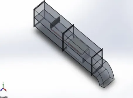
According to the design, a rectangular duct shape is used. Rectangular duct shape is easier to work with in relation to finish surface of room, but it has slightly higher friction compare with circular ducts. The model is divided into three sections to ensure easy installation & maintenance.
All the modeling has been done on solid works software. Based on the Design Calculations & some assumption the CAD model is made.
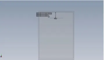
1) Model of Duct: In model 1, the fresh air from environmental is sucked by blower fan & that air will cool using thermoelectric modules. The cooled air passes through the duct & given the blade of fan using bend duct. The fan will blow the cool mixed air to the occupants & the hot air is thrown out from the duct as shown in fig 3. The system is mounted on the ceiling of the room. The room dimension is 10 × 10 × 10ft. The ceiling fan is mounted at the center of the ceiling as shown in figure.
[image:6.612.192.419.534.702.2]Fig. 2.5. Full assembly model in a room
2) Components of Model
a) Perforated Block: The block is a heat exchanger used to carry away the heat generated by the Peltier modules. The block has perforations to allow the flow of coolant through the block & bent copper tubes to join the holes for number of passes of the block. The model has been made according to the design calculations to carry the heat away & bring down & maintain the temperature at the hot junction of the Peltier module.
Fig. 2.9. Model of perforated block with bent copper tubes
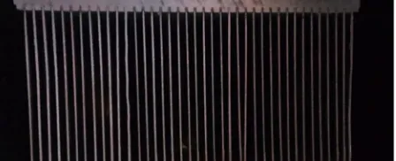
[image:7.612.224.389.275.383.2]b) Cooling Fin: The cooling fin is one of the most important component of the designed system. The cooling fin is an array of straight aluminum fins modelled as per the design calculations to enhance the surface area of the cooling side of the Peltier module. This enables to enhance the surface area of the cooling side to the flowing air in the duct.
Fig. 2.10. Model of cooling fin
[image:7.612.223.392.620.710.2]c) Radiator: Radiator used here is a cross flow heat exchanger to cool the fluid coming out of the perforated block. The radiator has been modeled as per the required surface area obtained in the design
I. Simulation Results
A. Temperature distribution across cooling fin
The figure shows the temperature distribution from base to the tip of the fins. The thermal plot shows that tip of the fin reaches 291 K when base temperature was at 280 K.
[image:8.612.180.433.160.281.2]1) Transient temperature analysis of cooling fin. The fig. shows the transient temperature analysis of fin & the temperature variation from base of the fin to the fin tip.
Fig. 2.12 Transient temperature analysis of cooling fin
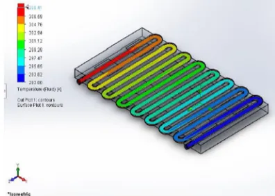
2) Thermal flow simulation of the perforated block. The figure shows the thermal flow simulation of the perforated block for coolant recirculation. The thermal plot shows the heat carried away by the coolant from the perforated block. The temperature of coolant at inlet is 298 K & that of outlet is 327 K.
Fig. 2.13. Thermal flow simulation of the perforated block
3) Pressure loss in perforated block. The fig. shows the simulation results for pressure drop across the perforated block as the coolant flows from inlet to outlet due to number of bends in the block.
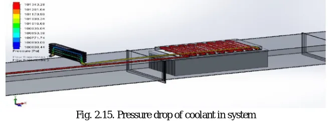
[image:8.612.205.403.352.493.2]4) Pressure drop of coolant in the system. The figure shows the simulation results for pressure drop of fluid in the system as it flows from the perforated block & the radiator.
Fig. 2.15. Pressure drop of coolant in system
[image:9.612.108.497.247.381.2]5) Pressure loss in inlet duct. The figure shows the pressure loss in the inlet duct due to the obstruction created by the cooling fin.
Fig. 2.16. Pressure loss in inlet duct
III. EXPERIMENTAL SETUP
A. Need & Background
The components have been designed, modeled & simulated for various parameters required for the final output required. Based on the models & results the components have been manufactured & assembled. The components have been manufactured taking into the design considerations & design factors.
B. Fabrication of Components
1) Peltier Module: The fig. shows the sample of Peltier module used in the system for cooling purpose in the system. It is the major component of the air cooling system & is made up of bismuth telluride semiconductor materials. The surface of the module is made of ceramic material & the all the joints inside the module are soldered joints hence handling of the modules is important. The modules are sandwiched between the cooling fin & the perforated block with cold side being on the cooling fin side. The modules are wrung using thermal compound.
[image:9.612.220.393.562.720.2]2) Specification for Peltier Module
Table 3.1
[image:10.612.208.403.393.521.2]3) Perforated Block: The figure shows the fabricated perforated block with u bend copper tubes to pass coolant from inlet to outlet of the block. The material selected for the block is Aluminium 6063T6 series as it has good thermal conductivity & light in weight. The aluminium block (360 × 190 × 20 mm) was drilled on deep hole drilling machine (diameter of 8mm). the bent copper tubes were then press fitted in these holes & sealed.
Fig. 3.2. Perforated block heat exchanger (fabricated)
4) Cooling Fin: Cooling fin is a heat exchanger used to exchange heat between air & fin surface. The cooling fin has been designed to enhance the heat transfer by increasing the surface area. The material used is aluminium HS7 series. the fins fabricated are of bonded on the base which is made by casting process. The serrations on the base were made by milling operation & the fin array is then bonded into the serrations using thermal epoxy. The total number of fins is 33 for the calculated surface area with fin height 10mm. The base has been finished by lapping process to 15 microns to have perfect contact with the Peltier modules.
[image:10.612.197.421.628.719.2]5) Radiator: Radiator is a heat exchanger used to cool the given fluid by using another fluid. The radiator used here is of cross flow type in which air is used as a cooling medium. The coolant coming out of the perforated block is at high temperature which needs to be cooled. The radiator has been procured from bajaj avenger 220 model 2005 & is made of aluminium which makes it lighter in weight & has better heat dissipation capacity.
Fig. 3.4. Radiator to drop temperature of coolant (procured)
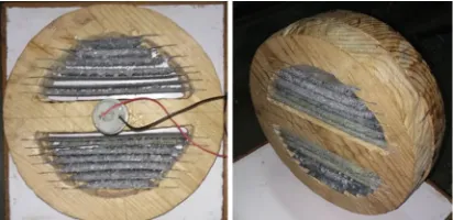
[image:11.612.210.407.131.239.2]6) Enthalpy Wheel: The enthalpy wheel is a component of desiccant based dehumidifier. It is used to dehumidify the air entering from the atmosphere into the system. The wheel is made up of wood & slots have been made to accommodate plates with desiccant (silica gel). the desiccant has been spread on GI sheets & fixed with glue. The diameter of the wheel has been taken as 240mm to mount properly on the duct. The wheel is 75mm thick to allow desiccant to absorb maximum amount of moisture from the air passing over it. The wheel is provided with constant rotation with a 3-rpm motor.
Fig. 3.5. Enthalpy wheel for dehumidifying inlet air
[image:11.612.204.410.330.430.2]7) Specification of Motor
Table 3.2
8) Pump: Pump is a device used to move a fluid by mechanical action from one part to another. The pressure & the velocity of the fluid is increased in the pump. The pump used here works on centrifugal action & hence priming is essential before starting the pump. The pump runs on direct current on 12V. The pump is procured on the basis of required flow rate (1.2 lpm).
[image:11.612.266.346.619.718.2]9) Specification of Pump
Table 3.3
[image:12.612.249.362.424.556.2]10) Heater: Heater is an electrical device that converts electrical energy into heat. A coil type heater is used in the system in the exhaust duct of the system. The main reason for employing the heater is to heat the exhaust air which would carry away the moisture from the desiccant into the atmosphere.
Fig. 3.11. Heater
11) Coolant: Ethylene glycol is used as coolant in the system for carrying away the heat generated by the Peltier modules by recirculating the coolant through the system. The coolant is mixed in the ratio of 6 parts of water to 1 part of coolant. The coolant has better heat transfer coefficient than water alone hence helps in better heat dissipation through the perforated block. It has a working temperature range of -29 ℃ to 129 ℃.
Fig. 3.12. Coolant for recirculation through system
C. Electrical Connection
[image:12.612.208.406.634.716.2]Two Peltier modules are connected in series electrically which makes one circuit, similarly eight Peltier modules are used to make four individual circuits. This has been done do divide the voltage as Peltier modules require 12 volts & the SMPS used is of 24 volts.
1) Schematic of series Connection: The fig. shows the electrical schematic of Peltier modules connected in series with each other to obtain voltage drop across the two modules connected to the power source.
Fig. 3.14. Schematic of series connection
D. Assembly of Air Cooling System
[image:13.612.149.430.207.315.2]The fig. shows the final setup of the air cooling system used to supply fresh cool air to the room.
Fig. 3.15. Final assembly
1) Construction & Working: The setup is provided with two ducts namely upper & lower duct. The lower duct takes the atmospheric air & passes it into the room after conditioning whereas the upper duct takes the hot or unconditioned air out of the room. The conditioning of the air refers to the change in temperature, velocity & humidity. The temperatures of the air are dropped using cooling setup which includes Peltier modules, perforated cooing plate, aluminum fins & the pump. The velocity of the air is changed or regulated using a fan & the humidity of air is reduced with the help of a setup called desiccant dehumidifier. The desiccant dehumidifier is a circular plate which rotates hence it is also called as enthalpy wheel. It contains metal strips with desiccant (silica gel) which absorbs moisture. The silica gel is a very good moisture absorbent & here it is used in form of beads. The wheel rotates at a very low rpm of 3.5 using a DC motor. The cooing effect is obtained using the Peltier modules which works on Peltier effect. When current is passed through a Peltier module, due to the Peltier effect one side of the module cools & other heats up. In order to use the Peltier at its peak performance its hotter side needs to be cooled hence water cooling was opted. This cooling circuit includes perforated cooling block, coolant, hoses, radiator & blowers. & to maximize the cooling effect the surface area of the modules needs to be increased which is done by using an aluminum fin. There are two processes happening simultaneously in upper & lower duct. Which are explained below:
a) Inlet Duct: The fresh air from atmosphere is sucked into the duct. It is conditioned & then passed into the room. The air is first made to pass over the enthalpy wheel which dehumidifies the air. This is done by the silica gel which is a good absorbent of moisture hence dehumidification is done. Dehumidification is also necessary so that the condensation of water can be avoided on the aluminum fins. Once the air is dehumidified it is made to pass over the fins hence the air gets cooled. This cooled or conditioned air is then passed into the room which is thrown over the ceiling fan.
b) Exhaust Duct: Upper duct handles the unconditioned air. The components inside the upper ducts are perforated cooling block, radiator, blowers & enthalpy wheel. The air inside the room is sucked in using a blower & this air is used to cool the coolant using a radiator. Then this air is thrown out of the room.
c) Reason for Rotation of Enthalpy Wheel: When air is sucked into the lower duct the air is humid. It is dehumidified using the enthalpy wheel, where silica gel absorbs the moisture. After some time there is a possibility of saturation of the silica gel it is necessary to remove the moisture from the gel. Thus, the wheel is rotated & when the silica gel plated reaches the upper duct hotter air is blown using a heater which results in evaporation of water from the gel. The wheel is rotated at a very low rpm i.e. 3.5rpm
E. Conclusion
IV. RESULT & DISCUSSION
A. Results of Simulation
[image:14.612.162.453.135.295.2]1) The fig 5.1 shows the variation of heat power pumped through cooling fin with variation of time. It is seen from the simulation results that the cooling fin requires about 4.5 minutes to reach the desired temperature for cooling the air.
Fig. Simulation result for heat power vs. time for cooling fin
B. Results of Experimental Setup
The experimental setup was tested in a room with ambient temperature as 33 0C DBT & 27.5 0C WBT. The relative humidity of the room was 68.5%.
1) The temperature of fin has been found to be 15 0C. However, the fin took around 8.5 minutes to reach 150C from room temperature.
2) The Coolant temperature at outlet of perforated block has been found to be 55 0C.
3) The inlet conditions of the air into the room has been measured using a sling Psychrometer & the conditions have been found to be 260C DBT & 210C WBT. A dehumidification of 2% has been achieved. The outlet conditions have been plotted on a psychrometric chart as shown in the figure.
Fig. Psychrometric chart showing cooling & dehumidification
C. Power Consumption
1) Each Peltier modules consume 12V & 2.5 ampere. Thus, the electrical power output being 30 W. The total circuit of 8 Peltier modules consume 240 W.
2) The Auxiliary items such as blowers, pump, motor combined consume 60W of electrical power.
[image:14.612.149.462.443.614.2]V. CONCLUSION
The air cooler using Peltier modules is a device which uses the principle of Peltier effect combined with mechanical systems to cool the air flowing through the system to give the desired cooling effect. It is a flexible system which produces cooling as well as heating with a simple polarity switch. This is an alternative system for air conditioners which eliminates the use of compressors & refrigerants. As well as being portable & compact device, the electrical power through the system is accurately controlled through a switch mode power supply. This enables the system to produce the required cooling on the fins to cool the air in turn flowing through it.
An innovative concept for air cooling was presented. After a short overview of today’s electronic systems using Peltier modules for cooling electronic cabinets. With the proposed design it is possible to produce cooling effect. However, with the use of proper controllers it is possible to control temperature of air accurately. Finally, the feasibility of system was demonstrated using the blower for air flow through the duct.
The project work & testing show that this setup solves the problems such as global warming potential, ozone depletion potential thereby exhibiting a good integrated result. This system requires low maintenance, does not require skilled labour, has longer life span & requires less capital investment. It has low running cost & can be implemented to small office cubicles. The entire system can be automated which gives better control & ease of operation.
VI. FUTURE SCOPE
A. Design of a shell & coil type of heat exchanger to cool the recirculating coolant more efficiently & thus dissipate the heat from the Peltier
B. Design of a feedback controller device which would give the real time information about the performance of the Peltier modules as well as of other auxiliary components
C. Temperature regulation of the outlet air using a wireless remote control. D. To run the setup using solar panel as all the components run on DC supply. E. Using the setup for heating purpose by reversing the polarity of the modules.
REFERENCES
[1] Suwit Jugsujinda, Athorn Vora-ud, & Tosawat Seetawan” Analyzing of Thermoelectric Refrigerator Performance”, Procedia Engineering 8 (2011) 154–159, Thail&.
[2] Matthieu Cosnier, Gilles Fraisse, Lingai Luo,”An experimental & numerical study of a thermoelectric air-cooling & air-heating system”, international journal of refrigeration 31 (2008) 1051–1062
[3] D. Astrain, A. Martínez, A. Rodríguez,“Improvement of a thermoelectric & vapour compression hybrid refrigerator”, Applied Thermal Engineering 39 (2012) 140-150, Spain.
[4] S.B. Riffat , Guoquan Qiu,”Comparative investigation of thermoelectric air-conditioners versus vapour compression & absorption air-conditioners”, Applied Thermal Engineering 24 (2004) 1979–1993, UK.
[5] Tianhe Han, Guangcai Gong, Zhongbin Liu, Ling Zhang, “Optimum design & experimental study of a thermoelectric ventilator”, Applied Thermal Engineering 67 (2014) 529-539, China.
[6] Ahmed Khoshnevis, Faramaz Talati, Maziyar jalaal, “experimental setup on Heat transfer enhancement of slot & hole shaped perforations in rectangular ribs of a 3D model”.
[7] R.S Khurmi & J.K Gupta, “Refrigeration & Air Conditioning”, 5th edition. [8] S.P. Venkateshan, “Heat transfer”, 2009.
[9] https://www.electronics-cooling.com/2006/11/the-seebeck-coefficient/
[10] https://thermal.ferrotec.com/technology/thermoelectric-reference-guide/thermalref01/ [11] https://thermal.ferrotec.com/technology/thermoelectric-reference-guide/thermalref02/ [12] http://www.heatsink-guide.com/Peltier.htm
![Fig. 1.1. Peltier Effect[10]](https://thumb-us.123doks.com/thumbv2/123dok_us/1234923.649022/1.612.208.405.584.685/fig-peltier-effect.webp)
![Fig. 1.2. Working principle of peltier device[13]](https://thumb-us.123doks.com/thumbv2/123dok_us/1234923.649022/2.612.187.431.465.593/fig-working-principle-of-peltier-device.webp)