Abstract— Remote laboratories are ideal for applications where the experiment is inaccessible, remote from the student or extremely expensive such that it has to be shared between different institutions. This paper describes an experiment that uses a compound pendulum controlled by a variable speed fan in order to allow the students to remotely learn the fundamentals of system modeling and automatic control. Details of the software platform, the web-page publishing and the internet connection mechanism are given in order to show the problems overcome to allow the system to be used successfully.
Index Terms— Remote laboratories, e-learning, engineering education, control system principles.
I. INTRODUCTION
EMOTE laboratories provide remote access to physical real laboratories allowing the student to carry out an experiment on a physical system, observe its operation, retrieve the results and analyse them. They provide a compromise between direct access to real physical systems and the use of virtual systems. They offer the student the reality of real systems, but solve the problem of access caused by distance, inaccessibility or other reasons. They have an advantage over virtual systems in that the student can experience the real response of a physical system with all its practical aspects. Examples of such systems are discussed in [1], [2] and [3].
This paper discusses a remote lab developed in order to allow the student to learn the principles of automatic control, by remotely controlling a compound pendulum driven by a fan with feedback provided by a shaft encoder.
II. APPLICATIONS OF REMOTE
LABORATORIES
Remote laboratories are ideal in the following situations: a) The student is in a remote location away from the
laboratory (e.g., student’s residence remote from the institution; student located in a different country).
Manuscript received March 18th 2011; revised April 16, 2011.
Lutfi Al-Sharif is with the University of Jordan, Mechatronics
b) The laboratory or the experiment is a scarce resource (e.g., where the cost of the laboratory is very high and cannot be afforded by all institutions). In such a case a number of institutions can pool their resources where each institution specialises in one specific discipline and allows other institutions to access it remotely.
c) The usage of the laboratory is hazardous either due to its nature and content or due to the risk of misuse by students (e.g., laser laboratory).
d) The facility is inaccessible or accessible with great difficulty (e.g., deep underground facility; high security facility).
e) The facility can only be located in a specific geographical location due to its uniqueness or special features [3] (e.g., very hot location; very cold location; outer space).
f) In cases where extended hours access is required (e.g., 24 hour access) but where security does not permit it. The extended hours access can either be needed for convenience or to increase the usage of the scarce facility.
This paper describes a practical system built to allow the students to remotely carry out a set of experiments to understand the basic principles of control systems. A website is built which takes the students through a set of logical steps combining theoretical background and practical assignments. The physical system consists of a compound pendulum fitted at its lower end with a fan the speed of which can be controlled using pulse width modulation. A shaft encoder is used to feed back the position of the pendulum to the controller. The software uses NI LabVIEW as a basis for building the interface and publishing the web-page, an example of which is also shown in [4].
The student starts by arriving at a model of the system and then building a PID controller for the system and tuning it. The response from the system can be downloaded by the student and analysed.
III. IMPORTANT CONSIDERATIONS
There are two options regarding the running of the real physical system. Under the first option, the software
Teaching Control System Principles Using
Remote Laboratories over the Internet
Lutfi Al-Sharif, Ashraf Saleem, Walid Ayoub, and Mohammad Naser
significant delay will be introduced into the control loop that will completely ruin the validity of the model and the possibility of correctly controlling the physical system. This option is not practical, as it is not realistic to expect the user (in fact all users) to have a high speed internet connection and a fast PC with an advanced specification. Even where a high speed internet connection is available, it cannot be used as part of a real time control due to the random and erratic behavior of the internet connection.
The other option involves installing the real time software controlling the real physical system on the server. Under this scenario, the user does not require a PC with a high specification or a high speed internet connection. Furthermore, the internet reliability will not affect the real time control of the system since the user PC is not closing the loop in this case. The remote PC merely provides the parameters to be used in the control (e.g., P, I and D settings) to the server which in turn closes the control loop.
It is important to take the following points into consideration when developing remote laboratories:
a) The speed of the internet connection connecting the user computer to the server controlling experiment can be limited and thus should not form part of the closed loop control system.
b) The real time controller and software must reside on the local server that is directly connected to the physical system that is controlled. This ensures that the local server can directly control the physical system and gather data.
c) The main role of the user is to set up the experiment and load any algorithm or parameters, and then just instruct the server to run the experiment.
d) It is very useful to provide visual feedback from the physical experiment back to the remote user. This enhances the user’s experience and makes it more realistic.
At the core of the remote laboratory setup is the experiment setup, which is achieved by selecting the appropriate hardware kits and required software components
IV. E-LAB FOR TEACHING AUTOMATIC CONTROL COURSE
Any traditional automatic control course starts with system modeling principles, and then moves to first order, second order and higher order systems response analysis. It can be advantageous to show students through e-labs how these systems respond to different inputs i.e. the open loop behavior of the system.
After understanding the open loop behavior of the system, instructor can move to control system design including PID control, lead compensators and lag compensators. Instead of having simulation demonstration only, the instructor can have practical control system design through e-lab which allows students to practically see the system behavior. This will also help students to understand how the controller can significantly change the system response in terms of overshoot percentage, rising time, settling time, and steady state error.
Moreover, e-labs will be very useful when explaining system stability and disturbance rejection which are hard to be comprehended without practical experiments. E-labs can be also utilized when control system design by root locus is considered. Here, student can observe how changing zeros, poles, and gain values will affect the practical system. Finally, e-labs will be very helpful in frequency domain analysis spatially when changing the phase and gain margins of the system through the designed control system. From an administrative perspective, e-labs can be easily scheduled to be utilized by a number of instructors in different departments and universities. Under this scenario, a large number of different experiment kits can be shared and utilized in different universities. The following sections explain an experimental setup that was developed and tested for different scenarios and two case studies for first order system and second order systems.
V. EXPERIMENTAL SET UP
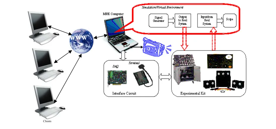
As shown in Fig. (1), e-lab environment, the clients access the control panel on the server computer through web browsers. The physical experiment, sensors and actuators, are interfaced to the server computer through a data acquisition card and a webcam to provide visual feedback. In order to read, store, and analyse the data, a programming tool needs to be installed on the server computer.
The server computer is given a static local IP address by the router. The router must be assigned an external static IP address in order to make it possible for client computers to connect to the router through the internet.
Development software is needed to be installed in the server computer to acquire, process, and send signals to the interfaced experiment. In this context, LabView and MATLAB are the most used development software. In this work, LabView is employed since it is more powerful in generating graphical user interfaces, web publishing and creating data bases to store the results.
Fig. (1) General structure for the implemented e-lab
On the client side, it is necessary to have the free LabView run-time engine installed on the computer. When a remote viewer logs onto the lab with the appropriate URL address, the LabView front panel will appear in the browser, or reroute the user to install the run-time engine from the National Instruments Web site. Installing the free run-time engine does not require the client to have Lab View software installed in his/her own personal computer; this is an attractive feature of using Lab VIEW as development software on the server computer. After installing the run-time engine, the client should be able to connect easily to the Front Panel by clicking on the specific link.
VI. CASE STUDIES
This section presents two case studies on first and second order systems. The objective of these case studies is to show the feasibility of using remote labs in control courses.
A. RC circuit experiment (First order system)
This experiment is easy and simple to implement, it is a resistor and capacitor connected in series. The resistor chosen value is 100 kΩ and the capacitor value is 1 µF. A simple program is implemented using LabView to perform different experiments. Fig (2) shows the program that generates two types of input, a square waveform and a sinusoidal waveform. The output of the circuit is fed into a DAQ assistant block programmed to acquire analog voltage.
Fig. (2) RC Experiment Block Diagram in LabView
The step response appears on the remote panel as shown in Fig. (3).
Fig. (3) RC Circuit Step Response
Another experiment that is carried out involves the system Clients
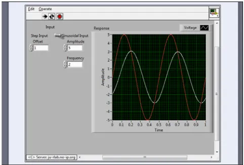
[image:3.595.49.520.51.272.2] [image:3.595.303.554.300.448.2] [image:3.595.304.555.512.684.2]Fig. (4) RC Circuit Sinusoid Response
B. Compound Pendulum Mechatronics System (Second
order system)
The compound pendulum mechatronic system is developed by a group of final year students in the Mechatronics Engineering Department at the University of Jordan. The idea of this system is to fix a motor-propeller on the edge of a pendulum which provides the pendulum with a thrust force in order to control its angle (θ). Fig (5) shows the developed system.
(a)
(b)
[image:4.595.45.286.49.212.2]In this experiment the students can test the open loop response of the system as well as the closed loop response using PID control algorithm. The front panel of this experiment is shown in Fig (6). Through this panel the user can select the control mode whether it is open loop or closed loop. In the case of closed loop situation the user can select the PID parameters.
Fig. (6) Front panel design
In order to test the open loop behavior of the system, a 4 volt step is used to excite the system. The system output is as shown in Fig. (7). The student can notice the oscillation around the set value with a long settling time as well as a high overshoot. Using remote lab will show students this response physically through the fixed camera on the system.
Fig. (7) Open Loop Step Response
After understanding the open loop response, students will be introduced to the design of a controller for this system (PID in this case study). Fig. (8) shows the closed loop response of the system after tuning the PID controller through the front panel. Comparing the results from the open and closed loop responses of the system will facilitate the understanding of control system influence on the system behavior.
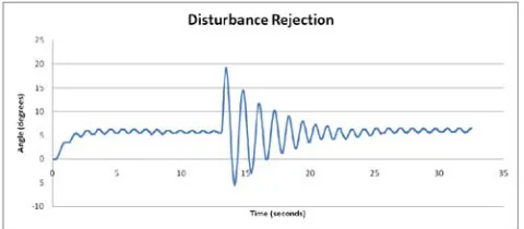
One more experiment that can be performed using this setup is the concept of disturbance rejection. While the system showed good set point tracking performance, the disturbance rejection performance was not as desired, and that is expected because the design was based on a step
Fig (8) closed loop response with θ = 8.5 as a set point.
Fig. (9) System step response with disturbance rejection
VII. CONCLUSIONS
Remote labs are essential tools to allow students to access scarce resources or solve the problems of distance between the students and the laboratories.
A compound pendulum physical experiment that is controlled by a dc power fan with feedback using a shaft encoder has been built and remotely controlled via the internet.
A number of consecutive experiments have been set up to allow the students to understand the basics of modeling and control of a simple first order system and a second order system.
The control should be done from the local server that is directly connected to the physical experiment. The remote PC terminal sends the required parameters to the local server which then runs the experiment and sends the results back to the remote PC.
REFERENCES
[1] Rafael Puerto, Luis M. Jimenez, Oscar Reinoso, Cesar Fernandez, Ramon Neco, “Remote Control Laboratory Using Matlab and Simulink: Application to a DC Motor model”, 2nd IFAC Workshop
on Internet Based Control Education (IBCE'04), Grenoble, France,. September 5-7, 2004.
[2] Marco Casini, Domenico Prattichizzo, Antonio Vicino, “E-Learning by Remote Laboratories: A New Tool for Control Education”, 6th IFAC Symposium on Advances in Control Education, Oulu, Finland, June 2003.
[3] I. Michaelides, P. Eleftheriou, K. Economides, “Solar Energy e-learning laboratory – Remote Experimentation over the Internet”, International Journal of Online Engineering, Vol 1, No 2 (2005). [4] W. Tlaczala, M. Zaremba, A. Zagorski and G. Gorghiu, “Virtual
[image:5.595.314.553.51.172.2] [image:5.595.45.285.142.312.2] [image:5.595.305.545.208.313.2] [image:5.595.48.289.429.562.2]