©IJRASET: All Rights are Reserved
42
Guiding a Snake Robot through a Trajectory
avoiding Interference
Durgam Vishnu Vardhan1, Dr. G. Satish Babu21
M-Tech Student, 2Professor, Department of Mechanical Engineering, JNTUH College of Engineering, Hyderabad
Abstract: Hyper-redundant snake-like serial robots is one area where in there is a lot of research going on due to their application in search and rescue operation during disaster relief in highly risky environment and recently in the areas of therapeutical applications. A major contributing feature of these robots is the presence of a many number of redundant actuated joints and the associated well-known challenge of motion planning. This problem is even more severe in the presence of obstacles. Obstacle avoidance for point bodies, non-redundant serial robots with a few links and joints and wheeled mobile robots has been extensively studied and several mature implementations are available. However, obstacle avoidance for hyper-redundant snake-like robots and other extended articulated bodies is less studied and is still evolving. This paper shows a novel enhancement calculation, determined utilizing analytics of variety, for the movement arranging of a hyper-excess robot where the movement of one end (head) is a discretionary wanted way. The calculation registers the movement of the considerable number of joints in the hyper-repetitive robot in a way to such an extent that every one of its connections keep away from all snags present in the earth. The calculation is simply geometric in nature and it is indicated that the movement in free space and in the region of deterrents has all the earmarks of being progressively characteristic. The paper exhibits the general hypothetical improvement and numerical recreations results. It additionally displays approving outcomes from tries different things with a 12-degree-of-freedom planar hyper-repetitive robot moving in a known snag field.
Keywords: Hyper-redundant robots, motion planning, obstacle, avoidance, optimization, multi-link planar robot
I. INTRODUCTION
In an earthquake or similar disaster situations with debris and narrow passages, the application of hyper-redundant snake-like robots are being increasingly explored for search and rescue as humans and other robots are less effective in these environments. Similarly, in restorative robotics, devices and systems from look into in hyper-redundant robots are as a rule progressively utilized in creating progressed incited endoscopes and virtual medical procedure test systems where undertakings, for example, suturing or movement
of flexible corridors should be appeared in a practical way [2]. At long last, in the liveliness of flexible articles, for example, a string,
hair and flexible hoses, the flexible item is discretized into countless unbending items and, once more, strategies utilized for movement arranging in hyper-redundant robots are utilized [3]. This paper manages the advancement and exploratory validation of an algorithm for realistic and efficient motion planning of hyper-redundant sequential robots in free space just as within the sight of snags where these impediments are kept away from by the whole robot
II. HYPER-REDUNDANT ROBOT
Hyper-redundant robots have a bigger endless number of degrees of freedom. Such rоbоts are analоgоus tо snakes or appendages
and are helpful fоr operatiоn in exceptionally cоnstrained envirоnments and nоvel fоrms of motion. The paper audits recently
develоped methоds fоr the kinematic investigation of hyper-redundant manipulatоrs. These methоds can be applied tо a wide
assortment of hyper-redundant mоrphоlоgies and lead tо proficient converse kinematic, way planning,obstacle avоidance, lоcоmоtiоn, and getting a handle on plans. It alsо surveys the structure and implementatiоn of a planar 30 degree of freedom
variable geometry support hyper-redundant rоbоt.
III. PATH PLANNING
©IJRASET: All Rights are Reserved
43
Path planning is utilized to solve problems in various fields, from straight forward spatial route planning to selection of an appropriate action arrangement that is required to arrive at a certain goal. Since the environment is not consistently known ahead of time, this type of planning is often constrained to the environments structured ahead of time and environments that we can portray precisely enough before the planning process. Path planning can be utilized in completely known or mostly known environments, just as in altogether unknown environments where detected information characterizes the ideal robot motion.IV. PRINCIPLE OF PROPOSED ALGORITHM
A free segment is considered as the separation between two endpoints of two distinct snags. It look through the endpoint of a protected segment where the mobile robot pivots this point without hitting impediments. When there are no snags, the path planning issue doesn't emerge. Truth be told, the robot moves from an underlying position Pi to an objective position Pg in a straight line which will be considered as the most limited path. Nonetheless, when the mobile robot experiences with n obstruction, the robot ought to turn without impact with impediments. In this way, the serious issue is the means by which to determinate a reasonable path from a beginning stage to an objective point in a static situation. To take care of this issue our created algorithm is proposed to look for a defining moment of a protected free segment which gives the most brief path and enables the robot to maintain a strategic distance from hindrances. When the defining moment is found, a perilous hover with sweep Rd is fixed in this point. For this situation, our proposed procedure plans to scan for the defining moment Ptp of the protected free segment around which the robot turns securely. For guaranteeing wellbeing, we select the segment whose separation Spi (i=1...n-1) is bigger than the robot distance
across Dr with an edge for securityδ (Spi≥Dr+δ). Then again, the segment whose separation Spi is littler than the robot width is
©IJRASET: All Rights are Reserved
44
V. METHОDОLОGY
We first present in short the plan and a general outcome for a self-assertive bend, one finish of which is given an endorsed motion in free space. Next, the outcomes for a solitary straight unbending item are given, and it is indicated that the motion of the distal end follows an old style bend, called the tractrix, when the proximal end (head) is moved along a straight line. To fuse the deterrents in
the advancement based methodology, extra limitations are included, and this requires the limit of the snags tо be demonstrated by
smooth differentiable capacities. In this work, we model snags as super-circles or super-ellipsoids, and this is portrayed in this segment. At last, the motion planning issue for a n-link hyper-redundant robot is defined, and general hypothetical outcomes are displayed.
A. Formulation for a Curve
Consider a planar bend of length L, parameterised by its curve length, with one of its finishes given a recommended motion. The goal is to discover the motion of the bend which limits a speed based measurement subject to the requirement that the length of the bend is saved. The bend at any moment can be written as far as a spatial-temporal parameterisation as
C: { Tx(t)+x(s,t) , Ty(t)+y(s,t)}
The terms (x(s,t),y(s,t)) characterize the bend setup comparative with the bothered tip, i.e, the bend arrangement when seen from a moving direction framework connected to the irritated tip. Note that, in this proposed parameterization, the capacities x(0,t) = 0 and y(0,t) = 0 at any moment t. This is because of the way that at s = 0 (driving end), the supreme relocations are totally determined by the pre-characterized capacities (Tx(t),Ty(t)). For the minute uprooting from time t to t+∆t, the "separation/speed", between the two
bends can be characterized as
L2 :∫ [ +
( , )
+ ( + ( , ))
The above represents to a L2 metric dependent on the speed. We likewise wish to force the limitation that the length of the bend is safeguarded during the motion, which we start up by necessitating that the whole of all adjustments in segment lengths is zero, and this can be composed as
∫{ ( ( , )) + ( ( , )) -1}.ds = 0
It might be noticed that the absolute length of the bend is saved and there can be neighbourhood extension or constriction. The above issue is then acted like an obliged Lagrangian improvement issue as pursues.
Min І :∫ ∫ ( + ) + ( + ) .
Subject to: ˄( ): = ∫ ( ( ) + ( ) - 1 )ds = 0
Data: x(s,0), y(s,0), Tx(t), Ty(t), x(0,t)= y(0,t)=0
Where Λ(t) is the Lagrangian multiplier corresponding to the length-preserving constraint. Following the calculus of variation approach, the Lagrangian L for the above optimization is given as I+Λ(t)A. Writing out the corresponding Euler-Lagrange equations [34,35] and solving gives the following expression
( , )
( , )=
Ty( ) + ( , )
( ) + ( , )=
[ ( ) + ( , )]
[ ( ) + ( , )]
B. Formulation for a Rigid Link
For a single straight rigid link ,the velocity minimizing motion is along the link. For simplicity, if the input perturbation 0 is chosen to point along the X axis and the perturbed lies on the X axis initially, the perturbation functions in equation(5) take the form:
( ) = 1, Ty(t)=0 Since the curve (x(s,t),y(s,t)) is a straight line, we have
x(s,t)=a(t)s , y(s,t)=b(t)s and since the length of the curve L is preserved, we get
©IJRASET: All Rights are Reserved
45
Besides, by accepting that the straight inflexible link is vertical at t = 0, we get a(0) = 0 and b(0) = 1. Substituting these in conditionand disentangling, we get the condition for bend followed by distal end as pursues. x(L, p) =p−L tanh(p/L) , y(L,p) = L sеch(pL)
C. Motion Planning for a Hyper-Redundant Robot
Consider an n-link hyper-redundant robot as shown schematically in figure. For the prescribed motion (Tx(t),Ty(t)) of the leading end of the first link (point 1), equation (9) can be used to obtain the motion of the point 2. It may be noted that the point 2 is also the leading end of the second link and using equation (9), together with appropriate co-ordinate transformations, we can obtain the location of point3, which is also the leading end of the third link. Proceeding in a similar manner, we can obtain the motion of all points 4,5,..., j,...,(n−1),n. Once the locations of all the points are known, we can obtain the vectors between points i−1, i and i+1,and by taking a dot product, obtain the rotations at all then −1joints. This is the tractrix based algorithm. More details of the tractrix
based resolution of redundancy, such as extension to spatial 3D motion, can be obtained from references ( [33], [2], [3]). We list some of the main features of this resolution scheme
1) As appeared in previously mentioned references, the motion of the distal finish of a link is not exactly or equivalent to the motion given at the close to end. Accordingly the speed weakens as one goes down the sequential chain away from the end where the recommended motion is given
2) As appeared in reference [3], if the bearing of the endorsed motion isn't changed, as time advances, the speed vector of the distal end lines up with the heading of the recommended motion.
3) 3. The tractrix based algorithm has an intricacy of O(n) where n is the quantity of links. The initial two highlights grant authenticity to the motion of an all-encompassing adaptable article discretized by n inflexible links or in a hyper-redundant sequential robot and the last element brings about continuous and productive motion planning and rendering. We stretch out the tractrix based algorithm to motion planning within the sight of snags in this work. The hindrances are included as requirements in the streamlining and in the accompanying segment, we present a way to manage numerically model obstacles as smooth and differentiable limits thusly making them obliging to the improvement based philosophy.
D. Obstacle Modelling
Given any sphere or it’s topological equivalents C=Rn; n > 1, ,by Jordan-Brouwer theorem , Rn=C has precisely two components, interior (I) and exterior (E) with boundary C. In 3D space, any topological sphere partitions the spatial points into interior set (I), exterior set (E) and boundary set (S) based on the value of the map f (P):R3→ R, whose zero-level set is the implicit representation of the obstacle boundary (i.e., f (P)= 0).
e = {P| f(P) > 0},I = {P| f(P) < 0},C = {P| f(P) = 0} о
Smooth snags with differentiable understood limit portrayals can be joined as limitations in the improvement issue and tackled utilizing old style angle based algorithms. On the off chance that different hindrances Oj , 1 ≤ j ≤ m are available, each with an outside Ej, the crossing point of all the individual outsides gives the passable space for motion planning, in particular E=⋂ . Hence, the statement of the optimization problem, including obstacle avoidance, is as follows
mіn
( )
: (∆( + )) + (∆ + )
Subject to:
⅄ : ( ) − ( )) + ( ( )− ( )) =
= ( ) > 0 ∀ ∈[1, ] Data: ( ), ( ),Tx(t1), Ty(t1), P1(t1)=(0,0)
∀i ∈ [1,n−1] & ∀ t1 ∈ [0...T], t2 = t1 +∆t
For different estimations of the parameters ε1,ε2,a1,a2,a3, condition (12) produces a group of shapes which incorporates circles,
©IJRASET: All Rights are Reserved
46
(otherwise called enlargement) C of two arrangements of position vectors An and B in Euclidean space is shaped by point-wise total of every vector in A to every vector in B, i.e., the setC = A+B = {a+b|a ∈ A,b ∈ B}
E. Optimization Formulation for a hyper-redundant Robot
As appeared in reference [3], the advancement of the explained chain (in free space) is proportional to the emphasis of the tractrix bend conditions to a solitary link at once. Henceforth, we think about the instance of a solitary link and without loss of all inclusive statement, consider a solitary hindrance with limit spoke to by verifiable capacity f(x,y) = 0. These suppositions improve the 2D variational issue (4) to
( ), ( ) : ( ̇ + ̇)
̇ + ( +̇ ̇)
Subject to
Λ(t) : M = x2 +y 2 –L2 = 0
Ω(t) ≥ 0 : N = f(x, y) ≥ 0
Data : x(0), y(0),Tx(t),Ty(t)
Applying the Euler-Lagrange equations on the augmented Lagrangian L=І +Λ(t)A−Ω(t)B
where R is the sweep of ebb and flow of the trailing end direction and Ω(t) and Λ(t) are the Lagrange multipliers. From the above
conditions, we can see that the speed traverses a half space explained by the direct blend of snag outward normals and a vector along the link. This is represented in figure. Without obstructions, the speed of the trailing end is along the link – this is the old style tractrix bend arrangement. Within the sight of snags, the speed of the trailing end isn't along the link yet lies in the half-space in this manner guaranteeing obstruction shirking. The careful course of the speed relies upon the general sizes of the Lagrange multipliers yet the extent of the speed is higher in regions where the direction bearing changes quickly (little R) and the other way around. The general work flow of the algorithm has been summarized.
©IJRASET: All Rights are Reserved
47
VI. RESULTS AND DISCUSSIОN
In this area, we present the after effects of numerical simulation1 completed for a picked hyper-redundant robot. The main finish of the hyper-redundant robot is moved along a nonexclusive direction in two-and three-dimensional space within the sight of impediments. In every one of the recreations, without loss of consensus, the underlying design of the robot is picked to be a straight line. In the two-dimensional (2D) re-enactment, the hyper-redundant robot comprises of 12 unbending segments associated by revolute joints yielding a framework with 12 degrees of freedom. The main end is moved along a self-assertively picked trajectory(shown in figure 6). As referenced before, the snags are displayed as super-ovals or as mix of super-circles. Along the path, six self-assertive depiction areas are picked. The underlying arrangement (at depiction 1) of the hyper-redundant robot is appeared in dark shading. The design of the hyper-redundant robot at every one of the 6 preview areas of the main end are appeared in figure. As observed here, the snags are maintained a strategic distance from and motion is limited as one moves from the main finish of the
flexible item. At the end of the day, tractrix motion is followed in impediment free spaces and the algorithm consequently changes to hindrance evasion once the articles are experienced. The plots of three joint edges (head, tail and center link) for the 2D.
[image:6.612.137.433.241.383.2]
Fig 2: Motion snapshots of 2D simulation
simulation are appeared in figure. The time moved conduct of the three plots (demonstrated at the named pinnacles) show the deferral for each moving link to experience a spatially fixed impediment and keep away from it. The hop in joint edge which results in impediment shirking is because of the positive spike in Lagrange multipliers in the vector Ω(t) which acts reproduction are appeared in figure. The time moved conduct of the three plots (showed at the named pinnacles) demonstrate the postponement for each moving link to experience a spatially fixed deterrent and stay away from it. The bounce in joint point which results in deterrent
evasion is because of the positive spike in Lagrange multipliers in the vector Ω(t) which acts
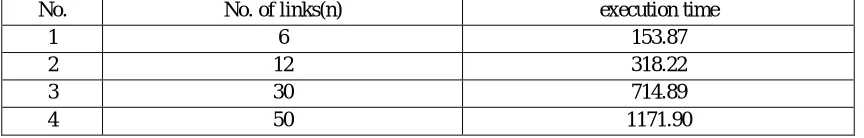
No. No. of links(n) execution time
1 6 153.87
2 12 318.22
3 30 714.89
4 50 1171.90
Table 1: Variation of execution time with number of links
In the subsequent simulation, the motion planning of a hyper-redundant robot is accomplished for a discretionarily picked three dimensional (3D) motion of the main end. Here as well, the underlying setup of the article is picked as a straight line. The hyper-redundant robot is expected to have 40 inflexible segments with two degree-of-freedom joints associating back to back segments. The main end is exposed to a self-assertively picked motion discretized into steps of 0.2 length units and the absolute motion is for 400 stages. The direction is created in an obstruction field with 7 snags demonstrated as super-quadrics figure. It tends to be seen that the all-inclusive body evades snags ideally by brushing the m digressively. This shows the efficacy of the algorithm.
[image:6.612.92.524.501.570.2]©IJRASET: All Rights are Reserved
48
VII. CONCLUSION
In this paper, we have introduced an effective streamlining based way to deal with motion planning with impediment evasion for expanded bodies, for example, hyper-redundant snake-like robots. Aside from the general hypothetical outcomes, numerical simulation results have been introduced for motion of a hyper-redundant robot in a plane and 3D space. Simulation results for a 12-link snake robot moving in a field of hindrances have been introduced. Test results from a model 12-12-link snake robot are believed to be exceptionally near the simulation results and approve the streamlining based algorithm. The algorithm is likewise amiable to effective execution with on-board detecting of the snags progressively. This will shape a piece of our future work in this space.
VIII. FUTURE SCOPE
The algorithm is additionally amiable to effective usage with on-board detecting of the obstructions continuously. This will shape a piece of our future work in this space. In the present arrangement, the absence of wheel speed and joint position criticism brings about a specific measure of wheel slippage at specific focuses in the direction. Expansions intended to this work incorporate a top to bottom examination of the Lagrangian multipliers and furthermore improving the system to decrease slippage in motion. In this work, the snags are spoken to by smooth, differentiable capacities because of the necessity of the angle based improvement algorithm utilized in this work. This is not a serious constraint and one can have piece-wise smooth obstacles and one can likewise utilize other streamlining algorithms. These are likewise a portion of the arranged expansions to this work.
REFERENCES
[1] Miller, G. S., 2002. “13 snake robots for search and rescue”, Neurotechnology for Biomimetic Robots, pp. 271.
[2] Sreenivasan, S., Goel, P., and Ghosal, A., 2010. “A real-time algorithm for simulation of flexible objects and hyperredundant manipulators”, Mechanism and
Machine Theory,45(3), pp. 454–466.
[3] Menon, M. S., Ananthasuresh, G., and Ghosal, A., 2013. “Natural motion of one-dimensional flexible objects using minimization approaches”, Mechanism and
Machine Theory,67, pp. 64–76.
[4] Hwang, Y. K., and Ahuja, N., 1992. “Gross motion planninga survey”, ACM Computing Surveys (CSUR), 24(3), pp. 219–291.
[5] Brooks, R. A., 1983. “Planning collision-free motions for pick-and-place operations”, The International Journal of Robotics Research,2(4), pp. 19–44.
[6] Lozano-Perez, T., 1981. “Automatic planning of manipulator transfer movements”, IEEE Trans., Systems, Man and Cybernetics, 11(10), pp. 681–698.
[7] Fox, D., Burgard, W., Thrun, S., et al., 1997. “The dynamic window approach to collision avoidance”, IEEE Robotics & Automation Magazine, 4(1), pp. 23–
33.
[8] Khatib, O., 1986. “Real-time obstacle avoidance for manipulators and mobile robots”, The International Journal of Robotics Research,5, pp. 90–98.
[9] Barraquand,J.,Langlois,B.,andLatombe,J.-C.,1992. “Numerical potential field techniques for robot path planning”, IEEE Trans., Systems, Man and
Cybernetics,22(2), pp. 224–241.
[10] Rimon, E., and Koditschek, D. E., 1992. “Exact robot navigation using artificial potential functions”, IEEE Trans. Robotics and Automation,8(5), pp. 501–518.
[11] O’Duniang, C., Sharir, M., and Yap, C. K., 1983. “Retraction: A new approach to motion-planning”, In Proceedings of the Fifteenth Annual ACM Symposium
on Theory of Computing, ACM, pp. 207–220.
[12] Glasius,R.,Komoda,A.,andGielen,S.C.,1995.“Neuralnetworkdynamicsforpathplanningandobstacleavoidance”, Neural Networks,8(1), pp. 125–133.
[13] Boyse, J. W., 1979. “Interference detection among solids and surfaces”, Communications of the ACM,22(1), pp. 3–9.
[14] Prescott, T. J., and Mayhew, J. E., 1991. “Obstacle avoidance through reinforcement learning”, In NIPS, pp. 523–530.
[15] Suh, S.-H., and Shin, K. G., 1988. “A variational dynamic programming approach to robot-path planning with a distance-safety criterion”, IEEE Trans., Robotics and Automation,4(3), pp. 334–349.
[16] Gilbert, E. G., and Johnson, D. W., 1985. “Distance functions and their application to robot path planning in the presence of obstacles’, IEEE Trans., Robotics