Abstract— Magnesium alloys are becoming increasingly popular in industrial applications due to their low density and high specific strength. The improvements sought in the formability at ambient temperature and fracture resistance of magnesium alloy AZ31B can be attained through the use of Severe Plastic Deformation (SPD). In order to investigate the deformation response of this material, in situ three-point bending test was performed on a sample extracted from a plate subjected to SPD by constrained groove pressing (CGP). High-energy synchrotron X-ray diffraction was used to examine the lattice strains across the sample. It revealed that significant tension-compression asymmetry is observed for some grain groups. Twinning deformation mode is observed under compressive loading differs from other modes. Additionally, it has been shown that plastic deformation proceeds more readily within grains which experience loading parallel to the basal plane. This is in contrast to the grains whose c-axis is aligned with the loading direction. Stress-strain curves were obtained from XRD and they agree well with results from mechanical test.
Index Terms — Magnesium alloy AZ31B, Severe Plastic Deformation, Groove Pressing, Crystal Lattice Strain, Synchrotron X-ray Diffraction
I. INTRODUCTION
HANKS to their low density and high specific stiffness and strength, magnesium alloys have great potential for application in many industrial fields such as lightweight automotive design, electronics packaging, airplane manufacturing etc., with the aim of reducing load and emissions, and saving energy. Magnesium alloys shaped in the form of thin sheet are particularly interesting in terms of low mass design of components such as covers, seat frames and body panels [1]. One of the drawbacks of manufacturing with magnesium alloys is the low formability at ambient
Manuscript received January 5, 2016; revised January 27, 2016. This work was supported in part by the EU FP7 project iSTRESS (604646)
Hongjia Zhang is with Department of Engineering Science, University of Oxford, Oxford, OX1 3PJ, UK (email: [email protected]).
Kai Soon Fong is with Singapore Institute of Manufacturing Technology, 71 Nanyang Drive, Singapore 638075 ([email protected]).
Xu Song is with Singapore Institute of Manufacturing Technology, 71 Nanyang Drive, Singapore 638075 ([email protected]).
Siqi Ying is with Department of Engineering Science, University of Oxford, Oxford, OX1 3PJ, UK ([email protected]).
Enrico Salvati is with Department of Engineering Science, University of Oxford, Oxford, OX1 3PJ, UK ([email protected]).
Tan Sui is with Department of Engineering Science, University of Oxford, Oxford, OX1 3PJ, UK ([email protected]).
Alexander M. Korsunsky is with Department of Engineering Science, University of Oxford, Oxford, OX1 3PJ, UK (+44 1865273043, [email protected]).
temperature caused by the limited crystal slip in certain orientations that is common for crystalline materials with the hexagonal close-packed (HCP) crystal structure. As a consequence, one of the focal points of current research is the improvement of alloy formability at relatively low temperatures. Severe Plastic Deformation (SPD) is currently one of the most popular ways to approach this problem through the refinement of grain size and the modification of its texture. Alongside several established SPD approaches, e.g. Equal Channel Angular Extrusion and High Pressure Torsion, one relatively new method known as Constrained Groove Pressing (CGP) is particularly well-suited for processing sheet materials [2], and is utilized in the present study.
In order to elucidate the deformation response of Mg alloys processed by SPD, it is important to understand the texture and internal stress-strain states that arise following constrained groove pressing. Internal stresses and strains at the scale of material grains play a crucial role in determining macroscopic deformation response. Understanding the nature of mechanical response at the microscopic level requires collecting data at the correct resolution before, during and after deformation. Synchrotron X-rays with high energy and high penetration depth are capable of meeting all those requirements mentioned above, providing a powerful way of deformation exploration [3].
The deformation response of a polycrystal can be interrogated at different spatial resolution depending on the sampling volume within the sample [4]. If the gauge volume contains many grains of different orientation, the pattern collected corresponds to the so-called powder approximation, whereby each diffraction peak contains information about the average lattice strain for a given family of grains. The distinct rings in the 2D Debye-Scherrer diffraction pattern correspond to the X-ray reflexes from different families of crystal lattice planes, thus revealing information about the way elastic strains are accommodated within grains of given orientation. In bending, different regions of material experience tensile and compressive loading at the same time, so that the specific behaviour of different grain groups under applied uniaxial tension and compression can also be examined. In the present study the intention was to investigate closely the grain-level deformation mechanisms that reflect the tensile-compressive yield asymmetry in magnesium alloy AZ31B processed by CGP, thus shedding light on the crystal slip and twinning deformation response in this alloy that belongs to the family of hexagonal close-packed polycrystals [5].
Synchrotron X-ray Diffraction Analysis of
Bending Strains in Magnesium Alloy AZ31B
Processed by Severe Plastic Deformation
Hongjia Zhang, Kai Soon Fong, Xu Song, Siqi Ying, Enrico Salvati, Tan Sui, Alexander M. Korsunsky*
respect to the hcp unit cell orientation. Significantly, in hcp metals the inhibition of prismatic slip is observed [5], that amplifies the plastic anisotropy phenomenon. Consequently, mechanical behavior under plastic deformation regime differs with the loading direction, with the easiest yielding and best ductility found when the loading direction is parallel to the basal plane [3].
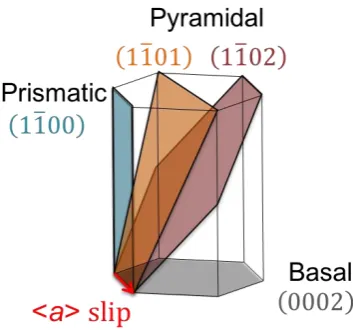
Perhaps the most studied of structural hcp metals is the group of α-Ti alloys. The loading orientation-dependent mechanical behaviour observed in the α-Ti alloy is likely to be applicable to the other HCP polycrystals as well [3]. In magnesium alloy, slip systems are limited, among which basal <a> slip is the primary slip system with the lowest critical resolved shear stress (CRSS), which represents the value of stress required for crystal slip on a given crystallographic plane [6]. Together with the other non-basal <a> slip systems (1 prismatic slip system and 2 pyramidal slip systems), there are only four independent slip systems (Fig. 1). This is clearly insufficient to accommodate the required five independent plastic strain components, particularly since none of the slip systems can lead to plastic deformation along the c-axis.
Figure 1. <a> slip systems
Furthermore, deformation twinning is an additional deformation mode that can accommodate inelastic tensile straining along the c-axis, with the (102) <101> tension twinning mode being the most commonly observed twinning. Owing to the polar nature of twinning that is not activated under compression along the c-axis, different response is expected for different grain groups during tensile-compressive loading [7][8]. The main purpose of this paper is to probe the strain evolution in a bent bar of wrought
[image:2.595.311.539.224.379.2]to the basal plane for c-group grains.
Figure 2. Schematic explanation of the orientation of a- and c- group grains
B. Severe Plastic Deformation
The Mg alloy used here was processed by a version of Severe Plastic Deformation referred to as Constrained Groove Pressing (CGP). The starting material was AZ31B alloy plate in the “O” (fully annealed) condition.
[image:2.595.69.246.472.637.2]accommodating the plastic strain and refining grain size. Dies can be heated up to a certain temperature and then before each pressing the sample is placed onto the dies and heating is allowed to occur over a period of time [9].
To prepare the sample studied here, the dies were heated to a set temperature at the beginning of each cycle and maintained for 5 minutes to allow homogenization. Each cycle involved constrained groove pressing and straightening pressing, and before each subsequent pressing the sample was placed between upper and lower dies to allow heating for 2 minutes, and removed immediately after the pressing allowing cooling down in the air. During pressing the crosshead speed was 5.2mm/s, corresponding to the initial strain rate of 2.3s-1 approximately. Die dimension of t=2mm was used. Four cycles of CGP were applied with the
temperature of 250˚C for the 1st cycle, 200˚C for the 2nd, and 150˚C for the 3rd and 4th cycles.
C. Bending Test
As shown in Fig. 4(a), the CGP processed sheet was cut along the cross-section, and a small bar with dimension of 23×1.8×2.1mm was obtained.
The cross-section has a periodic wavy shape resulting from incomplete straightening after CGP (referring to the right image in Fig. 4 (a)), with the period length of 8mm. A 5kN Deben (5kN Extended Tensile Tester, MT10223) was used to carry out 3-point bending test on the small bar with the loading force parallel to the normal direction and the centre roller in 3-point bending aligned with the trough of the periodic wave surface profile. The setup of 3-point bending is
a b
[image:3.595.58.557.59.317.2]c d e f
Figure 3. Schematic illustration of a constrained groove pressing circle: a. dimension of groove dies and setup of experiment. b. groove pressing. c. straightening pressing. d. 180º rotated sample. e. groove pressing after rotation. f. straightening pressing after rotation.
(a) (b)
[image:3.595.78.503.540.755.2]at Beamline I15, Diamond Light Source, UK. The energy of the X-ray beam was set to 72keV using monochromator, and approximately square beam with the size of 0.02 mm was used.
The sample was scanned across the monochromatic beam along the line indicated in the image on the right in Fig. 4(a) from B to A, with the step size of 0.01mm, corresponding to half of the beam size. Note that bending load was already removed during XRD experiment.
The d-spacing is related to the change of peak position on the diffraction pattern through Bragg’s Law [10]:
nλ=2dsinθ,
[image:4.595.62.274.432.641.2]where n=1,2,3,…, and λ is wavelength of the X-ray beam, d is the lattice spacing and θ is half the angle between the incident and reflected beam. This means that strain can be calculated by examining the change of peak position, which can be acquired by fitting the peak with a Gaussian or Lorentzian profile.
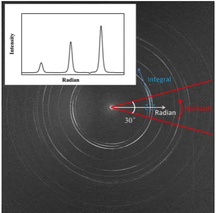
Figure 5. Caking of diffraction pattern
Fig. 5 illustrates how to perform ‘caking’ on a Debye-Scherrer ring pattern during data analysis. Obtaining intensity-radial plot needs the combination of radial binning and azimuthal integration. For caking with specific parameters, i.e. a caking angle and an orientation, it involves performing azimuthal integral within a radial bin within a sector defined by the caking parameters. An example where the caking angle is 30º and the orientation is 0º (parallel to x-axis) is shown by the red sector in Fig. 5. The orientation of
discussion, for convenience, the sample (bent beam) is divided into two parts according to the deformation status: the left side refers to the side where tensile plastic deformation took place, and compressive residual strain was accommodated (the side where the load was applied using two pins). The right hand side represents the other half of the beam, which is subjected to compressive plastic deformation during loading and is left with tensile residual strain after loading (the side where the load was applied through one pin).
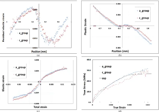
Fig. 6(a) indicates the residual elastic strains of each grain group along y-axis, obtained by comparing peak positions from XRD patterns to the theoretical lattice parameter values. Introducing strain along c-axis requires the activation of twinning, while for a-axis strain, slip is the principal deformation mode. On the tension side the two curves exhibit a fairly good agreement, indicating that the grains in these two groups experience little or no difference in plastic deformation when the sample is subjected to tensile loading. This means that slip and twinning demonstrate similar deformation behavior under tension. On the compression side however, noticeable asymmetry can be observed between the a- and c- group grains. For c-group grain, the asymmetry is due to the polar nature of twinning system that precludes plastic deformation under compression. Therefore, the most prominent difference in response is under compressive loading. This is consistent with the fact that twinning is only activated under tensile loading perpendicular to the basal plan or compressive loading parallel to the basal plan [11].
that has a projected component on the chosen direction, albeit smaller than in the a-group.
When calculating the total elastic strain during loading, the strains introduced by bending moment should be taken into consideration, which is linear throughout the beam. Fig. 6(c) demonstrates the plots of elastic strain vs total strain. Asymmetry of response can also be seen here. It can be seen that under compressive loading, these two groups are characterised by different ease of yielding: a-group grains exhibit easier yielding than c-group, which shows apparent hardening. This can be explained considering the ease of activation of slip and twinning in the system: slip is
activated more easily than twinning, therefore it is easier for a-group grains to yield. In other words, grains that experienced loading parallel to the basal plane are more readily deformed plastically compared with those whose c-axis is parallel to the loading direction.
In order to calculate the true stress along y-direction across the beam using plane-strain assumption, total x-direction strain should also be known. Residual strain for x-direction was obtained from XRD data, and the stress was calculated using the sum of residual strain and the strain introduced due to Poisson effect. Comparison between XRD results and the experimental stress-strain curve is given in Fig. 6(d). XRD results show satisfactory agreement with macroscopic tensile test results.
IV. CONCLUSION
By studying the residual elastic lattice strains introduced in a bending test, the asymmetry of tensile-compressive behaviour of c-group grains was revealed in Mg AZ31B alloy previously subjected to constrained groove pressing. It was demonstrated that the asymmetry of twinning under loading along the c results in efficient accommodation of tensile plastic strain, whilst this mechanism is inhibited under compression. This important distinction in the deformation mode affects the course of yielding, and determines the subsequent residual stresses. For each grain group, the ease of yielding depends on the activity of specific deformation modes due to slip or twinning, with grains deforming plastically most readily if the loading direction is parallel to the basal plane. The residual and ‘live’ stresses were calculated using the plane-strain assumption and were compared with the stress-strain curve from conventional macroscopic mechanical test, showing good agreement.
ACKNOWLEDGMENT
We would like to thank Dominik Daisenberger from Beamline I15 at Diamond Light Source, UK, for his support in scheduling and conducting the X-ray diffraction experiment. AMK acknowledges funding received for the
(a) (b)
(c) (d)
Figure 6. (a) Residual elastic strains after loading removal of a-group and c-groupacross the beam measured experimentally. (b) Plastic strains of a-group and c-groupalong the central scanning line of the sample obtained through linear fitting of residual elastic strains and subtraction. (c)Elastic strains vs total strains of
[image:5.595.50.558.51.410.2][4] Lunt, Alexander JG, et al. "A state-of-the-art review of micron-scale spatially resolved residual stress analysis by FIB-DIC ring-core milling and other techniques." The Journal of Strain Analysis for Engineering Design (2015): 0309324715596700.
[5] Zhang, Shu Yan. High energy white beam X-ray diffraction studies of strains in engineering materials and components. Diss. University of Oxford, 2008.
[6] Gong, Jicheng, et al. "< a> Prismatic, < a> basal, and< c+ a> slip strengths of commercially pure Zr by micro-cantilever tests." Acta Materialia 96 (2015): 249-257.
[7] Lee, Soo Yeol, Huamiao Wang, and Michael A. Gharghouri. "Twinning-Detwinning Behavior during Cyclic Deformation of Magnesium Alloy." Metals 5.2 (2015): 881-890.
[8] Kada, Sitarama Raju. Deformation of magnesium alloys during laboratory scale in-situ x-ray diffraction. No. Ph. D. Deakin University, 2013.
[9] Lee, J. W., and J. J. Park. "Numerical and experimental investigations of constrained groove pressing and rolling for grain refinement." Journal of Materials Processing Technology 130 (2002): 208-213. [10] Xie, Mengyin. X-ray and neutron diffraction analysis and fem
modelling of stress and texture evolution in cubic polycrystals. Diss. University of Oxford, 2014.
[11] Polmear, I. J. "Light alloys: metallurgy of the light alloys." Metallurgy and Materials Science, Arnold, Great Britain (1995): 232-233. [12] Golshan, Mina, et al. "Analysis of plastic deformation and residual