Abstract— Precise speed control is an important
requirement for efficient industrial automation. Direct current (DC) motors have been extensively used for this purpose. The conventional method employs analog circuits to control the speed of the DC motor by varying the voltage of the armature while the field voltage is kept constant. In this paper, a digital speed control of DC motor using pulse width modulation technique was implemented by replacing analog circuit with an Atmel AT89S52 microcontroller circuit. An experimentation of the design showed that the DC motor can run forward motoring, forward regeneration, reverse motoring and reverse regeneration. This digital approach proved to have increased precision and greater control efficiency. Thus, a centralized control of several motors can also be achieved.
Index Terms—DC motor speed control, microcontroller,
pulse width modulation, quadrant choppers
I. INTRODUCTION
UTOMATION of industrial processes offers the benefits
of better quality, increased production and control, and decreased costs. Several industrial automation processes utilize electric motors for control functionalities. This requires the electric motor to operate at different speeds and in different modes. High starting torque and controllability of Direct Current (DC) motors has led to their wide range usage in industrial processes that require accurate and precise speed control.
DC shunt motors are considered appropriate for most industrial control due to their advantageous features. They operate at approximately constant speeds. For the same current input, the starting torques is not as high as in series motors. To maintain an approximately constant speed from no-load to full-load, the shunt regulator enables the required speed control easily and economically. DC shunt motors have wide range of applications which include driving constant speed line shaft loads, lathes, centrifugal pumps, machine tools, blowers and fans, and reciprocating pumps [1]. They achieve higher accuracy, greater reliability, quick response, and higher efficiency since there are no I2R losses. A full four-quadrant control is possible to meet precise high-speed requirement [2].
Manuscript received February 23, 2017; revised March 28, 2017.
A. U. Adoghe, S. O. Aliu, S. I. Popoola, and AAA. Atayero,
Department of Electrical and Information Engineering, Covenant University, Ota, Nigeria.
{anthony.adoghe, atayero} @covenantuniversity.edu.ng, segunpopoola15@gmail.com
Over the years, various DC shunt motor speed control techniques have been employed. In flux control approach, the motor speed increases as the rate of flux decreases. The rate of flux changes when the shunt current is varied using a shunt field rheostat. Since the shunt current is relatively small, the shunt field rheostat has to carry only a small current which results in low I2R loss, such rheostat is small in size. This method is therefore very efficient [3].
The rheostat control method is suitable when speeds below the no-load speed are required. With a constant supply voltage, the voltage across the armature is varied by inserting a variable rheostat in series with the armature circuit. For a constant load torque, the speed is approximately proportional to the potential difference across the armature [3]. However, this technique is inefficient, expensive, and not suitable for rapidly changing loads. For better improvement, a diverter can be connected across the armature in addition to the armature control resistance. The voltage control method may be multiple voltage control or Ward-Leonard system. In multiple voltage control, the shunt field is permanently connected to a fixed exciting voltage but the armature is supplied with different voltages. This is achieved by connecting the armature across one of the several different voltages by means of suitable gear. The intermediate speeds can be obtained by adjusting the shunt field regulator. However, this method is not frequently used. The Ward-Leonard method is used where an unusually wide and very sensitive speed control is required. However, its overall efficiency is low at light loads [3].
Prior to the advent of power electronics and microcontrollers, it has been very difficult to realize variable speed of DC motors in any application. Today, solid-state electronic devices have become a better choice for DC motor speed control [11]. These devices control the motor speed by adjusting either the voltage applied to the motor armature, the field current, orboth [6]. Unipolar pulse width modulation is suitable for cases where the reversal of motor direction is not required. A bidirectional DC motor speed control can be achieved using the H-bridge integrated circuits controlled by a microcontroller [7].
In this paper, we design and implemented the digital speed control of DC motor using pulse width modulation technique. The analog circuit was replaced with an Atmel AT89S52 microcontroller circuit. Similar to the traditional approach, the field voltage was kept constant while the armature voltage was varied. The switching action was done by four-quadrant choppers which utilized Metal–Oxide Semiconductor Field-Effect Transistors (MOSFETs). The
Digital Speed Control of DC Motor for
Industrial Automation using Pulse Width
Modulation Technique
Anthony U. Adoghe, Simisola O. Aliu, Segun I. Popoola, Aderemi A. Atayero,
Members, IAENG
motor was connected to the Optoisolator-MOSFET circuitry. Optoisolators accepted the input signals from the microcontroller and provide instructions to the integrated circuit that controls the MOSFETs. The Microcontroller is connected and programmed to work with a Liquid Crystal Display (LCD) unit and a keypad.
The remainder of this work is organized as follows: Section II gives the materials and explains the methods employed; Section III presents the system implementation and testing procedures; Section IV discussed and summarized the results obtained.
II. MATERIALS AND METHODS
Correct design specification is required for efficient system performance. The design parameters considered include input voltage, output voltage, maximum current, frequency of operation, voltage control steps, and direction of rotation. The DC motor controller operates at 6 V/12 V with a maximum current capacity of 5 A. The system operates at a frequency of 50 Hz. The input AC voltage is within the range of 150–270 V. A digital display is required to show the exact value of the input and the output voltages. Also, the current speed and direction of rotation should be displayed. Switches control the desired voltages (6 V/12 V/ 24 V), the speed range from 1 to 100 in steps of 1 and 5. The direction can be either clockwise or anticlockwise.
[image:2.595.56.282.441.574.2] [image:2.595.48.291.738.782.2]The complete system consists of six (6) different units. This include the power supply unit, the microcontroller unit, optoisolator unit, the LCD display unit, the MOSFET chopper unit, and the DC motor. This block diagram in Figure 1 shows the interconnections of the various units.
Figure 1: Block Diagram of the System
A. The Power Supply Unit
The power supply is made up of the transformer, the rectifier circuit, the filter circuit, and the regulator circuit. The circuit arrangement is shown in Figure 2. Two transformers are used to step down the AC voltage of 230 V to 15 V. The diodes converts the input AC current into DC. This is known as rectification. The rectified output is a rippled DC which requires filtering. The ripples are filtered using a capacitor arrangement. A positive voltage regulator is used to control the output DC voltage.
Figure 2: Block Diagram of Power Supply Unit
Three different power supplies were used to supply appropriate operating voltage to the microcontroller unit and two DC motors respectively. A series connection of two center-tap step down transformers of 15 V output voltage each fives a total power rating of 30 V, 5 A. The 30 V output of the transformer was fed into the bridge rectifier circuit. The diodes employed in the rectifier circuit have a forward bias of 0.7V each. A 12 V zener diode and 7805 voltage regulator IC control the DC output of the filter circuit. The output voltage of the regulator circuit is 5 V that is required for the operation of the microcontroller unit [13].
B. The Microcontroller Unit
A microcontroller is made up of a powerful processing unit integrated with memory, and various input and output interfaces, all on a single chip. The use of a microcontroller reduced the size of the Printed Circuit Board (PCB) and the cost of design.
The programmable microcontroller used in this work is AT8952. The choice of this microcontroller is due its small size and cheap price. It has a 4 KB of in-system programmable flash memory, 1000 write/erase cycles, 128 x 8-bit internal Read Only Memory (RAM), two 16-bit timer/counters, and six interrupt sources. It is also equipped with full duplex UART serial channel, low-power idle and power-down modes, watchdog timer, and dual data pointer [10]. In addition, AT8952 has a high speed of program execution and high processing capability. The interface and the memory was adequate for the task at hand since it has to learn only 35 single word instructions. The above-mentioned requirements facilitate the choice of the AT8952 chip.
All the instructions for control functions are programmed into the microcontroller. The 5 V DC output of the power supply is connected to pin 40 of the microcontroller. The microcontroller uses a pull down resistor connected to port 0, and a crystal oscillator of 11.0592 MHz in conjunction with a couple of capacitors of 27 µF. The resistor and the crystal oscillator were connected to pins 18 and 19 of the microcontroller for stable oscillation as shown in Figure 3.
C. The LCD Display Unit
The unit is responsible for the digital display of output information. The LCD was properly interfaced to the microcontroller as sown in Figure 4. The data pins of the LCD were connected to port 2 of the microcontroller.
D. The Keypad Unit
R25 1k +5V
L C D
C14 27pF A atmel8952 D 3 D4 D2 D1 D 7 D 0 D6 D 5 P 1 .0 P 1 .1 P 1 .2 P 1 .3 P 1 .4 P 1 .5 XTAL1 XTAL2 P 0 .6 P 0 .4 P 2 .0 P 2 .1 P 2 .2 P 2 .3 P 2 .4 P 2 .5 P 2 .6 P 2 .7 P 3 .0 P 3 .1 P0.0 +5V X2 16MHz
C12 27pF 9 39 10 11 36 21 22 26 27 28 25 2 3
40 6 54 1
23 24 18 19 35 31 20 1 2 3 4 5
8 7 6
10 9 15 R/W VO E R S K VCC GND 13 14 12 11
V D D reser V D D V SS 180R 16 P0.1 10k C 5 1 0 µ F P 1 .7 P 1 .6 87 + 1 -1 + 5 -5 c lk an ti c lk 0 n /o ff v o lt s 1 ,0 0 0 µ F +5V 7805 1N4007 12V Transformer AC 240V 1N4007 Power supply 1 ,0 0 0 µ F P0.2 38 37 560R 560R 560R 560R 560R 560R a c b P 0 .5 P 0 .3 33 34 560R 560R 560R 560R 560R 560R 560R 560R g f e d
[image:3.595.62.270.47.511.2]Figure 3: The Microcontroller Unit
[image:3.595.350.501.469.747.2]Figure 4: Interfacing LCD with the Microcontroller
Figure 5: The Keypad Unit
A. The DC Motor
The DC motor is the output device that is varied by the control switches. The speed of the DC motor is directly proportional to the armature voltage and inversely proportional to the flux. By maintaining a constant flux and varying the armature voltage, the speed of the motor is varied.
B. The Optoisolator Unit
The optoisolator was used to transmit signals or data across an electrical barrier using a beam of light, and it achieved an excellent isolation [12]. In this work, they were used in the transfer of on-off control signals for switching purposes and for circuit isolation. The second pins of all the optoisolators were interconnected while the first pins were connected to resistors. Interchanging the positions of the pins and the optoisolators changes the direction of rotation of the DC motor. The optoisolator supplied an input to the microcontroller. The microcontroller processes the information and display the appropriate output on the LCD display unit.
C. The MOSFET Chopper Unit
A chopper is a DC to DC converter with a variable DC voltage [9]. The MOSFETs acted as switches as shown in Figure 6. They are employed to switch on and off the power supply to the load for a certain time interval. This was achieved by varying the firing angle. By so doing, the speed of the DC motor was controlled.
D. Software
Keil µVision3 software, Express PCB, and Express SCH were used for the programming, the layout design, and the schematic design respectively. µVision3 is an Integrated Development Environment (IDE) for code writing, compilations, and debugging [14]. It comprised of a project manager, a make facility, tool configuration, an editor, and a debugger. Express PCB V5.6.0 and Express SCH V5.6.0 were used in this work. The codes were written in assembly language. This language was preferred to a high-level programming language because of speed, control, and preference. The programs run faster since there is no need for compilation of source codes. The programmer interacts with the embedded system hardware directly.
bc548 bc558 10k 10k 1 2 v 1 0 0 u f irf150 1k bc548 bc558 10k 10k 1 2 v 1 0 0 u f irf150 1k bc548 bc558 10k 10k 1 2 v 1 0 0 u f irf150 1k bc548 bc558 10k 10k 1 2 v 1 0 0 u f irf150 1k Vcc(6-24v) gnd(6-24v) Motor a vcc1 gnd1 Vcc unregulated (6-24v) Motor b gnd(6-24v) Vcc unregulated (6-24v) vcc2 gnd2 Vcc(6-24v) a c b d
[image:3.595.81.259.521.662.2]III. SYSTEM IMPLEMENTATION AND TESTING
The complete circuit was initially arranged on a bread board and stage by stage testing was performed before it was finally implemented on a PCB board. Thereafter, the various components that made up the circuit of each unit of the system were soldered in tandem to meet desired workability.
Three voltage levels were achieved using the DC motor controller. They are 6 V, 12 V, and 24 V with a maximum current capacity of 5 A. The 12 V and 5 V outputs were supplied to the switching circuit and the control circuit respectively. In addition to the traditional power supply circuit, a circuit called Switched Mode Power Supply (SMPS) was used for efficient, secured voltage supply to the microcontroller, eliminating possible fluctuations. This was used to supply voltage to the various stages of the circuit during the breadboard test. During the soldering phase, the power supply was still used to test various stages before they were finally soldered.
[image:4.595.307.550.182.320.2]The main component in the control circuit is the microcontroller, AT8952. The microcontroller was programmed before physical implementation on the PCB board. The ASM compiler used for debugging was the mikrolingual complier.
Figure 7: Interconnections of the Power Supply Unit and the Control Unit
Other component parts of the control circuit include current limiting resistors, filtering capacitors, rectification diodes, crystal oscillators and voltage regulators as shown in Figure 7. The switching circuit comprised of MOSFETs. The arrangement of the optoisolators, zener diodes, transistors, resistors, filtering capacitors, power buffers (TIP41C) transistors was to amplify the current to a required level needed to drive the MOSFETs and voltage regulators.
The LCD was connected to the system so as to monitor and display the speed of the motor, the direction of the motor (clockwise or anticlockwise) and its output voltage (6V, 12V or 24V). The NHD-0216K1Z-NSW-BBW-L model was selected because of the following features: new haven display; 2 lines by 16 characters; version line; side white LED; and low power [8].
At the final stage, all the circuit components were carefully soldered on a PCB. The PCB was used instead of veroboard because of its higher efficiency with little or no short circuit between current paths. Also, the choice of PCB made the circuit design compact, and ensured neatness by eliminating the need for connecting wires. A local, cost-effective copper etching technique was used. The circuit
design were done using Express PCB software as shown in Figure 9. Hard copies were printed and pasted on copper clads. Heat generated by electric iron was used to transfer the circuit diagram pattern to the copper clad surface. The uncovered portions of the copper clad were etched in Iron Chloride. The appropriate components were carefully placed in drilled holes for onward soldering. The electrical components were soldered to form a complete circuit as designed shown in Figure 8.
[image:4.595.307.548.349.451.2]Figure 8: Complete System Circuitry
Figure 9: PCB Layouts of the Control Circuit
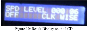
[image:4.595.59.281.365.498.2]The circuits were separately tested to ensure that the correct input and output values were obtained. This was done using a multimeter. DC motors were tested with input voltages of 6, 12, and 24 V. Keys assigned to different functions were tested and the information such as the supply voltage, speed of rotation, and direction of rotation was monitored as displayed on the LCD as shown in Figure 10.
Figure 10: Result Display on the LCD
[image:4.595.333.520.584.650.2]Figure 11: The External Outlook of the System
IV. CONCLUSION
This work achieved a design and implementation of a DC motor speed control for operating voltages of 6 V, 12 V, and 24 V with a maximum current capacity of 5 A. The control mechanism enables efficient speed regulation with more reliable functionalities even at large currents. The analog circuit was replaced with an Atmel AT89S52 microcontroller circuit. Similar to the traditional approach, the field voltage was kept constant while the armature voltage was varied. The switching action was done by four-quadrant choppers which utilized Metal–Oxide Semiconductor Field-Effect Transistors (MOSFETs). The operating characteristics of the motor can be altered using the keypad. The DC motor operates in four operation modes: forward generating; forward motoring; reverse generating; and reversed motoring. The control information is displayed via the LCD unit.
However, the application of four-quadrant chopper control is limited to DC motors whereas AC motors have extensive applications in industrial automation. Therefore, future work should be done to achieve digital speed control of AC motors.
REFERENCES
[1] Thomas E. Kissell, “Industrial Electronics”, 2nd Edition Prentice
Hall , 2000.
[2] Irvin M. Gottlieb, “Electric Motor and Control Techniques”, Jameco,
2nd Edition, Chapter 2, pp. 32-54.
[3] B.L. Theraja and A. K.Theraja, “A Textbook of Electrical
Technology”, S. Chand, 22nd Edition, 2005, Vol. 2, Chapters 29-30,
pp. 996-1078.
[4] P.S. Bimbra, “ Power Electronics”, Delhi, Khanna Publishers, 2007.
[5] Motor Drives. Available online: http://www.ee.ttu.edu/motordrives
[6] New Haven Display, “NHD-0216K1Z-NSW-BBW-LLCM (Liquid
Crystal Display Module) Datasheet”, 2008. Available at www.newhavendisplay.com/specs/NHD-0216K1Z-NSW-BBW-L.pdf
[7] Stephen W. Fardo et al, “Electrical Power Systems Technology”,
CRC Press, 3rd Edition, 2008, Chapter 14, pp. 349-399.
[8] John Bird, “Electrical and Electronic Principles and Technology”,
Newnes, 2nd Edition, 2003, Chapter 22, pp.. 328-350.
[9] A. Morbid, S.B. Dewan, “Selection of commutation circuits for four
quadrant choppers”, In Proc. International Journal of Electronics’03, 1988, pp. 507-520.
[10] M. A. Mazidi, J. G. Mazidi and R.D. McKinlay, “The 8051
Microcontroller and Embedded Systems- using Assembly and C”. Delhi: Pearson Prentice Hall, 2009.
[11] M.D. Singh and K.B. Kanchandani, “Power Electronics”, Tata
McGraw Hill, 2008.
[12] Texas Instruments, “MCT2, MCT2E Optoisolators SOES023
datasheet”, Mar 1983 [Revised Oct 1995]
[13] Fairchild Semiconductor, “3 Terminal 1A Positive Voltage Regulator:
KA78XX/KA78XXA datasheet”, 2003.
[14] ATMEL, “8 bit Microcontroller with 8K Bytes in system