Interpolator: A Two-dimensional Graphical Interpolation
System for the Simultaneous Control of Digital Signal
Processing Parameters
*Martin Spain and Richard Polfreman
Music Department
Faculty of Engineering and Information Sciences,
University of Hertfordshire, College Lane, Hatfield, Herts. AL10 9AB. [email protected], [email protected]
Abstract
The musical use of real-time digital audio tools implies the need for simultaneous control of a large number of parameters to achieve the desired sonic results. Often it is also necessary to be able to navigate between certain parameter configurations in an easy and intuitive way, rather than to precisely define the evolution of the values for each parameter. Graphical interpolation systems (GIS) provide this level of control by linking multiple parameters to cursor movements within a visual control space. This paper describes Interpolator, a two-dimensional interpolation system for controlling Digital Signal Processing (DSP) parameters in real time.
1 Introduction
There are several graphical interpolators already available for controlling DSP parameters, perhaps the most widely known of which is Arboretum’s Hyperprism™ software. Hyperprism comprises a collection of digital effects with a graphical user interface that allows parameter changes to be made in real time by horizontal and vertical mouse movement in a control space. However, Hyperprism does not strictly perform interpolation between the maximum and minimum values for each parameter, instead simply incrementing or decrementing the parameter depending on the cursor’s position in the space. In other graphical interpolators a
gravitational style model is used, where individual sets of parameter values are represented by planets whose sizes indicate their level of influence. Several such planets are placed in a two-dimensional space and a cursor moved around in the space to produce a smoothly varying series of parameter values. These values are interpolated from the settings of each planet. Typically the influence of a planet on the cursor’s position obeys an inverse square rule according to the distance from the cursor to the centre of a planet, although this may be variable in some interpolators.
The gravitational model of interpolation can present some limitations. The field of influence of each object, represented by the gravitational pull of each planet, is invisible and therefore accurate navigation through the interpolation space can be difficult. The principal source of feedback to the user is through the sound itself with limited indication of how the relative influences of each planet are currently weighted. Whilst the sonic feedback is the most important factor, having a clear graphical indication can aid in precise performance control. The planets also exert their influence omnidirectionally, with no way of directing the influence of each planet over a specific area.
2 The Light Model of Interpolation
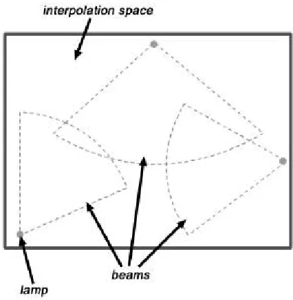
Interpolator builds upon conventional interpolation paradigms by introducing a light model of interpolation. This allows a more flexible control space by representing groups of parameter settings as lamps whose beams indicate their area of influence. This introduces several potential advantages over previous interpolation systems. Unlike a gravitational interpolation model where the area of influence is invisible, in the light model of interpolation the influence of each lamp is clearly visible to the user. The lamps have a variable angle, aperture and
[image:2.595.190.403.234.452.2]extent, so the beam of influence can be directed very precisely within the interpolation space (Figure 1).
Figure 1: The light model of interpolation.
These features give the lamps the ability to have very narrow or very open influence areas. Since the size of the beam now represents the influence area, the lamps themselves do not take up much space in the interpolation area, unlike the variably sized planets usually used in a gravitational model. The light model still allows the emulation of a gravitational model by using lamps with 360-degree apertures. The user can define up to four parameter sets, represented by four beam colours, and each lamp represents a set of values for the parameters assigned to the lamp’s beam colour. This allows concurrent interpolation of independent processing factors. The lamps can be thought of as individual ‘sound states’, and the user navigates between these states to find new sound states.
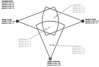
parameter that is being controlled by every beam colour, allowing interpolation to take place between the values associated with each lamp, and the values associated with the background. In this manner the background acts as an omnipresent lamp of all four colours. When non-active, interpolation will only take place when two or more beams of the same colour overlap, replicating the behaviour of Syter and similar gravitational interpolators (although Interpolator’s ‘planets’ have no influence outside their extent, whereas gravitational ones typically extend throughout the interpolation space).
Figure 2: Lamps with assigned parameters.
Figure 2 shows an example layout of lamps in diagrammatical form, two with ‘red’ beams and one with a ‘green’ beam. The red lamps both control the same two parameters. The green lamp controls two different parameters. Values are assigned to the parameters controlled by each lamp, and the background holds values for all parameters that are being controlled. The two red lamps each hold different values for the same two parameters that they control. When the cursor is moved around the interpolation space, values for each parameter are calculated depending on the location of the mouse in relation to each lamp (three example positions are shown in the figure). The influence of the lamps decreases the further the cursor position is from the centre of each lamp. If the cursor moves outside the beam of a lamp altogether, that lamp has no influence on the cursor position and the parameters that lamp controls are set to the background values.
3 GRM Tools
host application to allow Interpolator to communicate with the GRM Tools plugins. The plugins themselves exist in VST format, and are launched either from within a VST-compatible audio application or from the GRM Tools host application. Many of the GRM Tools plugins have a significant number of parameters, of which only one or two can be controlled in real time using the existing interface. This made it a suitable system with which to evaluate the light model of interpolation.
Figure 3: The GRM Tools Bandpass plugin.
4 Interpolator
4.1 User Interface
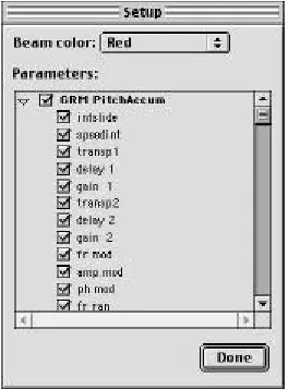
Interpolator currently functions as a standalone application that runs on Mac OS computers (Mac OS 8.1–9.x) alongside the GRM Tools host application, communicating with the plugins by means of a shared library. Interpolator has two main modes of operation: Edit mode and Performance mode. Edit mode is where the configuration of the interpolation space takes place. Whilst in Edit mode, the user can configure the parameter assignments to each beam colour by checking the appropriate box in the Colour Setup dialog. Figure 4 shows the dialog, with parameters from the GRM Tools PitchAccum plugin assigned to the red beam colour.
[image:4.595.232.364.546.725.2]Edit mode also allows the user to place lamps onto the interpolation space and adjust their position, angle, aperture and extent, and to assign values to each lamp’s set of parameters and to the background. These values can either be specified manually, or the user can request the current values for the parameters from the appropriate GRM Tools plugins. Figure 5 shows a Lamp Setup dialog, with values assigned to the parameters controlled by the red beam colour.
Figure 5: Lamp Setup dialog.
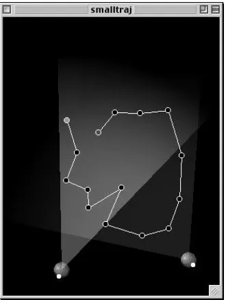
Performance mode is where the interpolation takes place. In order to perform interpolation, the user can drag the mouse around the interpolation space in a ‘freehand’ fashion. Alternatively, Interpolator allows the user to define a trajectory through the interpolation space for a cursor to follow. The trajectory is a series of points connected by straight lines, and a set of playback controls in the toolbar allows playback of the cursor along the trajectory. Figure 6 shows a trajectory displayed in the interpolation space.
Figure 6: A trajectory shown in the interpolation space.
[image:5.595.216.381.454.673.2]4.2 The Interpolation Engine
The interpolation engine acts as the core of Interpolator. It is only active in Performance mode, and performs all the calculations necessary to control the correct parameters in the appropriate GRM Tools plugin, based on the position of the mouse or playback cursor in the interpolation space. For a given position in the interpolation space, the interpolation engine calculates whether or not the position is within any of the beams. If the position is within one or more beams, the interpolation engine determines the distance from each lamp to the current position. Once the distance from the centre of the lamp has been calculated, the weight of that lamp is calculated.
The weight of a lamp can be considered as a measure of the lamp’s influence on the cursor position for that lamp’s beam colour. The weight of a lamp is dependant upon the distance from the centre of the lamp to the cursor position, the extent of the lamp’s beam and the current influence curve settings, and is measured as a percentage. If the background is active, the interpolation engine also calculates the background weight for each of the four lamp colours. The background weight completes the percentage total for every lamp weight for the current colour. For example, if all lamps with red beams have a total combined weight of 70%, the background makes up the remaining 30%. However, should there be more than one red beam overlapping at the cursor position the total influence for the lamps may reach 100% or more. In this case the background will have no weight and therefore no effect on the cursor position – the background has been ‘washed out’ by the total intensity of the beams at this point.
Once the total weights for the beam colours and the background weight have been calculated, the result values for every parameter that is being controlled are calculated. The weighted values from the lamps and the background are summed and then divided by the total weight in order to give each interpolated value which is then sent to the appropriate GRM Tools plugin.
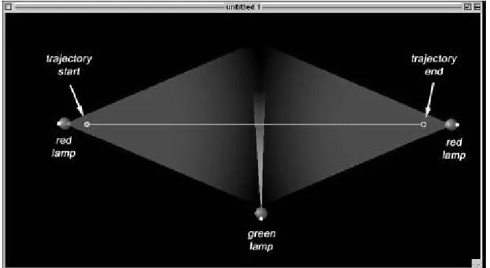
[image:6.595.119.477.543.739.2]4.3 Example Interpolation Layout
Figure 7 below shows an example Interpolator document, consisting of two red lamps and one green lamp.
The red lamps both control the same plugin parameters but with different values associated with each lamp. A third lamp with a green beam arranged at the mid-point between the two red lamps controls parameters from a different plugin, with a very small aperture. A straight line trajectory is drawn between the two red lamps and as the cursor is played back along the trajectory, the resulting sound will gradually ‘morph’ between the two sound states represented by the red lamps, and in the middle of the interpolation the green lamp will suddenly and briefly have an effect on the interpolation. This kind of interpolation would be difficult to achieve with previous systems.
5 Conclusions and Further Research
Interpolator has been subject to substantial testing and user evaluation both throughout the development cycle and once a functioning prototype was achieved. The response from the user evaluations has been positive, with all users who took part in the testing process finding the light model of interpolation a successful progression for interpolation systems and Interpolator to be a useful tool for controlling GRM Tools. All users who took part in the evaluation process also stated that they found the light model of interpolation a more useful system than the gravitational model.
Interpolator is a prototype system, designed to evaluate the light model of interpolation, and as it stands has several limitations.
• The method of operation is too modal with many mouse clicks needed to achieve certain functions, and this can make locating the correct mode to perform a task somewhat difficult.
• The user-interface is functional, but it would be desirable to add some additional features such as a set of ‘remote’ playback controls for controlling GRM Tools’ sound playback from within Performance mode.
• Interpolator currently requires a very fast computer in order to draw the beams quickly and allow easy editing of beam settings without waiting for screen redraws (despite using various optimisation techniques, to speed up drawing further would require a large amount of RAM).
In conclusion, it is believed that Interpolator is a successful progression for interpolation systems. The light model of interpolation offers a far greater degree of visualisation when performing interpolation tasks than previous systems, which allows navigation through the interpolation space to be performed much more accurately. The concept of using lamps and beams to represent a number of ‘sound states’ within the interpolation space also provides an intuitive method for users looking to create new sounds without having to spend a large amount of time adjusting DSP parameters individually.
situation, controlling multiple image processing parameters from graphics plugins in real time to effect changes to a graphics file. Typically the user interface for image processing plugins only allows the user to change one parameter at a time, and so the ability to control any or all of the parameters for a plugin or even more than one plugin at once might yield visual results that might not have been discovered conventionally. Image processing plugins do not currently work in real-time, but some update the graphics file quickly enough to make this method of working feasible. Interpolator’s trajectory feature might not be useful when working in this manner, but perhaps would be more suited to working with 3-dimensional modelling software, where it could be used to create ‘morphs’ between lamps representing shape states.
Notes
* We would like to thank Emmanuel Favreau and Daniel Teruggi at INA/GRM for their advice and guidance, and for allowing the use and modification of their software for this project.
References
Adobe Systems Inc. 1998. Adobe Photoshop 5.0 User Guide. Adobe Systems Inc.
Favreau, E. 1998. Les outils de traitement GRM Tools. In Journées d’Informatique Musicale 1998(E4.1-E4.4). Marseille: CNRS-LMA.