~Solbourne
Computer
SE Quick Reference Guide
Sol bourne Confidential - Do Not Reproduce
Solboume Computer, Inc.
1900 Pike Road
Longmont, Colorado 80501
303-772-3400
Preface
This reference is intended as an abbreviated lookup resource for Solbourne field technical personnel. The information it contains is intended to cover a wide spectrum of reference material for the new as well as seasoned veteran. As you use it, please make notes in the blank Field Notes pages at the end of the book.
Please email [email protected].
Comments will be forwarded to everyone on the Uses' alias as well as archived for use in creating future editions to this guide. Especially note the sections in the guide that you use the least as well as those used the most. Apathy in this regard is aloud vote to make this the last edition.
The manual is divided into 15 sections, as follows:
Section 1 -System Configurations
This section provides system configuration information for the Solbourne product line.
Section 2 - Hardware Overview
The hardware characteristics of the Solboume product family are discussed in this section.
Section 3 - Peripherals: Disk and Tape Drives and Boards
Information on all peripheralS shipped by Solboume is given in this section.
Section 4 - Environmental Data
This section gives all the environmental information associated with the Solboume product family.
Section 5 - Boot Environment
A quick reference on the booting procedures is given in this section.
Section 6 - Man Pages on Key System Administration Files
Some of the most frequently used system administration man pages are given in this section.
Section 7 - Man Pages on Network Status Tools
This section offers frequently used networking man pages.
Section 8 - YP Services
This section gives information on setting and administrating YP.
Section 9 - Miscellaneous and 'How To .. : Information
Considerable miscellaneous information is given in this section.
Section 10 - General Diagnostics Information
This section introduces diagnostics and tells how to use the LEOs on the System and CPU boards.
Section 11 - System Power-On Self-Tests
The system power-on self-tests for the Series4 and SeriesS are given in this section.
Section 12 - dg Diagnostics
This section gives ~n overview of the standalone test controller (dg) diagnostics.
Section 13 -rdg Diagnostics
An overview of the ROM Resident Diagnostics (reIg) is given in this section.
Section 14 - mdg Diagnostics
The multiprocessing diagnostics (mdg) is covered in this section.
Section 15 -Field Notes
This section offers space for making notes.
Table of Contents
Section 1: System Configurations ... '" 1-1 1.1 Introduction ... 1-1 1.2 Series4 and Series5 / 600 ... 1-1 1.2.1 PCB Loading ... 1-1 1.2.2 Peripherals Loading ... 1-1 1.3 Model 820 ... 1-2 1.4 Series 4 and SeriesS/Soo ... 1-3 1.4.1 Peripherals Rules ... 1-3 1.5 Model 810 ... 1-4
Section 2: Hardware ... 2-1 2.1 Introduction ... 2-1 2.2 Kbus Backplane ... 2-1 2.3 System Board ... 2-2 2.3.1 System Board Revision Levels ... 2-4 2.4 Series 4 CPU Board ... 2-7 2.5 Series 5 CPU Board ... 2-8 2.6 CG 40 and CG30 Color Frame Buffer Boards ... 2-9 2.7 Memory Boards ... 2-10 2.8 VMEbus backplane ... 2-10 2.9 SCSI ... 2-11 2.10 Field Notes ... 2-12
Section 3: Peripherals: Disk Drives, Tape Drives, and Controllers ... 3-1 3.1 Introduction ... : ... 3-1 3.2 Maxtor LXT-2oo 200 Mbyte Hard Disk ... 3-2 3.2.1 LXT-2oo format.dat ... 3-3 3.3 Maxtor XT -43805 SCSI 5 Yo-inch FuJI Height 327 Mbyte Disk ... 3-4 3.3.1 XT-43805 format.dat ... 3-5 3.4 Maxtor XT-8760S SCSI S Yo-inch Full Height 661 Mbyte Disk ... 3-6 3.4.1 XT-8760S format.dat ... 3-7 3.5 Hitachi DKS14C-38 SCSI S Yo-Inch FuJI-height 327 Mbyte Disk ... 3-8 3.5.1 DK514C-38 format.dat ... 3-9 3.6 Hitachi DK515C-78C SCSI 5 Yo-Inch Full-height 661 Mbyte Disk ... 3-10
3.6.1 DKS15C-78C format.dat ... 3-11 3.7 Fujitsu M2382K SMD 8-inch 830 Mbyte Disk ... 3-12 3.7.1 M2382K format.dat ... 3-13 3.8 Seagate Sabre 9720-1230 SMD8-inchOne Gbyte Disk ... 3-14 3.8.1 Sabre 9720-1230 format.dat ... 3-15 3.9 Archive 20605 QIC-24 and 21505 QIC-150 Half-height, Yo-Inch Tape Drive ... 3-16 3.10 Exabyte EXB-82oo SCSI 5 Yo-Inch fuJI height 8 mm Cartridge Tape ... 3-17 3.11 H-P 88780B SCSI Yo-Inch Reel Tape Drive ... 3-18 3.11.1 Changing the 887SOB's SCSI Address ... 3-18 3.12 Xylogics 753 Controller Board ... 3-19 3.13 VMEbus/16 Line Multiplexer ... 3-20 3.14 Interphase Eagle 4207 Ethernet Board ... 3-22
Section 4: Environmental Data ... 4-1 4.1 Power Ratings, BTU Ratings, and Amperage Requirements ... 4-1 4.2 Operating Temperature ... :... 4-2 4.3 All Disk Drives: Special Handling for Temperature Changes ... 4-2. 4.4 Operating Humidity ... 4-2 45 Regulation Certification ... 4-2 4.6 Field Notes ... 4-2
Section 5: Boot Enviromnent ... A . . . :.;,~ . . 5-1 5.1 EAROM Enviromnent Variables .... "... -1 5.2 BOOT ROM Command List ... S 53 Boot Command Options ... 5-2 . 5.4 Booting from Specific Devices ... 5-2 5.5 Device_name/ProtocoCname Abbreviations ... 5-3 5.6 BOOT ROM Versions 3.2c (Series4) and 33 (Series5) ... 5-3 5.7 lnit daemon and System Initialization Scripts ... :... 5-3 5.8 Field Notes ... 5-4
Section 6: Man Pages on Key System Administration FUes ... 6-1 6.1 Introduction ... 6-1 6.2 ethers (5) ... 6-2 63 exports (5) ... 6-3 6.4 fstab (5) ... 6-5 65 group (5) ... " ... 6-7 6.6 hosts (5) ... ~.;:;; ... 6-9 6.7 hosts.equiv (5) ... ~... 6-10 6.B inetd.com(5) ... 6-12 6.9 networks(5) ... 6-13 6.10 netgroup(5) ... 6-14
~:~~ ~=::~~).:::::::::::::::::::::::::::::::::::::::::::::::::::::::::::::::::::::::::::::::::::::::::::::::::::::::::::::::::::::::::::::::::::: t~~
6.13 rpc (5) ... 6-20 6.14 services (5) ... 6-21 6.15 termcap(5) ... 6-22 6.16 ttytab (5) ... 6-24Section 7: Man Pages on Network Status Tools ... 7-1 7.1 Introduction ... 7-1 7.2 config (B) ... 7-2 7.3 df(1) ... 7-3 7.4 dkinfo(B) ... 7-4 75 du(1v) ... 7-5 7.6 format(Bs) ... 7-6 7.7 fsck (B) ... 7-7 7.8 mount(B) ... 7-9 7.9 ncheck(B) ... 7-13 7.10 newfs(B) ... 7-14 7.11 ps(1) ... 7-16 7.12 pstat(B) ... 7-20 7.13 savecore (8) ... 7-24 7.14 vmstat(B) ... 7-25 7.15 iostat (B) ... 7-27
7.16 uustat (Ie) ... 7-28 7.17 etherfind (8c) ... , ... 7-30 7.18 nfsstat (8e) ... 7-32 7.19 showmount(8) ... , ... 7-33 7.20 trpt (Sc) ... 7-34 7.21 netstat(Sc) ... 7-3S
Section 8: yP Services ... 8-1 8.1 Commands Used for Maintaining yP ... 8-1 8.2 How Administrative Files Are Consulted on a yP Network ... 8-2 8.3 How to Set up a Master yP Server ... 8-3 8.4 Altering a yP Client's Files To Use yP Services ... 8-3 8.5 How To Set Up a Slave YP Server ... 8-5 8.6 How To Set Up a YP Client ... 8-6 8.7 Reference Infonnation on Troubleshooting yP ... 8-6
Section 9: Miscellaneous and 'How To .. .' Infonnation ... 9-1 9.1 Setting the Correct Timezones ... 9-1 9.% Extending Swap Space with a File Using swapon ... 9-1 9.3 Setting upa Modem ... 9-1 9.4 Setting up a VT100 on a tty Port ... 9-3 95 Installing into a Sun environment ... 9-4 9.6 How Much Swap Space is Recommended? ... 9-4 9.7 Minimal UNIX: Which Files May Be Shared ... 9-5 9.8 Setting up mail ... 9-5 9.9 Hostid Conversion from Hex to Decimal ... 9-7 9.10 Getting Started with swm and X... 9-7 9.11 Field Notes ... 9-8
Section 10:. General Diagnostics Infonnation ... 10-1 10.1 Introduction ... 10-1 10.2 System Board LEOs ... : ... 10-1 10.3 CPU Board LEOs ... 10-1 lOA Multiprocessor Configuration Self Tests ... 10-4
Section 11: System Power-On Self-Tests ... 11-1 11.1 Series4 Test Descriptions ... ~ ... ,... 11-1 11.1.1 TestOl-BootromChecksumTest ... 11-1 11.1.2 Test 02 - Diagnostic RAM Addressing and Data Test ... 11-1 11.1.3 Test 03 - Interrupt Registers Test ... 11-1 11.1.4 Test 04 - Directed Interrupt Test ... 11-1 11.15 Test05-Control-DataBusTest ... 11-2 11.1.6 Test 06 - Control Registers Test ... :... 11-2 11.1.7 Test 07 - TLB Instruction/Data Uniqueness Test ... 11-3 11.1.8 Test 08 - Instruction TLB RAM Addressing and Data Test ... 11-3 11.1.9 Test 09 - Data TLBRAM Addressing and Data Test ... 11-3 11.1.10 TestOa - TLBTagComparitors Test ... 11-4 11.1.11 Test Ob - Cache RAM Bank Uniqueness Test ... 11-4 11.1.12 TestOc-Atomic Load/Store Cache Test ... 11-5 11.1.13 Test Od - Cache RAM Addressing and Data Tes~ ... 11-5 11.1.14 Test Oe -Corrupted Block RAM Reset Test ... ~... 11-6 11.1.15 Test Of - Virtual Tag RAM Addressing and Data Test ...
A...
11-611.1.16 Test 10 - Virtual Tag Comparitors Test ... 11-6 11.1.17 Test 11- Physical Tag RAM Address and Data Test ... 11-7 11.1.18 Test 12 - Physical Tag Comparitors Test ... ;; ... 11-7 11.1.19 Test 13- Purge RAM Addressing and Data Test ... 11-7 11.1.20 Test 14 - Virtual Tag Even Block Revalidation Test ... 11-8 11.1.21 Test 15 - Virtual Tag Odd Block Revalidation Test ... 11-8 11.1.22 Test 16 - Virtual Tag Even/Odd Block Revalidation Test ... 11-9 11.1.23 Test 17 - Virtual Tag Odd/Even Block Revalidation Test ... 11-10 11.1.24 Test 18 - Virtual Tag Block Invalidation Test ... 11-10 11.1.25 Test 19 - MMU Fault Test ... 11-12 11.1.26 Test la - Timeout Fault Test ... 11-16 11.1.27 Test Ib - Slot Probe and Configuration Test ... 11-16 11.1.28 Test 1c -IDPROM Checksum Test ... 11-17 11.1.29 Test Id - Master /Slave CPU Determination Test ... 11-17 11.1.30 Testle-BusWatcherTagResetTest ... 11-17 11.1.31 Test 1f -Bus Watcher Tag RAM Addressing Test ... 11-17 11.1.32 Test20-BusWatcherTagComparitorsTest ... 11-18 11.1.33 Test 21- Bus Watcher Tag RAM Address and Data Test ... 11-18 11.1.34 Test 22 - Memory Board Base Address and Enable Register Test ...•... 11-18 11.1.35 Test 23 - Memory Board Uniqueness Test ... 11-18 11.1.36 Test 24 - Memory Board Address Uniqueness Test ... 11-19 11.1.37 Test 25 - Memory Board Addressing Test ... 11-20· 11.1.38 Test 26 - Memory Board Block Addressability Test ... 11-20 11.1.39 Test 27 - Memory Board RAM Addressing and Data Test ... 11-21 11.1.40 Test 28 - Cache Fill-Flush Test ... 11-21 11.1.41 Test 29 - Virtual Fault Cache Corruption Test ... 11-22 11.1.42 Test 2a -Corrupted Block RAM Addressing and Data Test ... 11-23 11.1.43 Test 2b - Corrupted Block Flush Inhibit Test ... 11-24 11.1.44 Test 2c - Cache Purge Thmsaction Test ... 11-24 11.1.45 Test 2d - Cache Purge/Flush Transaction Test ... 11-24 11.1.46 Test 2e - Virtual Cache Block Replacement Test ... 11-24 11.1.47 Test 2£ - ECC Write/Read Test ... 11-25 11.1.48 Test 30 - ECC Single Bit Correction to 1 Test ... '" 11-25 11.1.49 Test 31- ECC Single Bit Correction to
o
Test ... 11-26 11.1.50 Test 32 - ECC Single Bit Checkbyte Error Test ... 11-26 11.151 Test 33 - ECC Multibit Error Detection Test ... 11-27 11.1.52 Test 34 ~ ECC RAM Addressing and Data Test ... 11-27 11.1.53 Test 35-FPURegisterLoad/StoreTest ... 11-28 11.154 Test 36 - FPU State Register Test ... 11-28 11.155 Test 37 - FPU Add/Multiply/Divide Test ... ; ... 11-28 11.1.56 Test38-FPUQueueTest ... , ... 11-28 11.157 Test 39 - FPU Exceptions Test ... 11-29 11.1.58 Test 3a - FPU Condition Codes Test ... 11-31 11.1.59 Test3b-FPUFast-ModeEnableBitTest ... 11-32 11.1.60 Test 3c -Frame Buffer Test ... 11-32 11.1.61 Test 3d - System Board Interrupt Generation Test ... 11-33 11.1.62 Test 3e-SeriaI Port Reset Test ... 11-34 11.1.63 Test 3f - Serial Port Internal Loopback Test ... 11-34 11.2 Series5 Test Descriptions ... 11-36 11.2.1 Test 01 - Bootrom Checksum Test ... 11-36 . 11.2.2 Test 02 - Diagnostic RAM Addressing and Data Test ... 11-36 11.2.3 Test 03 - Control-Data Bus Test ... 11-3611.2.4 Test 04 - Control Registers Test ... 11-37 11.2.5 Test 05 - GTLB/MTRAN Bus Data Test ... 11-37 11.2.6 Test 06 - GTLB RAM Addressing and Data Test ... 11-37 11.2.7 Test 07 - ROM Addressing Test ... 11-38 11.2.8 Test 08 - Interrupt Registers Test ... 11-38 11.2.9 Test 09 - Directed Interrupt Test ... 11-38 11.2.10 Test Oa - GTLB TAG Addressing and Data Test ... 11-38 11.2.11 Test Ob - GTLB Tag Match Test ... 11-39 11.2.12 Test Oc - FTLB/TAGADD Bus Data Test ... 11-39 11.2.13 Test Od - FTLB RAM Addressing and Data Test ... 11-40 11.2.14 TestOe-FTLBTagMatchTest ... 11-40 11.2.15 Test Of - Corrupted Block RAM Reset Test ... 11-41 11.2.16 Test 10 - Cache Tag RAM Address and Data Test ... 11-41 11.2.17 Test 11- Cache Tag Match Test ... 11-41 11.2.18 Test 12 - Cache RAM Bank Uniqueness Test ... 11-42 11.2.19 Test 13 - Cache RAM Addressing and Data Test ... 11-43 11.2.20 Test 14 - Flush RAM Addressing and Data Test ... 11-43 11.2.21 Test 15 - Dirty Block RAM Addressing and Data Test ... 11-43 11.2.22 Test 16-MMUFaultTest ... 11-44 11.2.23 Test 17 - Double Trap Reset Test ... 11-46 11.2.24 Test 18 - Watch Dog Timer Reset Test ... 11-47 11.2.25 Test 19 - Timeout Fault Test ... 11-47 11.2.26 Test la - Slot Probe and Configuration Test ... 11-48 11.2.27 Test Ib - IDPROM Checksum Test ... 11-48 11.2.28 Test 1c - CPU Status Register Test ... 11-49 11.2.29 Test Id - Master /Slave CPU Determination Test ... 11-49 11.2.30 Test Ie - Bus Watcher Tag Reset Test ... 11-49 11.2.31 Test If -Bus Watcher Tag RAM Addressing Test ... 11-49 11.2.32 Test 20 - Bus Watcher Tag Comparitors Test ... II-SO 11.2.33 Test 21- Bus Watcher Tag RAM Address and Data Test ... 11-50 11.2.34 Test 22 - Kbus Transaction Type Test ... II-SO 11.2.35 Test 23 - Memory Board Base Address and Enable Register Test ... 11-51 11.2.36 T~t 24 - Memory Board Uniqueness Test ... 11-51 11.2.37 Test 25 - Memory Board Address Uniqueness Test ... 11-52 11.2.38 Test 26 - Memory Board Addressing Test ... 11-53 11.239 Test 27 - Memory Board Block Addressability Test ... 11-53 11.2.40 Test 28 - Memory Board RAM Addressing and Data Test ... 11-54 11.2.41 Test 29 - Cache Fill-Flush Test ... 11-54 11.2.42 Test 2a - Virtual Fault Cache Corruption Test ... 11-55 11.2.43 Test 2b - Corrupted Block RAM Addressing and Data Test ... 11-57 11.2.44 Test 2c - Corrupted Block Flush Inhibit Test ... 11-57 11.2.45 Test 2d - Virtual Cache Block Replacement Test ... 11-58 11.2.46 Test 2e - Atomic load/store instruction test ... 11-58 11.2.47 Test 2f - Paged Out Test ... 11-59 11.2.48 Test 30 - ECC Write/Read Test ... 11-60 11.2.49 Test 31 - ECC Single Bit Correction to 1 Test ... 11-61 11.2.SO Test 32 - ECC Single Bit Correction to 0 Test ... 11-61 11.2.51 Test 33 - ECC Single Bit Checkbyte Error Test ... 11-62 11.2.52 Test 34 - ECC Multibit Error Detection Test ... 11-62 11.2.53 Test 35 - ECC RAM Addressing and Data Test ... 11-62 11.2.54 Test 36 - FPU Register Load/Store Test ... 11-63 11.2.55 Test 37 - FPU State Register Test ... 11-63
11.2.56 Test 38 - FPU Add/Multiply/Divide Test ... 11-64 11.2.57 Test 39 - FPU Queue Test ... 11-64 11.2.58 Test 3a - FPU Exceptions Test ... 11-64 11.2.59 Test 3b - FPU Condition Codes Test ... 11-67 11.2.60 Test 3c - System Board Interrupt Generation Test ... 11-68
Section 12: rdg Diagnostics ... 12-1 12.1 Introduction ... 12-1 12.2 rdgTests ... 12-1 12.3 rdg Commands ... 12-1 12.4 Field Notes ... 12-2
Section 13: dg Diagnostics ... 13-1 13.1 Introduction ... 13-1 13.2 Getting Started with dg ... 13-1 12.3.1 dg Commands ... 13-1 13.3 Overview of dg Tests ... 13-2 13.4 Example Using dg Commands ... 13-2 13.5 Numerical Test Listing ... 13-5 13.6 Field Notes ... 13-8 13.6 Field Notes ...
13-Section 14: mdg Diagnostics ... 14-1 14.1 Introduction ... 14-1 14.2 Invoking mdg ... 14-1 14.3 The Prompt ... 14-2 14.4 mdg Tests ... 14-3 14.5 mdg Commands ... 14-3 14.6 CPU LEOs Displays with mdg Invoked ... 14-4 14.7 Field Notes ... 14-4
Section 15: Field Notes ... 15-1 15.1 Introduction ... 15-1
Index ... 1-1
Figure 1-1.
Figure 1-2.
Figure 1-3.
Figure 1-4.
Figure 2-1.
Figure 2-2.
Figure 2-3.
Figure 2-4.
Figure 2-5.
Figure 2-6.
Figure 2-7.
Figure 2-8.
Figure 2-9.
Figure 2-10.
Figure 3-1.
Figure 3-2.
Figure 3-3.
Figure 3-4.
Figure 3-5.
Figure 3-6.
Figure 3-7.
Figure 3-8.
Figure 3-9.
Figure 3-10.
List of Figures
Kbus Slots in a Series4 or Series5 /600 ... ... 1-1
Mode1820 Device Bays-Rear View ... 1-2
Connections for Series4 and Series5 /500 ... 1-3
Fully Configured Mode1810 ... 1-4
CA System Board Component Side and Cover Plate ... 2-3
DA/EA Revision of System Board ... 2-4
Monochrome Video Pinout ... 2-5
Keyboard Connector ... 2-5
Ethernet Connector Pinout ... 2-5
R5-423-A Serial Port Pinout (Two per System Board) ... 2-6
Series4 CPU Board ... 2-7
SeriesS CPU Board ... 2-8
VMEbus Slots in 5eries4 and 5eries5 / 600 ... 2-9
SCSI External Port ... 2-11
LXT-200 PCB ... 3-2
XT-43805 TLA 1094448 PCB ... 3-4
XT-43805 TLAs 1094708 and 1094868 PCB ... 3-5
XT-87605 PCB ... 3-6
DK514C-38 PCB ... 3-8
DK515C-78C PCB ... 3-10
M2382K DIPs ... 3-12
M2382K Address Settings ... 3-13
Sabre 9720-1230 PCB ... 3-14
Sabre 9720-1230 Address Settings ... 3-15
Figure 3-11.
Figure 3-12.
Figure 3-13.
Figure 3-14.
Figure 3-15.
Figure 10-1.
Figure 10-2.
Figure 10-3.
Figure 12-1.
Figure 12-2.
Archive 20605 and 21505 Jumpers ... 3-16
Exabyte EXB-8200 Jumpers ... 3-17
Jumper Settings on the Xylogics 753 ... 3-19
Solboume Multiplexer Board Default Jumper Settings ... 3-20
Jumper Settings on the Eagle 4207 ... 3-22
Example Display of Error Information ... 10-2
Example of Unexpected Exception ... 10-3
Normal Multiprocessor Slave States ... 10-4
The dg menu Structure ... 12-3
Tests and Test Submenus ... 12-4
Table 1-1.
Table 2-1.
Table 3-1.
Table 3-2.
Table 3-3.
Table 3-4.
Table 3-5.
Table 3-6.
Table 3-7.
Table 3-8.
Table 3-9.
Table 3-10.
Table 3-11.
Table 3-12.
Table 3-13.
List of Tables
Series4 PC Board Rules ... 1-3
SCSI Connector Pin Assignments ... 2-11
Solboume Peripherals ... 3-1
LXT-200s Address Jumpers ... 3-3
XT -43805 Address Jumper Settings (All TLAs) ... 3-4
SCSI Device Identifier Jumpers on the XT-8760S ... 3-7
SCSI Address on Jumper JP292 ... 3-9
Jumper J8, SCSI Address ... 3-11
SCSI Address Jumpers on Archive Drives ... 3-16
/dev Entries for the H-P 88780B ... 3-18
Xylogics Base Address Selection ... 3-19
MUXJumperMeanings ... 3-21
Line Rate Per Jumper Positions ... 3-21
Setting Jumper JD for VMEbus Addresses ... 3-21
Eagle Jumper Block and Switch Functions ... 3-22
Section 1: System Configurations
1.1 Introduction
This section covers the PCB and peripherals configurations available in Solboume Series4 and Series5/600, Series4 and SeriesS/500, Model 820, and Model 810,
1.2 Series4 and Series5/600
There are 14 bus slots (7 Kbus, 7 VMEbus) and five peripherals bays.
1.2.1 PCB Loading
Figure 1-1. Kbus Slots in a Series4 or SeriesS 1600
1.2.2 Peripherals Loading
The following rules apply to Kbus PCBs in the Series4 and Series5/600:
• One required System liD Board which includes Monochrome Graphics
• One or two CG30 Enhanced Color Frame Buffers in single-headed (e.g., single keyboard) configuration only (single X-server till next
OS/MP release);
• Same rules for older CG40 Color Frame Buffer
• Maximum of five CPU Series4 or SeriesS boards (software limit on CPUs is eight in 4.00
• Maximum of five Memory boards (slot limitation; Series5 board limited to 256 MBytes main memory addressing)
• VMEbus slots are loaded from the rightmost slot (1), out. See Section 3 for VMEbus boards supported.
The peripherals loading rules in the Series4 and Series5 I 600 are as follows:
• Four full height (5 Yo-inch) bays for SCSI devices
• Three bays are reserved for full height SCSI hard disks
• Fourth bay may be configured with a full height hard disk, with one full height tape (e.g., Exabyte), or two half-height SCSI tape drives
Solboume Confidential Information - Do Not Distribute
1.3 Mode1820
Companion cabinet to Series4 and Series5/600 and cosmetically identical to it, the Model 820 communicates with the Series4 and SeriesS/600 through its SMD/VMEbus cables and a SCSI cable. Has its own power supply(s) (one power supply for every two SMD drives). Four full SMD bays allowing a maximum of four SMD drives or three SMD plus one Exabyte 8mm SCSI. Ratio of drives:controllers can be 4:1,3:1,2:1, 1:1.
0 0 0 0 0 0
0
-Ow-
DRIVE 2::J
liN ~
DATA
0 0
o o
o
o
o
[image:15.441.62.385.171.633.2]o o o o o o o
Figure 1·1. Model 820 Device Bays--Rear View
1-2 System Configurations
CONNECTOR COVER PLATE
Solbourne Confidential Information - Do Not Distribute
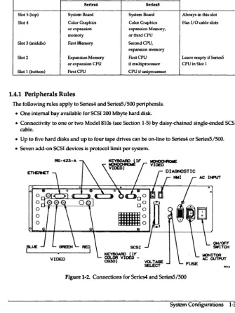
1.4 Series 4 and SeriesS/SOO
[image:16.436.47.383.171.617.2]Board loading is as follows:
Table 1-1. Series4 PC Board Rules
SlolNumber CPUU.ed Comment
Serie.' Seri.IS
Slot 5 (top) System Board System Board Always in this slot
Slot 4 Color Graphics Color Graphics Has I/O cable slots
or expansion expansion Memory,
memory or third CPU
Slot 3 (middle) First Memory Second CPU,
expansion memory
Slot 2 Expansion Memory First CPU Leave empty if Series5 or expansion CPU if multiprocessor CPU in Slot I
Slot 1 (bottom) First CPU CPU if uniprocessor
1.4.1 Peripherals Rules
The following rules apply to Series4 and SeriesS/SOO peripherals.
• One internal bay available for SCSI 200 Mbyte hard disk.
• Connectivity to one or two Model810s (see Section 1-5) by daisy-chained single-ended SCSI cable.
• Up to five hard disks and up to four tape drives can be on-line to Series4 or SeriesS/SOO.
• Seven add-on SCSI devices is protocoilimit per system.
0Q"~~~~~.L,
o
oLJ-r-T-'T----"::...;>(-'
o
o
IBLUE
VOLTAGE SELECT
INPUT
ON/OFF SWITOI
..
,.
Figure 1-2. Connections for Series4 and Series5/S00
Solboume Confidential Information - Do Not Distribute
1.5 Model 810
The Model 810 is the external SCSI peripherals package for the Series4 and SeriesS/SOO. Features of the Model 810 are:
• No boards on the Kbus
• Talks to the host through SCSI cable
• Has its own power supply
• Two half-height SCSI tape drives maximum (or 1 Exabyte 8mm drive)
• Two full height (SY<-inch) shock-mounted SCSI bays (two disk drives maximum)
TAPE DRIVE
TAPE DRIVE
0151( DRIVE
[image:17.433.48.391.26.644.2]1-4 System Configurations
Section
2:
Hardware
2.1 Introduction
This section covers the proprietary backplanes and PCBs used in Solboume Systems.
2.2 Kbus Backplane
General Kbus facts are as follows:• 64 bit data bus/32 bit address bus
• 128 Mbytes/second transfer rate
• Seven slots for Series4 and Series5/600
• Five slots for Series4 and Series5/500
• Temperature sensor above Slot 4 in Series4 and Series5/600
• Slots numbered bottom-up in Series4 and Series5/SOO
• Slots numbered right-ta-Ieft in Series4 and Series5/600
• In Series4 and SeriesS/600, air flow restrictors required on empty slots
• In general, populate the Series4 and Series5/600 bus left-to-right
Solboume Confidential Information - Do Not Distribute
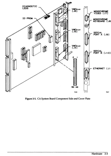
2.3 System Board
Features of the System I/O Board are as follows:
• System EAROM (IDPROM) resident on this board, see illustrations for location. See "Section 5: Boot Environment" for listing of environment variables.
• Monochrome Frame Buffer
- 256 Kbyte Memory
- Supports:1152 by 900 at 69 Hz using 126 Kbyte RAM (not Sun std-mono compatible)
- 1600 by 1280 at 66 Hz using 250 Kbyte RAM (Sun high-res compatible)
• I10ASIC
- Synchronous SCSI, up to 5.0 Mbytes/second transfer rate
- Ethernet in accordance to IEEE 802.3, 10 Mbits/second transfer rate
• Serial Ports
- RS-423-A ports ttya and ttyb, superset of RS-232-C
- RS-232-C compatible
- 57.6 Kbaud asynchronous, 92.1 Kbaud synchronous Data Rates
- Note change in serial port data/stop bit definitions with bootrom versions S4"3.2c and 55-3.3; see Section 9.4: setting up a vt100 on a tty port
• Keyboard and Mouse
- Type 3: 126-key, Engineering-style, Sun4 compatible Keyboard (Cherry)
- Type 4: 107-key, PC-style, Sun4 compatible Keyboard
- 3-button optical mouse (Mouse Systems) with 4 foot cable
• SCSI implementation meets ANSI X3.131-1986, Small Computer System Interface and ANSI X3T9.2/85-53 Rev 4.B Common Command Set (CCS)
• VMEbus
- Three Ribbon Connectors to System Board
- Supports VMEbus Block Mode Transfer
2-2 Hardware
-Cl -Cl -Cl NOTE -Cl -Cl -Cl
Solbourne Confidential Information - Do Not Distribute
DIAGNOSTIC LEOS
"
"
VMEbu. (J6)
VMEbus (J5)
Vt.lEbu8 (J4)
2
.. ..
..
..
..
.. .. ..
.. .. .. ..
.. .. ..
50 49
[image:20.435.44.403.106.610.2]o
Figure 2-1. CA System Board Component Side and Cover Plate
t.IONOCHROt.te: VIDEO (J7)
t.lONOCHROt.ll; KEYBOARD (J8 )
SERIAL PORT A (J9)
SERIAL PORT B (JIO)
ETl-ERNET (J I I )
Solboume Confidential Information - Do Not Distribute
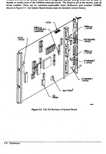
2.3.1 System Board Revision Levels
Version DA/EA of the System Board has a configurable jumper setting which can be used to disable or enable each of the VMEbus interrupt levels. The board is set at the factory with all levels enabled. There are six customer-replaceable fuses (Solboume part number 102888), shown in Figure 2-3. See System Board release notes for detailed version history.
SCSI +5VDC
2-4 Hardware
VMEbu8 INTERRUPT JUMPERS
VMEbu8 -12VDC
.""'''''-_ KEYBOARD
•
[image:21.433.35.388.122.633.2]BATTERY
Figure 2-2. DA/EA Revision of System Board
+5VDC
VMEbu8 +12VDC
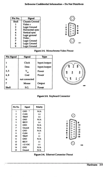
Pin No. Shell 1 2 3 4 5 6 7 8 9 Pin Signal 1 2 3,5 4,8 6 7 Shell PinNa. 1 2 3 4 5 6 7 8 9 10 11 12 13 14 IS
Solboume Confidential Information - Do Not Distribute
[image:22.438.51.396.60.646.2]Signal Chassis Ground Video + Logic Ground Horizontal sync Vertical sync Logic ground Video-Logic Ground Logic Ground Logic Ground I 2 3 4 5
@
@
Figure 2-4. Monochrome Video Pinout
Signal 'JYpe
Clock Input/output
Data Input/output
V cc Power
Gnd Power
not connected
Mouse Output
S.G. Power
Figure 2-S. Keyboard Connector
Signal Polartty
GND' N/A
CLSN (+)
TRMT (+)
0
GND N/A
RECV (+)
GND N/A
Unused N/A
GND N/A
CLSN (.)
TRMT (0)
GND N/A
I 0 0
2 0 0
3 0 0
4
~
0
5 6 o 0
7 0 0
9 o 0
RECV (-)
+12VDC (+)
(S)
GND N/A
Unused N/A
Figure 2-6. Ethernet Connector Pinout 6 7 9 9 9 10 II 12 13 14 15
-""'"
Solboume Ccmf:idential InIormation - Do Not Distribute
Pin No. Signal Description
1 CND (o,assIs CND i. physical ground to AC Ground) connector and beyond.
2 3 4 5 6 7 8 9-19 20 TXO RXD R'rS crs(RTxQ
DSR
Signal Ground (Common)
DCD
Unused
DTR
21-23 Unused
24
2S
TRxC
VERR
TXO i9 data transmitted to the DCE
from lite workstation.
RXO Is data received from the DCE.
NormaUy RTS Is a handshake signal to
the DCE; on CA+ and earlier rev boards, it is connected 10 DTR. elJecliveJy cancelling both signals.
crs is clear 10 send; an incoming signal from DCE indicating Irs ready to acrept data.
Data set (I.e., a modem) ready. SlmUar
to crs, bul used on dift'erent systems.
Reference voltage.
Data carrier detect; modem has received a phone call.
Data terminal ready; a received handshake. On CA+ and earlier rev boards, It is connected to RTS, elJeclively cancelllng both signals.
Exlernal transmit clock.
[image:23.442.46.389.36.517.2]-5 VDC reference signal; used by some modems. I 2 3 4 5 8 7 9 9 10 /I 12 13
Figure 2-6. RS-423-A Serial Port Pinout (1Wo per System Board)
2-6 Hardware
@
0 0 0 0 0 0 0 0 0 0 0 0 0 0 0 0 o o 00 0
Solboume Confidential Information - Do Not Distribute
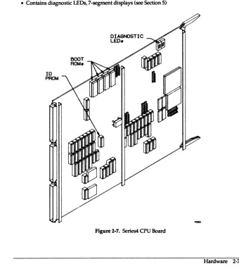
2.4 Series 4 CPU Board
Features of the Series4 CPU Board are as follows:
• 64K direct mapped virtual cache
• 16.67 MHz Fujitsu SP ARC (RISC) MPU with Fujitsu floating point controller
• Weitek 1164/1165 FP chip set: 32 bit single-precision, 64 bit double-precision • Hardware assisted MMU
• Board ID PROM resident, identifies what type of board this is to the system • 64-bit data bus with ECC
• Four 512 by 8 Boot PROMS (located at U3400, U3401, U3402, U3403)
• Contains diagnostic LEOs, 7-segment displays (see Section 5)
BOOT ROM.
DIAGNOSTIC
LED.
Figure 2-7. Series4 CPU Board
[image:24.432.52.392.227.622.2]Solbourne Confidential Information - Do Not Distribute
2.5
Series
5 CPU BoardFeatures of the Series5 CPU Board are as follows:
• 128K direct mapped physical cache
• 33.33 MHz Cypress SP ARC (RISe) MPU with Weitek 3171 floating point unit
• Two level MMU, Fast and Global TLB
• Fast RIO Cycle
• Board-resident ID PROM identifies what type of board this is to the system
• 64-bit data bus with Eee
• Supports up to 256 Mbyte of RAM
• Four 512 by 8 Boot PROMS (located at U3400, U3401, U3402, U3403)
• Contains diagnostic LEOs, seven-segment displays (see Section 5)
ID
PROM
2-8 Hardware
BOOT ROMs
[image:25.438.47.388.243.631.2]DIAGNOSTIC LEOs
Solboume Confidential Information - Do Not Distribute
2.6 CG 40 and CG30 Color Frame Buffer Boards
Features of the Color Frame Buffer Boards are as follows:KEYBOARD
SYNC (NOT USED)
RED (J5)
GREEN (J6)
BLUE (J7)
Features of the CG 40 Color Frame Buffer Board are as follows:
• Discontinued, but supported
• Simultaneous display of 256 colors from a palette of more than 16.7 million
• BNC outputs: sync, red, green, blue Sync is imbedded in the green line, not a separate line
• Eight bit color storage, two bit overlay storage
Features of the CG 30 Color Frame Buffer are:
• Simultaneous display of 256 colors from a palette of more that 16.7 million
• BNC outputs: sync, red, green, blue
• Sync is imbedded in the green line, not a separate line
• Hardware support for cursor operations in X
• Hardware assist for Bit Bit operations
Figure 2-9. CG 30 Color Board Cover Plate
Solboume Con6dentiallnformation - Do Not Distribute
2.7 Memory Boards
Features of the Memory Board product line are as follows:
• ECC memory sold in 16 Mbyte increments
• ECC memory available in 16 Mbyte, 32 Mbyte, and 128 Mbyte boards
• 72 bit {64 data and 8 check bits) Kbus data interface
• 32 byte cache block memory transactions
• Software settable base address
• Software settable enables for memory reads and writes
• Board-resident ID PROM identifies what type of board this is to the system
2.8 VMEbus backplane
Features of the Solbourne VMEbus implementation are as follows:
• Seven slots, numbered from center of machine
• Bandwidth of 25 MByte
• Slot priority, with slot 1 having highest priority
• Card cage houses 6u "eurocard" format boards
• See the Series4 and Series5/600 Service Manual, Section 5, for more VMEbus information on backplane layout, connector specifications, signal termination, and bus arbitration
2-10 Hardware
SLOT 7
Vt.tEbU8 CARDCASE
SLOT I
Kbu8 CARDCAGE
[image:27.432.47.385.37.365.2]'''''.
Solboume Confidential Information - Do Not Distribute
2.9 SCSI
Features of the Solboume SCSI implementation are as follows:
• SCSI bus is terminated on both ends, at System Board and chassis SCSI port
• No tennination is required or used on any installed disk drive
• Maximum cable length of 6 meters, including internal and external length
Table 2-1. SCSI Connector Pin Assignments Pin No. Signal Pin No. Signal
1 Ground 2 -Data Bus 0' 3 Ground 4 -Data Bus 1 5 Ground 6 -Data Bus 2 7 Ground 8 -Data Bus 3 9 Ground 10 -Data Bus 4 11 Ground 12 -Data Bus 5 13 Ground 14 -Data Bus 6 15 Ground 16 -Data Bus 7 17 Ground 18 -Data BusP 19 Ground 20 Ground 21 Ground 22 Ground 23 Ground 24 Ground 25 Open 26 Termination Power 27 Ground 28 Ground 29 Ground 30 Ground 31 Ground 32 -Attention
33 Ground 34 Ground 35 Ground 36 -Busy
37 Ground 38 -Acknowledge 39 Ground 40 -Reset 41 Ground 42 -Message
43 Ground 44 -Select 45 Ground 46 -Control/Data 47 Ground 48 -Request 49 Ground 50 -lnput/Oulp\ll
26 50
ct=;
{IIIIIIIIIIIIIIIIIIIIIIIII\
ID
I 25
Figure 2-10. SCSI External Port
, A dash means active low.
Solboume Confidential Information - Do Not Distribute
2.10 Field Notes
Section 3: Peripherals: Disk Drives, Tape Drives, and Controllers
3.1 Introduction
This section gives configuration infonnation on Solboume's current peripherals offerings. The following peripheral devices are detailed in this section:
Table 3-1. Solboume Peripherals
Type Mir Model Interface Form Factor Formatted
Capacity
Disk Maxtor LXT·200 SCSI 3lO-inch 200 Mbytes
Disk Maxtor XT-438ffi SCSI SY..-inch Full 327 Mbytes Disk Maxtor XT-876ffi SCSI 5lO-inch Full 661 Mbytes Disk Hitachi DKSI4C-38 SCSI 5lO-inch Full 327 Mbytes Disk I-litachi DKSI5C-78C SCSI SY..-inch Full 661 Mbytes
Disk Fujitsu M2383K VMEbus/SMD 8 inch 830 Mbytes
Disk Seagate Sabre 972()'1230 VMEbus/SMD 8 inch 1040 Mbytes
Tape Archive 206m SCSI SY.inch Hall 60 Mbytes/cart.
Tape Archive 21505 SCSI 5Y.inch Hall 150 Mbytes/carl
Tape H-P 887808 SCSI lO-inch tape 140 Mbytes/reel
Tape Exabyte EX8-8200 SCSI 8mm tape 2 Gbyles/carl
Controller Xylogics 753 VMEbus N/A N/A
Controller Interphase 4207Eag1e VMEbus N/A N/A
Controller Solbourne/ VME/16 Une MUX VMEbus N/A N/A
Xylogics
Solboume Confidential Information - Do Not Distribute
3.2 Maxtor LXT-200 200 Mbyte Hard Disk
This section describes the Maxtor 200 Mbyte disk.
Features of the LXT-200 are as follows:
• 200 Mbytes formatted capacity
• Fits in /500 chassis
• 15 milliseconds average seek time
• 9.2-14.8 Mbit/sec data transfer rate from disk
• 4 Mbyte/sec data transfer rate (synchronous) on SCSI bus
• 32 Kbyte buffer
FRONT OF DRIVE
Figure3-1. LXT-200PCB
3-2 Peripherals: Disk Drives, Tape Drives, and Controllers
1°1
8 9 7 6 0 0 5jigSI {4
0 0 :5Solboume Confidential Information - Do Not Distribute
Table 3-2. LXT -2005 Address Jumpers
SCSI Pin Pair Pin Pair Pin Pair Comments
Address 516 3/4 112
0 out out out Lowest priority; default setting
1 out out in
2 out in out
3 out in in
4 in out out Reserved for tape drive
5 in out in Reserved for tape drive
6 in in out Reserved
7 in in in Reserved for controller
3.2.1 LXT-200 format.dat
The following information is in format.dat for the LXT-2OO.
disk_type = "Maxtor LXT-200" ctlr = IOASIC
ncyl
=
1300 : acyl=
2 : pcyl=
1314 rpm = 3600 : bpt = 22528cache
=
OxOO : nzone=
3 : atrks=
0 partition =; "Maxtor LXT-200"disk = "Maxtor LXT-200" : ctlr IOASIC nhead
a
=
0, 17157 : b=
57, 66220 : c=
0, 391300 g = 340, 2889607 nsect 43
d 277, 18963
Solbourne Confidential Information - Do Not Distribute
3.3 Maxtor XT -4380S SCSI 5 Yt-inch Full Height 327 Mbyte Disk This section describes the XT -43805. Features of the XT -43805 are:
• 327 Mbytes fonnatted capacity • Fits in Model 810 and /600 chassis • 18 milliseconds average seek time • 10 Mbit/sec data transfer rate from disk
• 4 Mbyte/sec data transfer rate (synchronous) on SCSI bus • 64 Kbyte buffer
Figure 3-2. XT -43805 TLA 1094448 PCB
Table 3-3. XT -43805 Address Jumper Settings (All TLAs)
SCSI Addr ••• JP37 JP36 JP35
0 out out out
1 out out in
2 oul in out
3 out in in
4 in out out
5 in out in
6 in in out
7 in in in
Solboume CcmfidentiallnfOl'Dlation - Do Not Distribute
3.3.1
XT -43805 format.dat
The following infonnation is in fonnat.dat for the XT -4380S.
JPI8
disk_type "" "Maxtor XT-4380S"
ctlr = IOASIC : fmt_time = 3
ncy1 = 1218 : acyl = 2 : pcy1 1224 nhead = 15 nsect 35 rpm - 3600 : bpt - 20833
cache = Oxll partition "Maxtor XT-4380S"
disk = "Maxtor XT-4380S· : ctlr = IOASIC
a = 0, 16800 : b = 32, 66150 : c = 0, 639450 d 158, 19425 9 = 195, 537075
E6 0
E5 0
JPI ... 0
o o
D
D
t----i= . . . .
D~
D D
"~---r---~
TERMINATING RESISTOR SOCKETS
[~
g
r----11 I
JP3e 0 0 JP37 0 0
DO DO
Figure3-3. XT-4380STLAs 1094708 and 1094868 PCB
D
o 0 0 JP26
....
Solboume Codidentiallnformation - Do Not Distribute
3.4 Maxtor XT -8760S SCSI 5
~-inchFull Height 661 Mbyte Disk
This section describes the XT -8760S .. Features of the XT -8760S. are:• 661 Mbytes fonnatted capacity
• Fits in Model 810 and /600 chassis
• 18 milliseconds average seek time
• 15 Mbit/sec data transfer rate from disk
• 4 Mbyte/sec data transfer rate (synchronous) on SCSI bus
• 64 Kbyte buffer
JPIIO
JP~
~~---i---
______
4-__
~~JPRJP40·m.;,;:Iill"'_.1..J I
....
Figure 3-4. XT -8760S PCB
Solboume Confidential Information - Do Not Distribute
Table 3-4. SCSI Device Identifier Jumpers on the XT-8760S
SCSI JP37 JP36 JP35 Address
0 out out out
1 out out in
2 out in out
3 out in in
4 in out out
5 in out in
6 in in out
7 in in in
3.4.1 XT -87608 format.dat
The following infonnation is in fonnat.dat for the XT-8760S.
disk_type = "Maxtor XT-8760S"
partition
ctlr
=
IOASIC : fmt time=
3 ncyl = 1626 : acyl = 2 : pcyl rpm = 3600 : bpt = 31410 cache = Ox11"Maxtor XT-8760S"
1632 nhead
disk = "Maxtor XT-8760S" : ctlr = IOASIC a = 0, 16695 : b = 21, 66780 : c = 0, 1292670 g = 129, 1190115
15 nsect 53
d 105, 19080
Solboume Confidential Information - Do Not Disbibute
3.5 Hitachi DK514C-38 SCSI 5 Yo-Inch Full-height 327 Mbyte Disk
This section describes the DKSI4C-38. Features of the DKSI4C-38 are:
• 327 Mbytes formatted capacity
• Only works on OS/MP 4.OC and up • Fits in the Model 810 and 1600 chassis
• 16 milliseconds average seek time
• 4 Mbyte/sec data transfer rate (synchronous) on SCSI bus
JP2S4
JP292
t
2 0 0 II~LE
10 0 0 93-1 8 0 0 7
CHECK
6~
5... 0 0 3
F.U.O.· 2 I
F.U.O.· {
LEGEND.
SCSI COI\NECTOR
o
Cl-ECK
B
= ND JUMPER CHECK I~I = JUMPERSEE TABLE r;;-;;l
=
LOOK UP JUt.f"ER L-.::J PLACEMENT IN TABLE [image:37.436.43.391.73.638.2]F.U.O.· ~
Figure 3-5. DKS14C-38 PCB
3-8 Peripherals: Disk Drives, Tape Drives, and Controllers
Solboume Confidential Information - Do Not Distribute
Table 3-5. SCSI Address on Jumper JP292
SCSIID Pins 7-8 Pins 9·10 Pins 11·12 Comment
0 in in in Default
1 in in out
2 in out in
3 in out out
4 out in in
5 out in out
6 out out in
7 out out out Reserved
3.5.1 DKS14C-38 format.dat
The following information is in format.dat for the DKS14C-38.
disk_type = "Hitachi DK514C-38"
partition
ctlr = IOASIC : fmt_time = 3 ncyl = 896 : acyl = 2 : pcyl rpm = 3600 : bpt = 226112 cache = Ox11
"Hitachi DK514C-38"
898 nhead
disk = "Hitachi DK514C-38 " : ctlr = IOASIC a
=
0, 16422 : b=
23, 66402 : c=
0, 639744 g = 143, 53692814 nsect 51
d = 116, 19278
Solbourne Confidential Information - Do Not Distribute
3.6 Hitachi DKS1SC-78C SCSI 5 'I.-Inch Full-height 661 Mbyte Disk
This section describes the DK51SC-7SC. Features of the DKS1SC-7SC are:
• 661 Mbytes formatted capacity
• Only works on OS IMP 4.OC and up
• Fits in the ModelS10 and 1600 chassis • 16 milliseconds average seek time
• 4 Mbyte/sec data transfer rate (synchronous) on SCSI bus
F.U.O.·
ct£CK
F.U.O.·
.
ct£CK
JP223 F.U.O.· F.U.O.·
ODD
DO
CHECK if:Z0Z1I--Ir---
CJ
D
JP266
CHECK
J8 CHECK
f ' I
LEGENO.
CHECKB NO JUMPER SEE T r:::-:1
=
LOOK UP JUMPER AflLE ~ PLACEMENT IN TABLE [image:39.435.46.392.209.605.2]CHECK r~1 JUMPER F.U.O.· ~
Figure 3-6. DKS1SC-7SC PCB
3-10 Peripherals: Disk Drives, Tape Drives, and Controllers
Solboume Confidential Information - Do Not Distribute
Table 3-6. Jumper JS SCSI Address ,
SCSIID Pins 5-6 Pins 7-S Pins 9-10 Comment
0 out out out Default
1 out out in
2 out in out
3 out in in
4 in out out
5 in out in
6 in in out
7 in in in Reserved
3.6.1 DK515C-78C format.dat
The following information is in format.dat for the DKS1SC-7SC.
disk_type = "Hitachi DK515C-78"
partition
ctlr = IOASIC : fmt time = 3 ncyl = 1339 : acyl = 2 : pcyl rpm = 3600 : bpt = 35328 cache = Oxll
"Hitachi DK515C-78"
1356 nhead
disk = "Hitachi DK515C-78" : ctlr = IOASIC a = 0, 17388 : b = 18, 66654 : c = 0, 1293474 g = 107, 1190112
14 nsect 69
d = 87, 19320
Solboume Confidential Information - Do Not Distribute
3.7 Fujitsu M2382K SMD 8-inch 830 Mbyte Disk
This section describes the M2382K. Features of the M2382K are:
• 830 Mbytes formatted capacity
• Fits in Model 820 chassis (up to 4 per chassis)
• 3 Mbyte/sec data transfer rate from disk
[image:41.433.37.389.32.611.2]• 16 milliseconds average seek time
Figure 3-7. M2382K DIPs
Solboume Confidential Information - Do Not Distribute
PHYSICAL PHYSICAL PHYSICAL DEVICE 0 DEVICE I DEVICE 2
2~
I~2~
I -=:::J2~
I~ [image:42.433.50.387.219.629.2]ON OFF ON OFF ON OFF
Figure 3-8. M2382K Address Settings
3.7.1 M2382K forrnat.dat
The following information is in fonnat.dat for the M2382K.
disk_type = "Fujitsu M2382K" ctlr = XD753
PHYSICAL DEVICE :5
2~
I -=:::JON OFF
200"1
: ncyl = 743 acyl = 2 : pcyl = 745 : nhead = 27 nsect 81
partition
: rpm = 3600 : bpt = 49728 : bps = 604 "Fujitsu M2382K"
disk = "Fujitsu M2382K" : ctlr = XD753 a 0, 17496 : b = 8, 65610 : c = 0, 1624941 g = 47, 1522152
Peripherals: Disk Drives, Tape Drives, and Contrr
Solbourne Confidential Information - Do Not Distribute
3.8 Seagate Sabre 9720-1230 SMD 8-inch One Gbyte Disk
This section describes the Sabre 9720-1230. Features of the Sabre 9720-1230 are:
• 1040 Mbytes formatted capacity
• Fits in Model 820 chassis (up to 4 per chassis, combinations with Fujitsu allowed)
• 3 Mbytcs/sec data transfer rate from disk
[image:43.435.51.388.39.639.2]• 16 milliseconds average seek time
Figure 3-9. Sabre 9720-1230 PCB
3-14 Peripherals: Disk Drives, Thpc Drives, and Controllers
Solbourne Confidential Information - Do Not Distribute
PHYSICAL DEVICE 0
2 :3
4-PHYSICAL DEVICE I
2 3
4-PHYSICAL DEVICE 2
2 3
4-Figure 3-10. Sabre 9720-1230 Address Settings
3.S.1 Sabre 9720-1230 format.dat
The following information is in format.dat for the Sabre 9720-1230.
"Sabre 9720-1230-1GB" ctlr = XD753
PHYSICAL DEVICE :3
2 :3
4-: neyl = 1633 : acyl = 2 : pcyl : rpm = 3600 : bpt = 50400 : bps
1635 : nhead = 15 : nsect 599 : bfi_skew = 8 partition "Sabre 9720-1230-1GB-599"
disk = "Sabre 9720-1230-1GB-599" a = 0, 17430 : b = 14, 65985 : c g = 83, 1929750
ctlr = XD753
0, 2033085 : d 67, 19920
Peripherals: Disk Drives, Tape Drives, and Controllers 3-15
Solboume Collfidential Information - Do Not Distribute
3.9 Archive 2060S QIC-24 and 21SOS QIC-1SO Half-height, Yo-Inch Tape Drive
This section describes the Archive 20605. Features of the Archive 20605 are:
• Fits in Model 810 and /600 chassis
• 1.25 Mbyte/sec data transfer rate (asynchronous) on SCSI bus
• 20605 has 60 Mbyte capacity using DC-600A or 600 XTD cartridges
• 21505 has 150 Mbyte capacity using DC-600A or 600 XTD cartridges
[image:45.432.50.389.80.610.2]o
...
. . . .
. .
.
.
. .
. . .
.
. . .
.
. . .
.
.
[QQ] [Q:Q] rl50l
PEN
Cl'o-me-00 00 00
DIAS Cl'1 IDI
00 ~ 00
JUMPER BLOCK
COIllECTOA
KEY SCSI CONIIECTOR
Figure 3-11. Archive 20605 and 21505 Jumpers
Table 3-7. SCSI Address Jumpers on Archive Drives
SCSI Address ID2 IDI IDO
0 out out out
1 out out in
2 out in out
3 out in in
4 in out out
5 in out in
6 in in out
7 in in in
Solboume Confidential Information - Do Not Distribute
3.10 Exabyte EX8-8200 SCSI 5 'I.-Inch full height 8 mm Cartridge Tape
This section describes the Exabyte EXB-82oo. Features of the Exabyte EXB-82oo are:
• Fits in Model 810, 1600, and Model 820 chassis.
• 1.5 Mbyte/sec data transfer rate (asynchronous) on SCSI bus
• 2 Gigabyte capacity per standard 8rnm video cartridge
2 ;5
AODRESS ...
2 ;5
AOORESS 5
.,.,v.
Figure 3-12. Exabyte EXB-82oo Jumpers
Solboume Confidential Information - Do Not Distribute
3.11 H-P 88780B SCSI V,-Inch Reel Tape Drive
This section describes the H-P 88780B. Features of the H-P 88780B are:
• 198 Kbytes/sec data transfer rate@ 1600 bpi PE (Phase Encoded)
• 747 Kbytes/sec data transfer rate @ 6250 bpi GCR (Group-Coded Recording)
• 93 Kbytes/sec data transfer rate @ 800 bpi NRZI (Non-Return to Zero Inverted)
• 512 Kbyte cache buffer
• 125 ips nominal tape speed
• SCSI cable is connected to either SCSI connector on the back of drive
3.11.1 Changing the 88780B's SCSI Address
To change to another SCSI address, follow these steps:
1. Take the drive offline.
2. Press OPTION to enter the Option Mdde. TEST * appears in the display.
3. Press NEXT until ADDR * or ID • appears in the display. ADDR' appears if you have a Pertec-compatible interface, ID' appears if you have a SCSI interface.
4. Press ENTER.
5. Using NEXT or PREY, bring the ADDRESS/ID number desired into the display.
6. Press ENTER. The ADDRESS/ID you selected appears as SET <#>.
[image:47.438.50.372.48.374.2]7. Leave the Option Mode by pressing OPTION or RESET.
Table 3-8. Idev Entries for the H-P 88780B
Device Name SCSI Address Density
rstO/rmtO Ox4 1600 (PE)
rstl/rmtl OXS 1600 (PE)
rst8/rmtB Ox4 6250 (GCR)
rst9/rmt9 Ox5 6250 (GCR)
rst16/rmt16 Ox4 BOO (NRZI)
rst17/rmt17 OXS BOO (NRZl)
Solboume Confidential Information - Do Not Distribute
3.12 Xylogics 753 Controller Board
This section details the Xylogics 753.FEDCBA987654 JA
[image:48.437.66.384.145.637.2]""
...
Figure 3-13. Jumper Settings on the Xylogics 753
11 bl 3 9 X I . a e - oglcs Ba se Add ress Sel echon
Address F E D C B A 9 8 7
OxEESO 0 0 0 I 0 0 0 I 0
OxEE90 0 0 0 I 0 0 0 I 0
OxEEaO 0 0 0 I 0 0 0 I 0
OxEEbO 0 0 0 I 0 0 0 I 0
LJ
...
... JD
6 5
I I
I I
I 0
I 0
1010
,
I
0
I
0
Solboume Confidential Information - Do Not Distribute
3.13 VMEbusl16 Line Multiplexer
This section describes the VMEbus/16 Line Multiplexer. Features of the VMEbus/16 Line Multiplexer are:
• Adds 16 asynchronous channels per board, housed in one 6U-sized VME slot
• Up to 64 channels, four boards, in one /600 or /800 system
• Supports devices such as terminals, line or laser printers, and modems
• Each channel can transfer data at rates ranging from 50 baud to 38.4 Kbaud
• Devices appear as ttyXY where X is the controller # and Y is the port on the controller; e.g. tty12 is the 3rd port (2) on the 2nd Mux card (1).
[image:49.432.52.385.221.608.2]100II
Figure 3-14. Solboume Multiplexer Board Default Jumper Settings
3-20 Peripherals: Disk Drives, Tape Drives, and Controllers
2
Solboume Confidential Information - Do Not Distribute
Table 3-10. MUXJumper Meanings
Jumper Name Purpose Set by Whom
JA Crystal speed selection User
JB VMEbus address Solbourne factory
JC VMEbusaddress Solbourne factory
JD VMEbus address User
JE Bus Request/grant Solbourne factory
JF Bus request/grant Solbourne factory
JG Bus request/grant 'Solbourne factory
JH Crystal Speed/Diagnostics Uscr
JJ ROM size Solbourne factory
Table 3-7 shows the settings on jumpers JA and JH that are reqUired to change the board's crystal speed.
Table 3-11. Line Rate Per Jumper Positions
line Rate Jumper Positions
0 JA: jumper pin 2 to 3 JH: no jumper between 1 and 2
1 JA: jumper pin 1 to 2 JH: jumper pin 1 to 2
Table 3-12. Setting Jumper JD for VMEbus Addresses
Board Addre •• Pin 4 PinS Pin 6 Pin 7
Number
0 0.0620 in out in in
1 0.0640 in in out in
2 0.0660 in out out in
3 0.0680 in in in out
[image:50.433.60.400.310.619.2]Solbourne Confidential Information - Do Not Distribute
3.14 Interphase Eagle 4207 Ethernet Board
This section details the Eagle 4207.
JA2 (DAUGlfTER BOARD) ) JAI (DAUGHTER BOARD)
DAUGHTER IlOARD
I IL-=:J I -=:J
2 -=:J 2 -=:J
3 -=:J 3 -=:J
4 -=:J 4 -=:J 5 -=:J 5 -=:J
6 -=:J 6 -=:J
7 -=:J 7 -=:J
8 -=:J 8 -=:J
Clf"F ON OFF ON
SWITCH 3 SWITCH 2
I 2 3 4 5 6 7 8
=
=
=
=
=
==
=
=
==
=
=
==
=
R::::J ~ ~ -=:J ~ -=:J -=:J ~OFF ON
SWITCH I
0
I
2
3
[image:51.436.42.385.65.610.2]JA4 JA5
Figure 3-15. Jumper Settings on the Eagle 4207
Table 3-13. Eagle Jumper Block and Switch Functions
Jumper Block/Switch Number Function
JA 2 - daughter board Full/half A VI power JA 1 - daughter board Transceiver power
JAI Factory test
JA2 Factory test
JA3 EPROM size
JA4,5,6 VMEbus request level
Switches 1,2,3 Configuration switches
3~22 Peripherals: Disk Drives, Tape Drives, and Controllers
Section 4: Environmental Data
4.1 Power Ratings, BTU Ratings, and Amperage Requirements
The following table gives the power ratings, BTU ratings, and Amperage requirements for Solboume products.
Solboume Products
Power Ratings, BTU Ratings, Amperage Requirements
Solboume Typ Rated Typical Slow-Blow ReqAmp
Model Amps Volts BTU/hour Fuse Rating Service
/600 7.87 110/120 3088 12A 1SA
/600 4.25 220/240 3335 6A
820 6.18 110/120 2425 12A 12A
820 3.91 220/240 3068 6A
/500 5.56 110/120 2182 lOA 12A
/500 2.78 220/240 2182 6A
810 1.07 110/120 420 6A lOA
810 0.65 220/240 510 3A
19"Color(140w) 100/120 478 4A 6A
19" Color(140w) 220/240 478 3.15A SA
16" Color(140w) 100/120 478 4A 6A
16" Color(l40w) 220/240 478 3.15A SA
New Monochrome(l00w) 110/120 341 l.5A 3A
New Monochrome(100w) 220/240 341 0.8A 2A
H-P 88780B Yo" Tape 100/120 850 n/a 3A
H-P 88780B W' Tape 200/240 850 n/a 2A
Notes:
Typ Amps = Measured amperage during UL tests, fully card-populated. Typ BTU/hour
=
[email protected] BTU/hr/watt usingTyp Amp figures. Slow-Blow Fuse Rating = Maximum draw; Nominal Amp Rating. Max BTU @ Fuse Rate=
Calculated BTU /hr based on Fuse Rating. Figures for individual components/c~s not available at this time.Max BTU @ Fuse Rate 4708 4708
4708 4708
3924 4708
2354 2354
1569 2472
1569 2472
589 628
1280 1280
Solbourne Confidential Information - Do Not Distribute
4.2 Operating Temperature
The numbers in this section were taken from the product installation manuals.
• For /500, /600
Power on: +10° to +40° C (+50° to+t04°F) Power off _20° to +75° C (-40 to +167° F)
• For /8tO
Power on: + tOO to +35° C (+50° to +95° F) Power off -200 to +75° C (-40 to +167° F)
• For /820
Power on: +10° to +30° C (+50° to +86° F) Power off -40° to +60° C (-40° to +140° F)
• Maximum Temperature Gradient(w /0 tape}: 15° C (59° F) per hour Maximum Temperature Gradient(w tape}: 5° C (41 ° F) per hour
4.3 All Disk Drives: Special Handling for Temperature Changes
When bringing the drive package in from outside, prevent condensation on the drive by allowing the drive to warm up to room temperature before opening the plastic covering. Allow one hour for each 18° F of temperature difference. For example, if it is 20° F outside and 70° F inside (a 50° F difference) wait about 3 hours (50/18 = 2.77 hours) to warm up the drive before opening.
4.4 Operating Humidity
Power on: 20% to 80%, non-condensing at 400 C Power off Up to 9S%F, non-condensing at 40° C
4.5 Regulation Certification
UL 478, CSA 220, TUV (qualified "GS" mark) FCC-A
CISPR-22A (VCCI-A)
VDE-A("qualified pass" with Series 5) X-ray Emit - DHHS Rule 21 (subchapter]), PTB
CSA on SeriesN /600 and Model 820 expected May 1990.
4.6 Field Notes
Section 5: Boot Environment
5.1 EAROM Environment Variables
EAROM environment variables visible at ROM prompt via 'printenv':
Read-only variable set in manufacturing, specifies host ID
Read-only variable set in manufacturing, specifies serial t Read-only variable set in manufacturing, specifies Ethernet addr HOSTID
SERIAL ENETADDR
MODEL Read-only variable set in manufacturing, specifies unit model PORT A BAUD
PORT B BAUD BOOTMODE DISPLAYRES MASTER DIAGBOOT DEFAULTBOOT CONSOLE DEFAULTSWAP DEFAULTROOT
Specified the baud rate for ttya (defaults to 9600) Specified the baud rate for ttyb (defaults to 9600)
Cold and warm reset action - auto (default) or manual
Resolution of the console display, defaults to 1152x900
Defines master CPU slot #, defaults to lowest s l o t '
Where to boot diagnostics from, defaults to sd.si(, ,6)stand/dg Where to boot UNIX from, defaults to sd.si()/vmunix
Type of console: zs() or fb()
Specifies swap partition, defaults to sd.si(, ,1) Specifies root partition, defaults to sd.si()
To print all the environment variables' values, at the ROM prompt, type:
ROM> pr (for printenv)
envedit
The first four variables can only be entered once; after that they are only alterable with the "envedit" program on a tape cartridge.
At the ROM prompt, insert "envedit" tape and type:
ROM> b st.si(,4,) (for tape drives with an address of 4)
Enter the name of the variable to change, thenlReturnl Enter the new value, then IRetumliRetuml to exit "envedit."
5.2 BOOT ROM Command List
The BOOT ROM accepts various commands to boot and start programs, display and change contents of memory, & display and change environment variables.
The following UNIX commands are available at the ROM prompt: For more information on these commands and their options see bootrom (8)
b go
boots the program specified by DEFAULTROOT or DIAGBOOT starts the program from the entry point
examine deposit printenv setenv unsetenv cp mode reset help ? rdg date
Is
Solboume Confidential Information - Do Not Distribute
displays the contents of ranges of memory
changes the contents of memory at a specified address displays the value of a named environment variable changes the value of a named environment variable deletes the value of a named environment variable copies the contents of a source file to a destination file
changes the access mode used by examine and deposit commands calls the rom reset routine, i.e. cold, warm, halt, autoboot prints the syntax of the command specified
same as 'help'
invokes the Extended ROM Diagnostic Program without an argument, displays the current date and time otherwise, current date is set as specified by argument prints a list of files in a specified directory
5.3 Boot Command Options
-s Single user -w Write -a Interactive -b Skip rc.boot
-m n Limit available memory to
'n
MBytes -M Master CPU only-d Boots to the program specified by the DIAGBOOT environment variable
5.4 Booting from Specific Devices
The boot command has the syntax:
ROM> b device(parameters)pathname args
Booting from a disk other than the specified default:
ROM> b tape(controller, unit, filenumber)pathname args
An example of booting from tape:
ROM> b st.si(,4,) -a
The above example example boots from the first file (0), drive address 4, controIler 0 in interactive mode.
Booting from a disk other than the specified default:
ROM> b controller(address, drive, partition)pathname args
An example of booting from an alternative disk:
ROM> b sd.si()/vmunix.test
The above example boots from the first file (0); drive 0, controIler 0, to the file named vmunix.test
Solbourne Confidential Information - Do Not Distribute
Booting to a 4.OC Release Tape, using a local tape drive:
ROM> b st. s1 (,4,2) -swabM for Series4, use st.si(,4,3)
rootfilesystem type ( spec 4.2 nfs 10 ) : 4.2 root device ( sd%d[a-h] ns%d[a-h] rd%d[a-h]) rdOa initialize ram disk from device ( st%d[a-h] ... ) : stO file number : 5
swap filesystem type ( spec 4.2 nfs 10 ) : spec swap device ( sd%d[a-h] ns%d[a-h) ... ) : nsOb
5.5 Device_name/ProtocoCnarne Abbreviations
sd SCSI disk st SCSI tape
si SCSI I/O ASIC controller ei Ethernet I/O ASIC
xd Xylogics disk (SMD) controller
xs Zilog 8530 serial controller chip (keyboard and mouse) zs Serial communication ports:
zsO -> keyboard and mouse
zsl -> ttya & ttyb
sr SCSI rimfire (made by Ciprico), no longer a supported hardware device
5.6 BOOT ROM Versions 3.2c (Series4) and 3.3 (Series5)
Data/stop bits change with these versions to be compatible with UNIX. Is: 7data/2stop bits
Was (in previous versions): Sdata/lstop bits
5.7 Init daemon and System Initialization Scripts
This is the last step in the boot process
1. init(S) runs re.boot (S)
2. rc.boot sets the machine's name. Then, if the system is to come up multiuser, it invokes fsck (8) with the preen option (-p).
3. fsck checks the disks for inconsistencies.
4. If fsck does not report problems, init invokes re (S). If fsek does detect a serious problem, init brings the system up single user. When you press (Control-Df to leave single user mode, re (S) is invoked.
5. rc mounts file systems on the machine's local disks (4.2 mounts), if any. Then it passes control to re.loeal.
6. re.loeal starts daemons on the local machine that handle NFS, YP, and mail requests. It mounts file systems that the machine accesses over the network (NFS mounts). Finally, it returns control to re.
Solboume Confidential Information - Do Not Distribute
7. re starts up standard daemons, preserves editor files, and initiates other system activities, such as starting the network or system accounting, if applicable to the currently booting machine.
8. When re finishes running, the system comes up in multiuser.
5.8 Field Notes
Section 6: Man Pages on Key System Administration Files
6.1 Introduction
The following key system administration man pages are given in this section:
Command Page
ethers (5) 6-2
exports (5) 6-3
fstab (5) 6-5
group (5) 6-7
hosts (5) 6-9
hosts.equiv (5) 6-10
inetd.conf (5) 6-12
networks (5) 6-13
netgroup (5) 6-14
passwd(5) 6-15
printcap (5) 6-17
rpc(5) 6-20
services (5) 6-21
termcap (5) 6-22
ttytab(5) 6-24
ETHERS(S) FILE FORMATS ETHERS(S)
NAME
ethers - Ethernet address to hostname database or YP domain
DESCRIPTION
FILES
The ethers file contains information regarding the known (48 bit) Ethernet addresses of hosts on the Internet. For each host on an Ethernet, a single line should be present with
the following information: .
Ethernet address official host name
Items are separated by any number of blanks and/or TAB characters. A '#' indicates the beginning of a comment extending to the end of line.
The standard form for Ethernet addresses is "x:x:x:x:x:x" where x is a hexadecimal number between 0 and ff, representing one byte. The address bytes are always in net-work order. Host names may contain any printable character other than a SPACE, TAB, NEWLINE, or comment character. It is intended that host names in the ethers file correspond to the host names in the hosts(S) file.
The ethecIine() routine from the Ethernet address manipulation library, ethers(3N) may be used to scan lines of the ethers file.
tetclethers SEE ALSO
ethers(3N), hosts(S)
EXPORTS(5) FILE FORMATS EXPORTS(5)
NAME
exports, xtab - directories to export to NFS clients
SYNOPSIS letc/exports
letc/xtab
DESCRIPTION
The letc/exports file contains entries for directories that can be exported to NFS clients. This file is read automatically by the exportfs(8) command. If you change this file, you must run exportfs(8) for the changes to affect the daemon's operation.
Only when this file is present at boot time does the rc.local script execute ex,portfs(8) and start the NFS file-system daemon, rusd(8).
The letc/xtab file contains entries for directories that are currently exported. This file should only be accessed by programs using getexportent (see exportent(3». (Use the -u option of exportfs to remove entries from this file).
An entry for a directory consists of a line of the following form:
directory -option!, option I ...
directory option
SoJbourne Computer, Inc.
is the pathname of a directory (or file).
is one of
ro Export the directory read-only. If not specified, the direc-tory is exported read-write.
rw=hostnames[:hostname] ...
Export the directory read-mostly. Read-mostly means read-only to most machines, but read-write to those specified. If not specified, the directory is exported read-write to all.
anon=uid
If a request comes from an unknown user, use uid as the effective user lD. Note: root users (uid 0) are always con-sidered "unknown" by the NFS server, unless they are included in the "root" option below. The default value for this option is -2. Setting "anon" to -1 disables anonymous access. Note: by default secure NFS will accept insecure requests as anonymous, and those wishing for extra secu-rity can disable this feature by setting "anon" to-1.
root=hostnames[:hostname] ..•
Give root access only to the root users from a specified
hostname. The default is for no hosts to be granted root access.
access=C/ient [:client I ...
Give mount access to each client listed. A client can either be a hostname, or a netgroup (see netgroup(5». Each
client in the list is first checked for in the net group data-base, and then the hosts database. The default value allows any machine to mount the given directory.
secure Require clients to use a more secure prbtocol when access-ing the directory.