-APPLE PRODUCTS INFORMATION PKG.
-ASTEC POWER
SUPPLIES--ORIGINATOR: Larry Sovulewski DATE: 6-Aug-82
POWER SUPPLY SCHEMATICS AND COMPONENT LAYOITS
---Apple J L
--Astec AAl1040
Astec AAI1040/B
Apple 1//
--Astec AAl1190
Profile //1 --Astec AAlI770
Astec AA117701 A As tec AAll771
...
...•...•..•..•....
...•...
...•...•...•...•....
...
...
•...•••.•.••..•.•..
POWER SUPPLY COMPONENT LISTINGS
---Apple
J
L--As tec AAl1040
Astec AAI1040/B
Apple 1//
--Astec AAl1190
Profile 1// --Astec AAll770
Astec AAll770/ A Astec AAII771
..••.•...•...•...
••...•..••...•...
...•...
...•..•...••....••
...•...••...•...
.•...
1 3 5
7
9 10
12
14
17
21 25 26 Astec - Apple Part g Cross Reference •••••••••• 32
POWER SUPPLY INFORMATION
---Astec "Notes On Power Supplies" ••••••••••••••• 34 "Switching Power Supplies" ... 56
PLEASE NOTE
ASTEC Services, Ltd. may provide a suitable replacement with
a different part number, depending on vendor availability. Also,
not all ASTEC component parts are available from Apple Computer
at this time. As of this release, we are in the process of
ob-taining piece part listings and costs to be entered onto the MIS
Corporate system. When this has been done, all Service Sites will
receive updated parts cross-reference listings and additional
parts ordering information. The present cross-reference listing
included in this package lists about 40% of the parts by Apple
Part Number.
i i
r--- ---- ..
----~--I:•
I I I I I 1,
I,
I .
I I I
•
I
1 II
•
t I I I I II
I II
"
-~.
T
~p+
i'l
fa
n·
: !?-t;. ~t
is
..
4P'
~.'
~r
:~, ~~
r
I
r
•
0'"
s.--
-
"'-PI
rl
..
-t
+u
,
-I~SIII
-.
1 __
~.II
I
r-
r
.
1
~
S~.,
•
....
•
1"(
'4
..
~
SIIS-,
•
tt·
,...-fiN
...
~ ..Ia·a:
I I I
,
I I I
I L _____________________________________ • _ _ _ _ _ . ______________________________________ .J I
APPLE II
. ABTEe #AA 11040
I
I-'
APPLE II
-
~
•
. ASTEC #AA11D4D
I
N
I
-.L ~ $1 ~ ! ,F...l _ _ _ _ _ (lIJ1r-..---.... t=J-'~\..
GNO LI I
~ I
. .. I
115V
APPLE II
-~
•
\
\\
\ II
\
\
\
'---ABTEC #AA11D4D-B
u +IZV
I
w
J
.c
(
-
~
APPLE II
. ASTEC #AA11D4D-B
I
or::.
081
~.1I..!.1 .BL.W,-~ • ...--' (,U) N
T
~M:J
CI = ~~I
*
...tl H I ~~ L2 N
-f-- +~6+ ~.
I
• '(,U) Io I
0
l~m
GNOI .. C1
"
I
I IIC,
..
-f;.~H;~9
..r ..
I ·
APPLE III
U .... 07
1ftf
e]~
v•
l ~a
ra
2
tlll~ "IS
r'
fa
r
12.~
t~(:
W}~4
.
~ ~14
...-
..
• .I'M '7t
]11'~1
~20i
.
" 11'16.JIl. ~ I-::
1
~ng
~11~
~
I
~
~<tz
....
~tTl
-
_mn'r
~
["'\i'
•
.... nII
HClD
•
hI'
-t
4"+
,.BIll...1115
01Q.~~'
-U..:.j~ \ (~.
Pill,
•'(0)
i
ro"
•
\ ~1
nCl_n ..
\ .... ' w }
\
•
\
~5[r4~r16
Ira
\
\
~211
\ - r
-\
,zf
1
13I
'fill
\ ,
\ I ~
\
1'''13
!~ I~
\
,
---~ [r~r ~
,---
--ASTEC #AA1119D
~z1 ~24
irt
~25I"
I,
,
,
Ir
Z6)71
J.
'9APPLE III
ASTEC #AA1119D
I
0\
~~·tt9
PROFILE III
-
~
02
,,;to
'--.
AC MONtOR CIRCUIT
FOA AA 11170A ONLY.
.B1L
)A7
,~)
~
.jl;2S
.ell
•
\
TI
NOS l6
t--~f'U-~---.--.. r---.----o~+llV
t c
ti!"
t~'I
~~~~~M~
_ _~~~.~~_~~_~.I_'-~COM
1A01l
N ,~ ~-12V
I
ABTEC +AA 1177D
I
~
-
:::J
n
•
.--..---e-~!\VVVv____O +12v
A Di
Ri
Ci
R15 R2
MONITOR BOARD
-PRDFILE
R12
C3
+
-+
C41RiO
-R6
R9
Q4
Q3
t1
D2 R8I.
-
=-
-
-ASTEC +AA1177D/A
-iRilii
RIl.3
I
\0
r
-
~
•
LZ
G ... , •:
~ ..::' ,.'. .:;o~ "MONITOR BOARD -
ASTEC +AA1177D/A
I=IROFILE
1 \0
. III
10 L
-
:::J
n
•
I
R2
lOOK
'law
i r--
.Ul, HUAA2"
'~."
'
-2
I MONITOR
R6
21C
To To
+12. GNO
. - - - -
---Rl-"-'I---+---~-l, !S6 I
CRI
1"52401'
R4
33K
C4
10
-R5
10K" '
" '
4
, 1/2W-' I
IN41~Oi,
8 CR3
I
7 HC : '
6 HC
T.~C3
!S, ~O
R 9
221C ' OUT
I I
L ---
--
---
---,--
---MONITOR
PROFILE
BOARD -
APPLE +656-0104
I
'"
b'8
3
u
c
i
~-:t
n
•
I
E)+12
RSh)
MaNITO
..
_ClAllla ..
A ... ""' • • •
-Q1C14
PRDFILE
I U>
L
" .... .r!l.
~ UXJ\11 ~I
'R' .~4
N 1XlJ N
.u
.u
VOLl
SELECt lin
nov
..
-
~
•
08' _L_ All
TI ~
,
~
~.
~I
--{)t- ~z ~l ~r ~.
'1 ;;
§~.
~ .~ ~' ~ ~, -f-- ~~' ~fr7 ~l C1~
t;
c cI
...-"
.
or ... ~. t~4"20#'
"
~
AM)11
QZ
.n..
.IlL.-t~
~
tl~
~
•
t~, c\ . ~P" 011
~
\ 1 ,.nl5
~
.--- . - - - ,~
...,!~. ! (9 .flO
0
C
~
'I.m
~
-,
~' A
It',
~'\ R'O I Ji81 '
,
Q'~4 Ii'
I
)AZ[~'
jlh.. Z9 t:: ~'
--~~I-- ~ ..
jz
~,JAL
,.
jAo; .~f&
jA,z V-,O, A )7"\
i,
i7[
~I
-
~F
~
:
\Iz'\
jl'2~• R
r~'
'--~UXJ
;, \
\
\ 2!?' A
~
~ If;\
"
'5\ " . . . - -
...--
.,
If·
I!'s
\
.I, •
~~79 [
AU, ",4S,46 AAE ..
,v
OUTPUT AOJU$T ~ISTD15 \ .Z ~\
.
,
I" .
~
1]1
\
\
\
W'
It,
'-
-
- -',- - __T1.~ ~
e
~~
PRDFILE III
ASTEe #AA 11771
PROFILE III
'ABTEC #AA11771
LOCATION C1 C2 C3 C4 C5 C6 C7 C8 C9 C10 Cll C12 C13 C14 C15 C16 C17 C18 D1 D2 D3 D4 D5 D6 D7 D8 D9 D10 D11
DBl
Fl L1 L2 L3 L4 L5Q1
Q2
Q3 Q4 R1 R2ASTEC 11040 STANDARD POWER SUPPLY DESCRIPTION
POLYESTER CAPACITOR 0.1 UP 400V ELECTROLYTIC CAPACITOR 47 UP 250V ELECTROYLTIC CAPACITOR 47 OF 250V ELECTROYLTIC CAPACITOR 47
OF
250V ELECTROYLTIC CAPACITOR 47 UP 250VTANTALUM CAPACITOR 22 UP l6V CERAMIC CAPACITOR 1000 PF 3KV CERAMIC CAPACITOR 0.01 UP lKV
ELECTROYLITIC CAPACITOR 1000 UP 10V ELECTROYLITIC CAPACITOR 1000 UP 10V ELECTROYLITIC CAPACITOR 330 UP 16V ELECTROYLITIC CAPACITOR 220 UP 10V ELECTROYLITIC CAPACITOR 1000 UP 10V POLYESTER CAPACITOR 1000 PF 50V ELECTROYLITIC CAPACITOR 1000 OF 10V ELECTROYLITIC CAPACITOR 220 UP 10V ELECTROYLITIC CAPACITOR 680 UP l6V ELECTROYLITIC CAPACITOR 330 UP 16V RECTIFIER RPC10M
SILICON DIODE IN4150 RECTIFIER RGP10M
RECTIFIER/BEATSINK ASSEMBLY RECTIFIER/REATSINK ASSEMBLY RECTIFIER/HEATS INK ASSEMBLY RECTIFIER RGP15B
RECTIFIER RGP10B SILICON DIODE 1N4150 SILICON DIODE 1N4150
BLANK
BRIDGE RECTIFIER KRPI0 FUSE 2.75
AMP
250 VOLTS CONTROL CHOKE COILFILTER CHOKE COIL ASSEMBLY FILTER CHOKE COIL ASSEMBLY FILTER CHOKE COIL ASSEMBLY FILTER CHOKE COIL ASSEMBLY TRANSISTOR NPN PE8050 TRANSISTOR NPN 2SC1358 TRANSISTOR NPN PE8050 TRANSISTOR
PNP
PE8550THERMISTER 4R @25 DEC.CEN +-10% RESISTOR CARBON FILM 2.2M +-5%
COMPONENT LISTING - ASTEC AAII040
-13-R3
RESISTOR CARBON FILM 2.2M +-5%
240-22506033
R4
RESISTOR CARBON FILM 82R +-5%
240-82006033
R5
RESISTOR METAL OXIDE FILM 27R
248-27006052
R6
RESISTOR CARBON FILM 4.7R +-5%
240-47906033
R7
RESISTOR CARBON FILM lOR +-5%
240-10006022
R8
RESISTOR METAL FILM 0.33R +-5%
247-03386054
R9
RESISTOR CARBON FILM 180R +-5%
240-18106022
RIO
RESISTOR CARBON FILM 12R +-5%
240-12006022
R11
RESISTOR CARBON FILM 470R +-5%
240-47106022
R12
RESISTOR CARBON FILM 1K +-5%
240-10206022
R13
BLANK
R14
RESISTOR CARBON FILM lK +-5%
240-10206022
R15
RESISTOR CARBON FILM 330R +-5%
240-33106022
R16
RESISTOR CARBON FILM 5.6K +-5%
240-56206022
R17
RESISTOR CARBON FILM 27R +-5%
240-27006022
RI8
RESISTOR CARBON FILM 82R +-5%
240-82006033
R19
RESISTOR CARBON FILM lK +-5%
240-10206022
R20
RESISTOR CARBON FILM 2.7K +-5%
240-27206022
R21
BLANKR22
RESISTOR CARBON FILM 100R +-5%
240-10106033
R23
RESISTOR CARBON FILM 100R +-5%
240-10106033
R24
RESISTOR CARBON FILM 390R +-5%
240-39106022
SCI
SILICON CONTROL RECTIFIER 2P 05M
227-12500010
T1
POWER TRANSFORMER ASSEMBLY
TF-10200370
T2
CONTROL TRANSFORMER ASSEMBLY
TF-10200200
T3
COMMON HODE TRANSFORMER ASSEMBLY
TF-20200010
Zl
ZENER DIODE 12.2V +-O.2V
222-12295001
Z2
ZENER DIODE 6.8V +-0.2V
222-06895003
VDR1
VARISTOR 260VAC
256-26100014
PCB
PRINTED CIRCUIT BOARD (NO PART'S)
042-02012202
CASE
SWITCH (ROCKER TYPE)
278-01200020
CASE
AC IKPUT SOCKET (THREE PRONG GROUND)
149-00200010
CASE
VOLTAGE SELECTION SWITCH 115/230
283-02200100
(CASE)
BOTTOM PLATE 1.6 AL SHEET
403-03100700
(CASE)
COVER (TOP) 1.6 AL SHEET
403-03100810
LOCATION Cl C3 C4 C5 C6 C7 C8 C9 C10 Cll C12 C13 C14 CI5 C16 C17 C18 C19 C20 C21 C22 C23 C24 C25 D1 D2 D3 D4 D5 D6 D7 D8 D9 DI0 Dll 012 DBl Fl ICI Ll L2 L3 L4 L5
ASTEC POWER SUPPLY AAll040B DESCRIPTION
MP CAP 0.1 OF +-20% 250 VAC CER
CAP
2200 PF +-20% 400 VAC CER CAP 2200 PF +-20% 400 VAC !LECCAP
47 OF +100-10% 2S0V !LEC CAP 47 OF +100-10% 250V !LECCAP
220OF
+50 -10% 10V CER CAP 47 PF +-20% 3KV 250 CERCAP
0.01OF
+-20% lKV 25U CERCAP
0.01OF
+-20% lKV 2SV POLY CAP 0.22OF
+-10% 100V !LEC CAP 1000OF
+100 -10% 10V !LEC CAP 1000 OF +100 -10% 10V ELECCAP
1000OF
+100 -10% 10V ELEC CAP 220OF
+100 -10% 10V !LECCAP
220OF
+100 -10% 10V POLY CAP 0.022OF
+-20% 100V POLY CAP 0.22OF
+-10% 100V !LEC CAP 1000OF
+100 -10% 10V ELECCAP
580OF
+100 -10% 16V !LECCAP
330OF
+100 -10% 16V £LEC CAP 330OF
+100 -10% 16V CER CAP 0.01OF
+-20% lKV 2SU ELEC CAP 47OF
+100 -10% 250V !LECCAP
47OF
+10 -10% 250VRECTIFIER RPG10A RECTIFIER RPGIOM RECTIFIER RPGIOM SILICON DIODE IN4606 SILICON DIODE IN4606 RECTIFIER ASSY
RECTIFIER ASSY RECTIFIER ASSY RECTIFIER RGPASB RECTI FER RGP158 SILICON DIODE IN4606 RECTIIER RGP1S8
BRIDGE RECTIFIER KBPI0 FUSE 2.75A 125V
IC TL431CP/TL431CLP CHOKE COIL ASSY CHOKE COIL ASSY BASE CHOKE 2.2 OR
CHOKE 1.5 MH (PROPRIETARY) CHOKE COIL ASSY
-15-COMPONENT LISTING - ASTEC AAl1040B
L6
CHOKE COIL ASSY
328-20100010
L7
CHOKE COIL
852-10100490
L8
CHOKE COIL
852-10100490
Ql
NPN TRANSISTOR 2SD592NC
209-11700400
Ql
NPN TRANSISTOR 2SD467C
209-11700460
Q2
NPN TRANSISTOR 2SC1875
209-10200030
Q3
PNP TRANSISTOR 2SB621NC
210 11700330
Q3
PNP TRANSISTOR 2SB561C
210-11700350
Q4
PNP TRANSISTOR 2SB621NC
210-11700330
Rl
THERMISTOR 4R +-10% OR 5R
258-40970015
R2
RESISTOR METAL FILM l50K +-5% 1/2 W
240-15406033
R3
RESISTOR METAL FILM 150K +-5% 1/2 W
240-15406033
R4
RESISTOR METAL OXY FILM 27R +-5% 2 W
248-27006063
R5
RESISTOR CARBON FILM lK +-5% 1/2 W
240-10206022
R6
RESISTOR CARBON FILM 27R +-5% 1/2 W
240-27006022
R7
RESISTOR CARBON
FI~~+-5% 1/4W 68R
240-68006022
R8
RESISTOR METAL OXY FILM 120R +-5% lW
248-12106052
R9
RESISTOR CARBON FILM 8.2R +-5% 1/4 W
240-82906022
RIO
RESISTOR CARBON FILM lOR +-5% 1/4 W
240-10006022
Rll
RESISTOR METAL FILM 0.56 +-5% 1W
247-05686054
R12
RESISTOR CARBON FILM 68R+-5% 1/4W
240-68006022
R13
RESISTOR CARBON FILM 270R +-5% 1/2W
240-27106033
R14
RESISTOR CARBON FIM 0270R +-5% 1/2W
240-27106033
Rl5
RESISTOR CARBON FILM 8.2R +-5% 1/2W
240-39106022
R16
RESISTOR CARBON FILM 390R +-5% 1/4W
240-39106022
R17
RESISTOR CARBON FILM 22R +-5% 1/2W
240-22006022
Rl8
RESISTOR CARBON FILM 100R +-5% 1/4W
240-10106022
R19
RESISTOR CARBON FILM +-5% 1/4W 56R
240-56006022
R20
RESISTOR CARBON
FIL~56R +-5% 1/2W
240-56006022
R2l
RESISTOR CARBON FILM 12K +-5% 1/4W
240-12306022
R22
RESISTOR CARBON FILM 470R +-5% 1/4W
224-27106022
&23
RESISTOR METAL FILM 2.7K +-2% 1/4W
247-27015022
R24
RESISTOR METAL FILM 2.7K +-2% 1/4W
247-27015022
R25
RESISTOR CARBON FILM lOOK +-5% 1/4W
240-10406022
R26
RESISTOR CARBON FILM 680R +-5% 1/4W
240-68106022
R27
RESISTOR CARBON FILM 1.8K +-5% 1/4W
240-18206022
R28
RESISTOR METAL FILM +-5% lW lR
247-10086-54
R29
RESISTOR METAL FILM +-5% 1/4W 32R
240-82006033
R30
RESISTOR METAL OXY FILM 220R +-5% lW
248-22106052
R3l
RESISTOR CARBON FILM 224 +-5% 1/4W
240-22006022
SCRI
sea
C122U/2N695
227-13000010
T1
COMMON MODE TRANSFORMER ASSY
852-20200950
T2
POWER TRANSFORMER ASSY
852-10200940
T3
POWER TRANSFORMER ASSY (SUB)
852-10200680
Zl
ZENER DIODE 9.8V +-O.2V (2K7)
222-98085002
VDRI
VOR 260 VAC
256-26100014
CASE
VOLTAGE SELECTION SWITCH 115/230V
283-02200100
-16-COMPONENT LISTING - ASTEC AAII040B CASE SWITCH ROCKER
CASE AC INPUT SOCKET
CASE BOTTOM PLATE 1.6 AL SHEET CASE COVER (TOP) 1.6 AL SHEET
278-0i200020 149-00200010 403-03100700 403-03100810
~. BRl Cl C2 C3 C4 C5 C6 C7 C8 C9 ClO Cll Cl2 Cll Cl4 Cl-5 Cl6 Cl7 Cl8 C19 C20 C2l C22 C23 C24 C2s C26 01 02 Dl 04 05
C9MPQ~~~T LISTING - ASTEC AMl190
DESCRIPTION
Bridge rectifier KBPlO
Metallized paper cap O. 22UF 250VAC Metallized paper cap O.luF 2s0VM: Ceramic cap 4700pF 400~C
Ceramic cap 4700pF 400~C polyester cap O.luF 400V Electrolytic cap 100UF 2s0V Electrolytic cap 100UF 2s0V Electrolytic cap 100uF 250V Electrolytic cap 100UF 2s0V Electrolytic cap 220uF 10V Ceramic cap O.OOluF 3KV polyestez:: .. capO. 22UF 100V Electrolytic cap 1000UF 10V Electrolytic cap 1000UF 10V Electrolytic cap 1000uF 10V Electrolytic cap 1000uF 10V Electrolytic cap 3l0UF l6V Electrolytic cap 220uF 10V polyester cap O.022uF lOOV Electrolytic cap lO.O.OUF 10V polyester cap 0.22UF 100V Electrolytic cap 1000UF 10V Electrolytic cap 330uF 16V Electrolytic cap 680uF 16V Electrolytic cap 330UF 16V Ceramic cap O.l/IKV
Rectifier RGP10A Rectifier RGP10M Rectifier RGP10M Rectifier IN4001GP silicon diode 1N5282
£QB!
06 07 08 09 010 011 012 013 F1 IC1 Jl J2 J3 J4 J5 L1 L2 L3 L4 L5 L6 L7 L8Q1
Q2Q3
Q4COMPONENT LISTING - ASTEC AA11190 OESCRIPTION
Silicon diode IN5282 Rectifier /
sca
assembly Rectifier assemblyRectifier assembly Rectifier assembly Schottky diode S3SC3M Rectifier RG3B
Silicon diode 1N5282 Fuse 2.75A 125V Regulator TL431CP Jumper wire
Jumper wire Jumper wire Jumper wire Jumper wire choke
Choke Base choke Choke 1.5mB
Choke coil assembiY
Choke coil Choke coil Choke coil
Transistor SD467 Transistor 2SC1358 Transistor 5B561 Transistor 58561
COMPONENT LISTING - ASTEC AAll190
-19-CODE DESCRIPl'ION PART NUMBER
R1 Thermistor 4R @25°C +-10' 258-40970015
6R @ 25·C +-20' 258-60990010
R2 Resistor carbon film 150K
+-S,
'JW 240-1S406033 R3 Resistor carbon film 150K+-S,
'JW
240-1S406033 R4 Resistor metal oxide film+-S'
47R 211 248-47006063R5 Resistor carbon film +-5\ W 1.2K 240-12206022
R6 Resistor carbon film S.6R +-S, ~W 240-S6906022
R7 Resistor carbon film +-5% SGR ~W 240-S6006022
R8 Resistor metal oxide f i b +-S' 120R 2Irl 248-12106063
R9 Resistor carbon film +-5\ ~W lSR 240-15006022
R10 Resistor carbon film +-S\ ~W lOR 240-10006022 R11 Resistor carbon film +-5\ ~W lSR 240-15006022
Rl2 Resistor metal film 0.47R 247-047860S4
Rl3 Resistor carbon film
+-S'
~W 39R 240-39006022 Rl4 Resistor carbon film +-5\ 270R ~W 240-27106033 Rl5 Resistor carbon film +-5' 270R ~W 240-27106033 Rl6 Resistor carbon film 8.2R +-5' ~W 240-82906022 Rl7 Resistor carbon film +-5\ 680it ~W 240-68106022 . Rl8 Resistor carbon film +-5\ 2.7K ~W 240-272060222.2IC 240-22206022
1.BIC 240-18206022
Rl9 Resistor carbon film +-5\ 5GOR ~W 240-S6106022 R20 Resis.tor carbon film 22R ~W +-S\ 240-22006022 R21 Resistor carbon film 100R +-S\ ~W 240-10106022 R22 Resistor carbon film S6R +-5' ~W 240-S6006022 R23 Resistor carbon film S6R +-5\ ~W 240-S6006022 R24 Resistor carbon film 12K +-5' ~W 240-12306022 R2S Resistor carbon film +-S\ ~W 470R 240-47106022 R26 Resistor metal film +-2' 2. 7K ~W 247-27015022 R27 Resistor metal film +-2\ 2. 7K ~W 247-27015022 R28 Resi:;tor carbon film lOOK +-S' ~W 240-10406022 R29 Resistor carbon film lOOK +-2\ ~W 240-10406022 R30 Resistor metal oxide film +-5\ 56R 111 248-56006052 R31 Resi:;to.r mebal oxide film +-5\ 220R lW. 248-22106052
COMPONENT LISTING - ASTEC AAll190
.-20-£QE!.
DESCRIPTION PART NUMBERR32 Resistor metal film lit lW 247-10086054
Tl Common mode choke assembly 852-20200010
T2 Power transformer assembly 852-10200160
T3 Control transformer assembly 852-10200680
VORl Varistor 260VAC 256-26100014
Zl Zener diode 9.6 to lO.OV @1mA 222-98085002.
BRl Cl C2 C3 C4 CS C6 C7 CB C9 C10 Cll C12 C13 C14 CIS cl6 Cl7 CI8 Cl9 C20 C21 C22 C23 C24 C25 D1 D2 D3 D4
COMPONENT LISTING - ASTEC AAl1770
DESCRIPTION
Bridge rectifie~ KBPIO
MP cap O.luF +-20\ 2s0VAC
Cer cap 2200pF +-20\ 400VAC
Cer cap 2200pF +-20\ 400VAC
MP cap O.luF +-20\ 250VAC
Poly cap O.luF +-10\ 400V
Elect cap 47uF +100 -10\ 2s0V
Elect cap 47uF +100 -10\ 2s0V
Elect cap 47uF +100 -10\ 2s0V
Elect cap 47uF +100 -10\ 250V
Elect cap 220uF +50 -10\ 10V
Cer cap 470pF +-20\ 3KV Z5p
Poly.cap 0.22uF +-10\ 100V
Elect cap 1000uF +100 -10\ 10V
Elect cap 1000uF +100 -10\ 10V
Elect cap 330uF +-20\ 16V
Poly cap 0.022uF +-20\ 100V
poly cap 0.22uF +-10\ 100V
Elect cap 1000uF +50 -10\ 25v
Elect cap 470uF +50 -10\ 2sv
Elect cap 470uF +50 -10\ 25V
~lect cap 1000uF +100 -10\ 10V Cer cap O.OluF +-20\ 1KVZ5U·
Rectifier RGP10B
Rectifier RGP10J
Rectifier RGP10M
Rectifier RGP1sB
PART NO.
226-30500010 068-10400010 055-22220001 055-22220001 068-10400010 058-10400100 057-47020040 057-47020040 057-47020040 057-47020040 057-22120080 055-47167728 058-22400120 057-10220020 057-10220020 057-33120120 058-22300080
or 058-22300090
058-22400120
or 058-22400240
057-10220040 057-47120110 057-47120110 057-10220020 055-10368925 226-10400070 226-10400060 226-10400100 226-10100040
oS
06 07 08 09 010 011 012 013 Fl ICI IC2 J1 J2 J3 J4 J5 J6 J7Ja
J9 L1 L2 L3 L4 LS L6 L7 L8COMPONENT LISTING - ASTEe AAl1770
DESCRIPTION
Rectifier 3S4M
Silicon diode IN4606 Silicon diode IN4606 Schottky diode S3SC3M Schottky diode S3SC3M
Rectifier RGP10B
Silicon diode 1N4606
Fuse 2.SA 250V 3AG
IC TL431CLP
Jumper wire 10.2mm
Jumper wire dia O. 8mm L= 3. Omm
Jumper wire 10.2mm Jumper wire 10.2mm
Jumper wire 10.2mm
Jumper wire dia 0.8mm
Common mode choke assembly Toroid
Toroid
Base choke 2.2uH Choke 1. 5mH
Choke coil assembly Choke coil assembly Choke coil assembly
PART NO.
COMPONENT LISTING - ASTEC AAl1770
-23-CODE DESCRIPTION PART NO.
Ql NPN transistor SD467 209-11700460
or 209-11700400
.Q2 NPN transistor 2SC1875 209-10200030
Q3 PNP transistor sa561 210-11700350
or 210-ll700330
Rl Thermistor 4R +-10\ 258-40970015
or 258-50990010
or 258-60990010
R2 Resistor carbon film 150K +-5\ J,W 240-15406033
R3 Resistor carbon film 150K +-5\ J,W 240-15406033
R4 Resistor metal oxide film 68R +-5\ lW 248-68006052
R5 Resistor carbon film 820R +-5\ ~w 240-82106022
R6 Resistor carbon film 5.6R +-5\ ~w 240-56906022
R7 Resistor.meta1 oxide film 120R +-5\ 1W 248-12106052
R8 Resistor carbon film S.6R +-5\ ~W 240-56906022
R9 Resistor carbon film 47R +-5\ ~W 240- 47006022
RIO Resistor carbon film lOR +-5\ ~W 240-10006022
Rll Resistor carbon film 5.-6R +-5\ ~W 240-56906022
R12 Resistor metal film 0.47R +-5\ lW 247-04786054
R13 Resistor carbon film 39R +-5\ ~W 240-39006022
R14 Resistor carbon film 270R +-5\ J,w 240-27106033
Rl5 Resistor carbon film 330R +-S\ J,w 240-33106033.
Rl6 Resistor carbon film 8.2R +-5\ ~W 240-82906022
Rl7 Resistor carbon film 330R +-5\ ~W 240-33106022
Rl8 Resistor carbon film 12R +-5\ ~W 240-12006022
Rl9 Resistor carbon'f~lm 56R +-5\ ~W 240-56006022
R20 Resistor carbon film 56R +-5\ ~W 240-56006022
R21 Resistor carbon film 12K +-5\ ~w 240-12306022
R22 Resistor carbon film 470R +-5\ ~W 240-47106022
R23
R24 Resistor carbon film 2.2K +-5\ ~W 240-22206022
R25 Trirnpot lK +-20\ 254-10280014
R26 Resistor carbon film 2.2K +-5\ ~W 240-22206022
R27 Resistor metal film lR T-5\ lW 247-10086054
CO:>E
R28
"Tl
T2
SCRl
VDRI
COMPONENT LISTING - ASTEC AAl1770
DESCRIPTION
Power transformer ass'y Control transformer ass,y
SCR C122U
VDR 260VAC
liP connector OIP Connector
Locking header 2cct Locking header 12cct
PART NO.
852-10201210
852-10200680
227-13000010
256-26100014
146-00200490
146-00200500
CODE CI C2 C3 C4 Dl D2 D3 Rl R2 R3 R4 RS R6 R7 R8 R9 RIO Rll R12 R13 R14 R15 Ql Q2 Q3 Q4 QI01
COMPONENT LISTING - ASTEC AAl1770A
DESCRIPTION
Cap Poly 0.22uF 100Y Cap Ceramic O.OluF
Cap Tant 10uF
Cap Tant 10uF
Diode IN4606
Diode IN4606
Diode IN4606 25Y
25Y
100Y
Resistor CF 12K 5~
iw
Resistor CF 2.7K 510
;W
Resistor CF 100R 5%iw
Resistor CF 470R 5%iw
Resistor CF lOOK 5%iw
Resistor CF lOOK 5%iw
Resistor CF 10K 5~iw
Resistor CF
Resistor CF
Resistor CF
Resistor CF
Resistor CF
Resistor CF
Resistor CF
Resistor CF
2SB561C
2SD467C
2SD467C
2SD467C
TL43lCLP
lOOK 5%
;w
lOOK 5%;w
lOOK 5%iw
47R 5%;w
47R 5,%;W
2.2K 5%;W
470K 5,%iw
lOOK 5%iw
PART NUMBER
-25a-COMPONENT LISTING - APPLE MONITOR #656-0104
CODE
DESCRIPTION
APPLE PART
U
C1
C2
C3
C4
CR1
CR2
CR3
R1
R2
R3
R4
R5
R6
R7
RS
R9
Q1
Q2
U1
U2
(not used)
Capacitor,
Capacitor,
Capacitor,
1uF,
10uF,
10uF,
20%,
35v
20%,
16v
20%,
16v
Diode, Zener
5%,
10v
Diode, Switching 1N4150 50v
Diode, Switching 1N4150 50v
Resistor
56 ohm 1/2w
5%
Resistor lOOK ohm
1w 10%
(not used)
Resistor
33K ohm 1/4w
5%
Resistor
10K ohm 1/4w
5%
Resistor
2K ohm 1/4w
5%
Resistor lOOK ohm 1/4w
5%
Resistor lOOK ohm 1/4w
5%
Resistor
22K ohm 1/4w
5%
Transistor, NPN Sw.& Amp. 2N3904
Traqsistor, NPN Sw.& Amp. 2N3904
Transistor, NPN Optocoupler
Voltage Detector/Indicator, 8 Pin
048 127-0001
049 127-0101
049 127-0101
'050 371-5240
035 371-4150
035 371-4150
041 101-2560
042 107-0023
043 101-4333
045 101-4103
047 101-4202
044 101-4104
044 iOl-4104
046 101-4223
003 372-3904
003 372-3904
054 327-0011
055 353-8212
CODE_ BR1 C1 C2 C3 C4 C6 C7 e8 C9
elO
ell
e12 e13 C16 C18 e19 e20 e21 e22 e24COMPONENT LISTING - ASTEC AAI177I DESCRIPTION_
Bridge rectifier KBP10
MP ·cap O.OluF +-20% 250VAC Cer cap 2200pF +-20% 400VAC MP cap 2200pF +-20% 250VAC Cer cap 2200pF+-20% 400VAC .RP cap 2200pF +-20v.-250VA~
MP cap O.luF +-20% 250VAC Elect cap 47uF +100-10% 250V Elect cap 47uF +100-10% 250V Elect cap 47uF +100-10% 250V Elect cap 47uF +100-10% 250V Elect cap 220uF +-20% 10V SXA Cer cap 470pF +-20% 3KV Z5P Poly cap 0.22uF +-10% 100V Elect cap 1000uF +-20% 16V SXA Elect cap 100uF +-20% 25V SXA Poly cap 0~022uF +-20% 100V
Poly cap 0.22uF +-10% 100V
Elect cap 1000uF +-20% 16V SXA Elect cap 1000uF +-20% 16V SXA Elect cap 100uF +-20% 25V SXA Elect cap 2200uF +-20% 10V SXA
PART NUMBER 226-30500010
-27-COMPONENT LISTING - ASTEC AAl1771
CODE DESCRIPTION PART NUMBER
C25 Cer cap O.OluF "+-201. lKV Z5U 055-10368925
C26 Cap Poly 0.22uF 100V 058-22400120
,
C27 C~p CeraD!i.c_
9
.~OluL 100V 055-103821~'C28 Cap Tant 10uF 25V 072-10600070
C29 Cap Tant 10uF 25V 072-10600070
C30 Cer cap 470pF +-101. 100V Z5F 055-47152126
C31 MP cap O.OluF +-201. 250VAC 068-10300010
C32 Cap ceramic 0.01uF 100V 055-10382125
Dl Rectifier RGPI0B 226-10400070
D2 Rectifier RGPIOJ 226-10400060
D3 Rectifier RGPI0M 226-10400100
D4 Rectifier RGP15B 226-10100040
D5 Rectifier RGP10B 226-10400070
D6 Silicon diode IN4606 212-10700210
D7 Silicon diode IN4606 212-10700210
D8 Schottky diode S3SC3M 212-31100030
D9 Schottky diode S3SC3M 212-31100030
D11 Rectifier 384M 226-11400010
D13 S il i con diode IN4606 212-10700210
D14 Diode IN4606 212-10700210
D15 Diode IN4606 212-10700210
D16 Diode IN4606 212-10700210
CODE F1
Ll L2 L3 L4 L5 L6 L7 L8
Ql
Q2 Q3
Q4 Q5 Q6 Q7 Q9 Q10l
COMPONENT LISTING - ASTEC AAl1771 DESCRIPTION
Fuse 2. 5A 250V' 3AG
Common mode choke assembly Toroid
Toroid
Base choke 2.2uH Choke 1.5mH
Choke coil assembly Choke coil assembly Choke coil assembly
NPN transistor SD467
NPN transistor 2SC1875 PNP transistor SB561
2SB561C 2SD467C 2SD467C 2SD467C TL431CLP
TL431CLP
or
or
PART NUMBER. 084-00200060
852-20200120 124-00000110 r24-00000rro 328-00100030 328-00100010 852-20100180 852-20100180 852-10100490
209-11700460 209-11700400 209-10200030 210-11700350 210-11700330 210-11700353 209-11700463 209-11700463 209-11700463 211-10800100 211-10800100
-29-COMPONENT LlSTI~G - ASTEC ~11771
CODE DESCRIPTION. PART NUMBER
R1 Thermistor 4R +-10% 258-40970015
or 258-50990010
or·
-258-60990010-R2 Resistor carbon film lOOK +-5% lW 240-10406033 R3 Resistor carbon film lOOK +-5% lW 240-10406033 R4 Resistor metal oxide film 68R +-5% lW 248-68006052 R5 Resistor carbon film 820R +-5% ~ 240-82106022 R6 Resistor carbon film 5.6R +-5% ~ 240-56906022 R7 Resistor metal oxide film l20R +-5% 1W 248-12106052 R8 Resistor carbon film 5.6R +-5% ~ 240-56906022 R9 Resistor carbon film 47R +-5% ~ 240-47006022 RIO Resistor carbon fi 1m lOR +-5% ~ 240-10006022 Rll Resistor carbon film 5. 6R +-5% ~ 240-56906022 R12 Resistor metal film 0.47R +-5% lW 247-04786054 R13 Resistor carbon film 3~R +-5% ~ 247-39006022 R14 Resistor carbon film 270R +-5%\W
240-27106033 R15 Resistor carbon film 330R +-5%\W
240-33106033 R16 Resistor carbon film 8.2R +-5% ~ 240-82906022 R17 Resistor carbon film 330R +-5% ~ 240-33106022 R18 Resistor carbon film l2R +-5% ~ 240-12006022 R19 Resistor carbon film 56R +-5% ~ 240-56006022 R20 Resistor carbon film 56R +-5%tw
240-56006022 R2l Resistor carbon film 12K +-5%tw
240-12306022 R22 Resistor carbon film 470R +-5% ~ 240-47106022 R24 Resistor carbon film 2.7K +-2%tw
247-27015022
-30-COMPONENT LISTING - ASTEC AAl177l
CODE - DESCRIPTION PART NUMBER
R26 Resistor carbon fi 1m 2. 7K +-2%
\W
247-27015022 R27 Resistor metal film 1R +-5% 1W 247-10086054R28 Resistor CF 12K 5%--\W 240-12306022
R29 Resistor CF 2.7K 5%
\W
240-27206022R30 Resistor CF 100R 5%
\W
240-10106022R31 Resistor CF 470R 5%
\W
240-47106022R32 Resistor CF lOOK 5%
:tw
240-10406022R33 Resistor CF lOOK 5%
:tw
240-10406022R34 Resistor CF 10K 5%
:tw
240-10306022R35 Resistor CF lOOK 5%
:tw
240-10406022R36 Resistor CF lOOK 5%
\W
240-10406022R37 Resistor CF lOOK 5%
\W
240-10406022R38 Resistor CF 56R 5%
\W
240-56006022R39 Resistor CF 56R 5%
\W
240-56006022R40 Resistor CF 1K 5%
\W
240-10206022R41 Resistor CF lOOK 5%
:tw
240-10406022R42 Resistor CF lOOK 5%
\W
240-10406022R43 Resistor CF 220K 5%
\W
240-22406022R44 Resistor CF lOOK 5%
:tw
240-10406022R45 Resistor CF 220K 5%
\W.
240-22406022R46 Resistor CF lOOK 5%
\W
240-10406022R48 Resistor CF lOOK 5%
\W
240-10406022T1 T2
SCR1
VDR1
Zl
COMPOBENI LISTIN9 - ASIEC AAl1771. __
DESCRIPTION
Power transformer ass'y
-Control transformer ass'y
SCR C122U
Zener 5.6 +5$ lW 40mA
-31-paT NUMBER 852-10201210 852-10200680
221-13000010
256-26100014
222-56086002
-32-ASTEC - APPLE PART NUMBER CROSS REFERENCE LISTING
ASTEC PART
{IDESCRIPTION
APPLE
{I- - - -
- - - -
- - - -
---TF-10200200
CONTROL TRANSFORMER ASSEMBLY
U157-0005
TF-10200370
POWER TRANSFORMER ASSEMBLY
Ul57-0004
TF-20100010
FILTER QiOKE COIL ASSEMBLY, RADIAL
Ul55-0008
TF-20100020
FILTER QiOKE COIL ASSEMBLY, RADIAL
Ul55-001O
TF-20100050
FILTER QiOKE COIL ASSEMBLY, RADIAL
U155-0009
TF-20200010
TRANSFORMER, COMMON MODE ASSEMBLY
Ul57-0006
042-02012202
P.C. BOARD (ASTEC 11040 STD.)
U820-0010
055-10210001
CAPACITOR, CERAMIC DISC, lSU,
1000pF, 3KV
Ul32-0003
055-10367325
CAPACITOR, CERAMIC DISC,
O.OluF,
1KV
Ul32-0004
055-10368925
CAPACITOR, CERAMIC DISC, lSU,(VDE)
O.OluF,
1KV
U132-0002
055-22220001
CAPACITOR, CERAMIC DISC,
(VDE)
2200pF, 400V
Ul32-0001
055-47167728
CAPACITOR, CERAMIC DISC, lSP,(VDE)
47pF, 3KV
Ul31-0001
057-10220020
CAPACITOR, ELECTRO.,SW.TYPE,RDL.LD.,1000uF,
10V
U128-0003
057-22120060
CAPACITOR, ELECTRO.,SW.TYPE,RDL.LD., 220uF,
10V
Ul24-0004
057-22120080
CAPACITOR, ELECTRO.,
RDL.LD., 220uF, 10V
U126-0001
057-33120080
CAPACITOR, ELECTRO.,SW.TYPE,RDL.LD., 330uF, 16V
U124-0002
057-47020040
CAPACITOR, ELECTRO.,SW.TYPE,RDL.LD.,
47uF, 250V
U124-0001
057-68120010
CAPACITOR, ELECTRO.,SW.TYPE,RDL.LD., 680uF, 16V
U124-0005
058-10200020
CAPACITOR, METALIZED POLY,
RDL.LD., 1000pF, 50V
Ul21-0102
058-10400100
CAPACITOR, METALIZED POLY, RDL.LD.,O.luF, 400V
Ul21-0101
058-22300080
CAPACITOR, POLYESTER FILM, RDL.LD.,
.04~uF,100V
Ul19-0002
058-22400120
CAPACITOR, POLYESTER FILM, RDL.LD. ,0.22uF, 100V
U119-0001
068-10400010
CAPACITOR, METALIZED POLY,
O.O.luF, 250V
Ul21-0100
072-22600040
CAPACITOR, TANTALUM,
RDL.LD. ,
22uF, 16V
U127-0001
084-00200040
FUSE, 2.75A, 125V
U74o-0001
209-10200020
TRANSISTOR, NPN 2SC1358
U376-0005
209-10200030
TRANSISTOR, NPN 2SC1875
U376-0002
209-11700382
TRANSISTOR, NPN PE8050
U376-0004
209-11700400
TRANSISTOR, NPN 2SD592NC/2SD467C
U376-0001
210-11700322
TRANSISTOR, PNP PE8550
U376-0006
210-11700330
TRANSISTOR, PNP 258621NC/2SB561C
U376-0003
211-10800100
I.C. ,OPTICAL COUPLER, TL431CP/TL431CLP
U327-0001
212-10700210
DIODE, SILICON, 1N4606
U371-0001
222-06895003
DIODE, ZENER,
6.8V +/-0.2V
U371-0003
222-12295001
DIODE, ZENER,
12.2V +/-0.2V
U371-0004
222-98085002
DIODE, ZENER,
9.8V +/-0.2V (2K7)
U371-0002
226-10100040
RECTIFIER, RG15B
U375-0015
226-10400050
RECTIFIER, RGP10A (G.I.)
U375-0014
226-10400070
RECTIFIER, RGP10B
U375-0016
226-10400100
RECTIFIER, RGP10M (G.I.)
U375-0013
226-30500010
RECTIFIER, BRIDGE, KBP10
U351-0001
227-12500010
RECTIFIER, SCR, 2P 05M
U376-0007
227-13000010
RECTIFIER, SCR, C122U/2N6395
U372-0001
-33-ASTEC - APPLE PART NUMBER CROSS REFERENCE LISTING
ASTEC PART
/IDESCRIPTION
APPLE
II---
---
-240-10006022
RESISTOR, CARBON FILM, +-5% 1/4W 10 OHM
U101-4100
240-10106022
RESISTOR, CARBON FILM, +-5% 1/4W 100 OHM
U101-4101
240-10406022
RESISTOR, CARBON FILM, +-5% 1/4W lOOK OHM
U101-4104
240-12206022
RESISTOR, CARBON FILM, +-5% 1/4W 1.2K OHM
UlOl-4122
240-12306022
RESISTOR, CARBON FILM, +-5% 1/4W 12K OHM
UlOl-4123
240-15406033
RESISTOR, METAL FILM, +-5% 1/2W 150K OHM
Ul07-0001
240-18206022
RESISTOR, CARBON FILM, +-5% 1/4W 1.8K OHM
UlOl-4182
240-22206022
RESISTOR, CARBON FILM, +-5% 1/4W 2.2K OHM
U101-4222
240-27106033
RESISTOR, CARBON FILM, +-5% 1/4W 270 OHM
U101-4271
240-27206022
RESISTOR, CARBON FILM, +-5% 1/4W 2.7K OHM
UlOl-4272
240-47106022
RESISTOR, CARBON FILM, +-5% 1/4W 470 OHM
U101-4471
240-56006022
RESISTOR, CARBON FILM, +-5% 1/4W 56 OHM
UlOl-4560
240-56106022
RESISTOR, . CARBON FILM, +-5% 1/4W 560 OHM
U101-4561
240-68106022
RESISTOR, CARBON FILM, +-5% 1/4W 680 OHM
U101-4681
240-82006033
RESISTOR, METAL FILM, +-5% 1/2W 82 OHM
U107-0001
247-03386054
RESISTOR, METAL FILM, +-5%
1 W .33 OHM
U107-001O
247-05686054
RESISTOR, METAL FILM, +-5% 1 W .56 OHM
U107-0004
247-10086054
RESISTOR, METAL FILM, +-5% 1 W 1 OHM
Ul07-0006
248-12106052
RESISTOR, MIL-OX FILM, +-5% 1 W 120 OHM
U107-0003
248-22106052
RESISTOR, MIL-OX FILM, +-5% 1 W 220 OHM
U107-0008
248-27006052
RESISTOR, MTL-OX FILM, +-5%
1 W 27
OHM
Ul07-0009
248-27006063
RESISTOR, MIL-OX FILM, +-5%
2W 27
OHM
Ul07-0002
247-27015022
RESISTOR, MIL-OX FILM, +-2% 1/4W 2.7K OHM
Ul07-0005
256- 261000 14
TRANSIENT SUPPRESSOR, VDR 260VAC
U377-0001
258-40970015
THERMISTOR, 4R, 10% or 5R
Ul07-0100
283-02200100
VOLTAGE SELECTION SWITCH 115/230
U705-0003
328-00100010
CHOKE, 1.5 mH, RADIAL
Ul55-0003
328-00100030
BASE CHOKE, 2.2 uH, RAD IAL
U155-0002
328-00150016
CHOKE COIL, CONTROL, RADIAL
U155-0007
328-20100010
CHOKE COIL ASSEMBLY, RADIAL
U155-0005
-
852-10100370
CHOKE COIL ASSEMBLY, RADIAL
U155-0004
852-10100490
CHOKE COIL, RADIAL
U155-0006
852-10200680
CONTROL TRANSFORMER ASSEMBLY
Ul57-0003
852-lO200940
POWER TRANSFORMER ASSEMBLY
Ul57-0002
852-20100140
CHOKE COIL ASSEMBLY, RADIAL
Ul55-0001
852-20200950
COMMON MODE TRANSFORMER ASSEMBLY
U157-0001
853-00200210
RECTIFIER ASSEMBLY
U375-0017
853-00200020
RECTIFIER, HEATSINK ASSEMBLY
U375-0018
-34-With Compliments
wm
ASTEC
EUROPE LTDCONTENTS
NOTES ON POWER SUPLIES
1.0 Introduction
2.0
What'sa
Power Supply3.0
SI"IPS8asics
4.0
Advantages ~ Disadvantages of SMPS 5.0 Types of SMPS6.0 How to
read DataSheets
Appencli'X.
ASTEC EUROPE LTD
November 1981
1. 0 I r":7R:DUCT I ON
---ASTEC manufactures flyback and feed-forward, single and multi-rail output Power Supplies.
The Company places a lot of emphasis on the production of
ultra-reliable power supplies. Special consideration is given to thermal criteria during the design phase. High 1emperature
(125
dt5'g C) reverse bias Bur'n-in for a minimum of 24 hour's is standard procedure for al I critical transistors and diodes. Elimination of doubtful components by comparative measurements before and after Burn-in prior to their use in asseUtbly contribute to our ability
to ship Power Supplies that will continue to give years of satisfactory life.
Additional information concel~ning our rilanufactl.lrinq pl~OCIi'SS ~,Ii II
be found in the Appendix.
Elec'tro-rttagnetic disturbances fl~om Switching Mode POtoller Supplies are a po t en t i a I prob I em. ASTEC so I ves t hese pl~ob I ems and reduces both" ine conducte-d and radiatlli!'d radio fl~eql.\ency noise to
.eet
the International performance standards by incorporating
correctly designei::t line filters and electrostatic shielding of the powt5'r switching transformer.
In the following pages
we
will be describing in detail thecir~ui t tecniques w. use and compal~ing various types of Power
Supply solutions.
A section is devoted to an explanation of how to read and interpret our DatA Sheets.
2.0 WHAT IS A POWER SUPPLY?
In
~ss~nc~ th~r~are two basic
typ~sof
r~gulated pow~rsupplies.
Lin~ar Suppli~s
-
seri~sand shunt
vari~ti~s.Charact~ris~d
by dissipatinq as heat the
Switching Supplies -
bucK and boost varieties
Characteris~d
by using only that part of the
input
pow~rtht is required and
h~ncenot dissipating the surplus
as heat
<Note:- This fundamental difference is important. All
el~ctroniccircuits become less reliable at high
t~mperatures.Thus
~yavoiding creating
e~cessheat the switching power supply
becom~sinherently better.>
To look at these varieties in a
littl~more
detail:-2.1 Linear supplies.
A lin~ar r~gulator
absorbs the difference
between the input voltage at the source and the regulated voltage
at the load.
..,..
(se~
fig 1)
_~-:-,
I
~
'IN
- E.O'-lT:LL
---=--otSSrPA-noN
E.olJ'j'
=
E.1N
F
lGt ,.
2.2 Switching suppli~s.
A SwilchinQ regulator stor~s th~ exc~ss
pow~r in a
LC
filter ( a network consisting of an inductor and acapacitor) and delivers the power to the load in measured inte-rvals.
Tbe two basic varieties of switching regulators
are:-2.2. 1 Eluc K • (see fig 2)
During the time- the switch is ON, energy is stored in the networK consisting of the inductor L and capacitor C and is delivered to
the load as require-d.
The output voltage of the BucK regulator is controll~d by the duty cycle of the switch.
E out
=
t.on • E inT
Th~ output voltage may be controlle-d from zero volts to E in.
2. 2. 2 Boos t • (see fig 3)
The Boost regulator is similar to the BucK regulator except that the circuit is designed to provid~ an output voltaq~ that is highe-r than the input voltage.
-38-L
0
SW"c..H
~
-
t-OUT
IN
--~!5.;w
-t
1
~~
00.
U
C
.... \-
~1:;.01\
-=rJ:
c.~ ~
\---'
1
F\<o
z.
~\TC..~N~
~"-
e.E.ea.
L
IN
OUT
Fl
<=a •
.3.
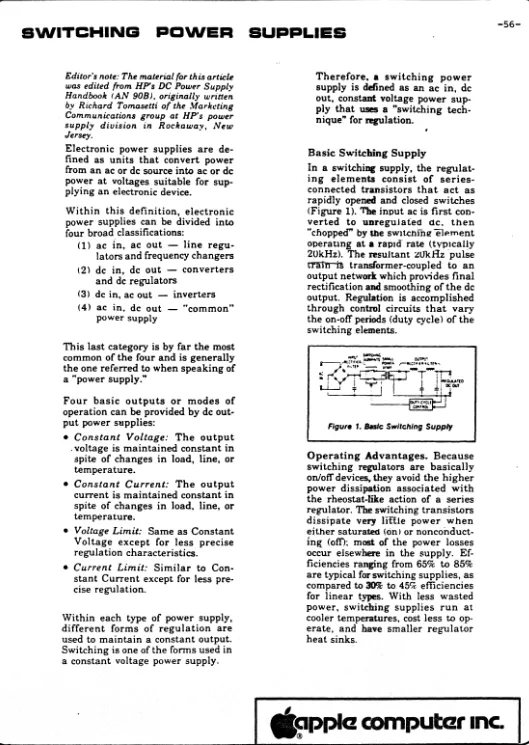
3.0 SWITCHING POWER SUPPLIES
---Thoa- basic scho:-matic diagl~aril of a S .... 'itch Mode Po~~e-r Supply is shown in Figur~ 4.
The rnode of op~ration of this pOI,l.ler supply is as
follow·s:-
-39-The AC input from the line- is rectified and filtered to obtain a DC voltage that has an acceptabl~ ripple content.
The transistor switch chops the DC voltage into a series of
rectangular waves which are changed to the roa-quired voltage by a transformer. The voltage appearing on the secondary of this
transformer is rectified and filtered to produce the final output voltage(s) required.
In order to ensure that the output voltage stays wthin the rE'qui red t 01 erar'lces, a modu I at i on can t I~O I c ir"'cu it sel"'lses the ouiput voltage and compares it with a reference voltage. The resul tant di fference h'om this cornparism is used to adJust the
ON/OFf
ratiO of the rectangular ·waveform. The variation off thisON/OFF
ratio determines the amount of energy that is transferredfrom the primary store to the secondary store(s).
It is in this way that a Switching Power Supply is abA. to respond to varyinq load demands wi.thout having to dissipate a
sur~lus of power as heat.
ItJPu-r
LINE.
...
~~--nANSfo~E.~
RW.t1
-- !
t
~
-I
~F\<'P.
,
_
...
eowet1l!(.
~..
,\
JtI\..
l~E
H
FtW·M-~A~
~
:
b~~E
~D\J.J;l"o~,\
REF.
FIC:a.4·
B"s\c. S,,",PS P'A~~AM
DC... otrfp,,.f
FIL~
0
• J
I
~
o
4.0 ADVANTAGES
&
DISADVANTAGES OF S.M.P.S.
The basic re-qLlil~o:-r;lel1ts of micropl~oC:~!5Sor based e-qLliprllo:-nt .and othe-r associ.at~d appl ications fOl"' Jl9IlIIe-r sUDpl ie-s
al~o:-:-- the power supply must produce all the required yoltaoes / currents within the pr'oscr ibedto leranco:-s
-
the power supply must be as sma It as practical-
the pow.:-\"' supply must u1e-i gh a little aspossible--
the power supply must be as reI i_Ie as possible and pl~oducel i t t l e heat as possible
-
the power SLIPP I Y must conform toi:r
meet a I I the mandatory International standards that relat~ to Safety and Interfere-neeADVANTAGES
Ef f ic iency
In a linear regulating supply .thepower losses al~e vel"y high. This is due to the continuous operawion of the series pass regulating device. ~onsequentlYI the pOIJ.1er efficiency is poor -ranging from 1(11 to 40%, the average- being around 30X.
This figul"e of 30X means that of the total power put into the power supply only about 30% of i t ql!'ts to the load - the
rerri~ining 70X is dissipated in the linear powe-r supply as heat.
-41-as
In a Switch Mode Power Supply the device that acts as the regulating switch (usually a power tran5isto,") is opel"ated in either a fully saturated state or is completely turned off. Since
the ON and OFF states are the onesDf minimum po~~er dissipation the power efficiency of a SMPS is fJUCh higher and ranges from
651
to
SOX
or more.
-42-Figur.5 illustrates the comparism betwe.n the power efficiencies
of lin.ar and SMPS.
f~
~701c
F,G.. 5
5
EFF\C ..
\E~j c.of.{P-Ae.l~
H
~
P
L
S
IN
-'"
This can also
beillustrated by looking at a typical power
supply.
For
example:-For a
Pow~rOutput of
125 Watts
Linear power consumption
232 Watts
SMPS
power consumption
54 Watts
Power saved
178 Watts
Linear supplies taKing pow.r from
th~mains supply worK at 50Hz
(or 60Hz). Since isolation
b~tweenthe input and output is ne.ded
a transformer is r.quired. The low worKing frequency dictates
that the transformer core must
beof silicon
ste-~lwhich in turn
results in a cOffiponent that is both big and h.avy.
SMPS operate at much
high~r fl"'equenci~s-
typically about
25
,000Hz. This
m~ansthat the transformer can use
f~rriteIllaterials which are both smaller and
Iighter than si
1iam st.el.
An extra
benefit is that the efficier"lcy of ferri t . in terms of
magnetic saturation is better
t~ansilicon steel which .eans that
the pOI.uer losses through thllt transforrr,er are lo,,'er for SMPS than
for linear supplies.
A further benefit of using high frequency switching that
contributes to
th~reduction of size and
w~ightis that the
s~condary
electrolytic capacitol"'S can
bemuch smaller. For linear
supplies it is COR)mOn to
see filter capacitors of 40,000 uF being
used. SMPS can use
1 / 000uF
c~pacitors.These size and weight adval1taqes can be
summcu"'is~das
follo,,",s:-.
Using the example of a
125Watt power supply.
Linear
SMPSVolume comparism
4cu in/W
1cu in/W
Area reduction ratio
3.3
1Weight reduc
tion ra t io
5 1
Lin~ar suppli~s
tend to
hav~ r~strictedinput
voltag~ranges.
Often multi-tapped
transform~rsare used. This
requir~s th~equipm~nt
end user to set
th~ corr~ct voltag~tap according to
wh~re
the equipment is to
b~ us~d.
-44-SMPS have very wide
op~ratingvoltage
rang~s.Providing
th~SMPS
is designed to use primary capacitors sufficient to store the
energy required even when fed from
th~low limit of input voltage
the power supply will continue to function correctly. This is
because
unliK~the linear supply the SMPS is not concerned with
primary volts but only with the .nergy source.
The typical
op~ratingrange of ASTEC SMPS, when set for nominal
230 V input,
i~from 180 V to 265 V without
needto
chang~'anyinput voltage $elector. A comparable range for the nominal 117 V
setting is also obtained. The change over from nominal 230 V to
nominal 117 V input setting is achieved by simple alTering the
input rectifier circuit from that of a simple bridge (on 230 V)
to a voltage doubler (on 117 V) • Thus the resultat DC that is
used by the switching transistor remains the same for both" input
vol·tage ranges.
DISADVANTAGES
Noise
We have to accept that SMPS can produce more radiated and/or line
conducted
nois~than linear supplies.
Careful design by ASTEC does
r~duceboth radiated and line
conducted noise to acceptable amounts.
Special
d~siqnfeatures
are:-Use of special input filters in series with the
I in~.
These arJ!?carefully balanced to obtain the rlla"X.iruUffl
r~Jection
of
th~switching frequency and its
har~onics.Pi section filters on
th~outputs.
Use of a copper
5hiel~ b~tw~enthe primary and
secondary of the
powertransformer. This acts as an electrostatic
shield as
iiiconne-cted to the safety ground of the power supply.
Correct and balanced layout of critical conductors
on the PCB to ensure- that fields cancel.
Use of another copper shield wound over the
secondary windings of the power transformer to reduce magnetic
l~ad i a t
ion.
As stated earlier, ASTEC Switching Power Supplies do meet the
International Standards for both radiated and line conducte-d
noise. The lI'Iost widely spe-cified standards are the- VDE0875 and
VDE0871 and CISPR 1 and 3.
Transient Response
Note:- Transient response is the- time re-quired for the- output
voltage tore-turn to within the specified re-gulation limits when
the-re is an abrupt change on either the load or the line.
for a conventional linear regulator the figures would be of the
orde-r of
10's
of microsec·onds.
for a SMPS these figure are around 10's of mi
I Ii seconds.
These- times result from the system used and are a funct ion of
the-swif~hing
frequency -
eventually if
we
can increase the switching
frequency sufficiently ( to 10
MHz)
the-n the response time will
come down.
Meanwhile, in most practical systems
we can live with
the Transient Response times
we get.
SUM:1ARY
The
Advantag~~of the SMPS in terms of Size, Weight, Efficiency
and
ReIiabi
1 ity more than
corup~nsatefor the disadvanta.ges.
5.0 TYPES OF SMPS
Th~r~
are a number of different ways that a SMPS can be desiqned.
Ther~
are
two main
variants:-FlybacK Converters
Fe~d
Forward Converters
The range of SMPS that ASTEC manufactures ,,·,ainly use Flyback
t~chniques. Th~
Flyback converter is very suitable for power
suppli~s
up to about 1S0 Watts.
Abov~this power the
F~~dForward
typ~s
tend to predominate. ASTEC make both types but by virtue of
th~
nWf,ber of power suppl ies in the
SCI -100 Wat t rangE- that
webui ld the Flyback is
th~most common circuit soll..Ition in our
current production.
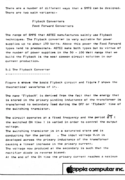
[image:53.624.57.568.56.792.2]5.1 The Flyback Converter
Figure
bshows the basic Flyback circuit and figure 7 shows
thE-theorectical waveforms of it •.
The name 'FlybacK'. is derived from the fact that the
enel~gythat
is stored in the primary winding inductance of the transformer is
transferred to
s~condaryload during the OFF or 'Flyback' time of
the switching transistor.
The circuit operates at a
fi~ed
frequency and the period
~
(
the switched ON time) is varied in ol-der to control the output
vol tage.
The switching transistor is in a saturated state and is
conducting for
th~ p~riod• The input voltagE- V.in is
developed acros& the primary
inductanc~of the
transform~rcausing a linear increase in the primary current.
Th~
voltage now produced at the secondary is such that
thE-rectifier diode is reverse biased.
At the end of the ON t irne the prirllary current
r~achesa maxirl)urn
~'--0--c
'
LIN~
, NP\l-r
. FlG..
b .
P.W·M
Jo-o-'j.c.-f\....
CI~1'1"
SAS\c- . F'L'IBAC..K
CI~C.'lI-r
-47-v.,f\, --
-
-
-ov
valu~ 12 aft~r which It fal Is to zero.
1..
where 1.. is th~ primary inctuctanc~.
Th. energy stored in th~ primary inductance
is:-2
L.1
2
Th. stored energy per cycl.
W
is givenby:-Dr
w •
( V. in. &T)2
W • L (---)
- ( L 2
2
2
V. in •
ST.
21..Hence the output power available
=
energy in Joules x switchinq fr~quency
Therefore:-2
2
V.
in.ST
Output Power· ---21..
As the primary curr~nt falls to zero the voltage across the transistor increases from that of its saturation to a positive value that is in excess of 1hat of the supply.voltage V.in. A
capaci'iv~
networK 1S connected across the trans1stor to limit
-49-th~
rate of rise of thlS voltage.
When the vol tag+ aCl"'OSS thoe tl"'ansis·tor e'X.ce.."ds V. il"l, the
transformer primary is reversed and reverses the
s~condaryvol tage thus causing the output rect
iHer diode to cond\.lct.
An energy recovery winding and a diode limits the voltage across
the switching transistor and returns the energy stored in this
inductance to the supply when the circuit is operated without a
load on the secondary. This winding is bifilar wound with the
primary in order to minimise the leakage inductance
b~tweenthese
windings.
In
summary:-First: Transistor conducts for a period (t.on)
Energy is taken from the input and stored in the inductor.
Second: Durinq remainder of period (t.off) the output diode
conducts and the energy stored in the inductor is transferred to
t he au t pu: t •
The output voltage is dependent on the input voltage and the
conduction period of the transistor.
To stabilise th. output voltage the control
circuit.~eterminesa
value for the period
the loading.
appropriate to the input voltage and to
5.2 The Feed Forward Converter
Fiqure
a
shows the basic circuit.
The operation of the Feed Forward converter is oppostte to that
of the FlybacK conv.rter.
In the Flyback energy is transferred frOf,. primary to secondary
during
th~OFF
stat~of
th~SWllchlng tranSlstor.
In
1h~ f~.dForward en.rgy is transferred during the ON state.
Th~
smoothing inductor
Ll in
s~ries with the rectifier diod~ 01provides a voltage that is proportional to the lransistor ON
1ime.
Th~ diod~02 provides the path for the output current when
the transistor is not conduct ing. Wheol' the transistDr is OFF the
transforfller magnet izing
curr~I'tis
return~dto the- supply by an
energy recovery winding in a similar mode to that of the Flyback
cOl1ver t er.
-50~
6.0 DATA SHEETS AND SPECIFICATIONS
---Our Data Shll?ets [10 contain tho: anSI..I,Ill?rs to most qUll?st ions put by
potential customers. The purpose of these fll?w notes is to explain how to find those answers.
We have recently started to introduce tho: 'NeowlooK' [lata Sh .. ets. We wil I use one of thesll? (AC9231) as an example,
Front page - the side with the photo
Between the heavy red lines you will find the basic Volts and
Amps
PL.US
any special features that the supply has. For example, the AC9231 has the 'negative' outputs floating. This means these can have ei ther terrninal tied to ground or to another output. The output described as '-12V' could be stacKed on top of the +12V output to
get a +24V output that would then have a current. ratinq of 0.5 Amp which is the lower of the-two 12V outputs current ratings.
The rest of the front page is devoted to the mechanical
dimensions and pin connec,t ions. Note tha t we ar"e get ting bet ter
and giving such details as the mating connector details.
NO"· - WE DO NOT SUPPLY THE MAT I NG PARTS
Unless we state otherwise, the power supply IfIay be mounted in any plane. The photo, apart from being pretty is there so that
engineers can
see
the internal layout and hence deduce where the hot-spots will be.The- hea t produc i ng i t eros are t he power trans i s t or, se-condary diodes, tran~former and ripple capacitors.
Again unless otherwise stated on the Data Sheet
we
do not e~pectthe custom'?r to provide any e~tra cooling for the power supply -normal convection and radiation cooling up to the rated: ambient
computczr Inc.
-51-(usually 50 deq. C ) is adequate.
Back Page.
From the top of the page to the first heavy red line we show the
main Volt/Amp load data and the line input limits.
Input Voltage:- The min and max figures are those between which
the power supply will stay within the specified output volts for
all specified output loads. The 9231 will
~ontinueto work with
inputs lower than lS0V -
in fact it continues down to around lSOV
but
we don't spec it down to that level. Above 270V we have a
margin for short duration operation -
line spikes and such like
-but not for sustained use. Nowhere in Europe can you find·mains
supplies that
exceed 270 Volts.
Input Frequency:- We test the supply over th. specified range. In
fact since the input circuit is only a
r~ctifierand capacitor it
is obvious that
th~supply can accept a much wider range of input
frequencies should anyone come up with that
requir~ment.Outputs:- The min and max voltage of each output is specified as
is the min and max load. rhe
twospecs have to be read
togeth~r.For the 9231 +SV output, it means that the volts stay between 4.9
and 5.1 over the load
curr~ntrange from 6.0 Amps to 1.2 Amps
-.again for any value of line input volts within that spec.
The minimum load specified may not
bethe minimum load 'the power
supply needs to keep worKing BUT it is the minimum that we
gaurantee the spec to hold.
NOTE:- The
new
family of SMPS have a much better control window
than the earlier types. This means that the 2SX minimum load
requirement has
qon~and also it means that the problems of
tracKing
betw~~none output and another are very much less.
In
betw~enthe two heavy red
lin~sare the remainder of the
.l~ctrical
specifications and notes.
-52-I.
Effici~ncy:-
This is
p~rc.ntag~of
th~input
pow~rthat can
b~d~liver~d
to
th~load. It will vary with
th~load. Mostly
th~SMPS wil
I b~at its most
.ffici~nt wh~nd.liv.ring
th~maximum
pow~r.
The figure specifi.d is a minimum -
the real typicals are
nearer to 70X and some units
0as high as 75X.
-53-Operating Temp:- When
we say 'Ambient'
<