Deposition of Metallic Coatings on Polymer Surfaces using
1Cold Spray
R. Lupoi and W. O’ NeillInstitute for Manufacturing, Department of Engineering, University of Cambridge 17 Charles Babbage Road, Cambridge, CB3 0FS, UK
Corresponding author is R. Lupoi e-mail: rl372@cam.ac.uk
phone: (+44)01223764617 fax: (+44)01223464217
ABSTRACT
Current coating technologies such as plasma spray, High Velocity Oxy Fuel (HVOF) or laser cladding involve the delivery of molten materials during the deposition process. However, such processes are not well suited to the deposition of metallic coatings on polymers and composites. 1Cold Spray (CS) has attracted much industrial interest over the past two decades. In this method, a material in powder form is accelerated on passage through a converging-diverging nozzle to high speeds via a high pressure coaxial carrier gas jet. The high impact kinetic energy deforms the particles, which creates effective bonding to the
substrate.
This paper presents the results of an initial study on the potential of the 1CS process to produce metallic coatings on non-metallic surfaces such as polymers and composites for engineering applications. Experimental and Computational Fluid Dynamics (CFD) results when spraying copper, aluminium and tin powder on a range of substrates such as PC/ABS, polyamide-6, polypropylene, polystyrene and a fibre-glass composite material are presented and analyzed.
1-INTRODUCTION
Bray et al. have further improved the process by adding thermal energy to the deposition zone with the use a laser source, in such a way to reduce particle yield stresses, facilitate greater bond strengths and promote higher coating densities for lower particle kinetic energies [11].
Of particular interest for engineering applications are metallic coatings on surfaces such as plastics, fabrics or composite materials. The nature of such substrate makes the process of metal deposition particularly difficult. Successful coatings have been achieved with thermal spray through complete melting of the feedstock material. As an example,5 Voyer et al. have successfully managed to deposit aluminium on fabric materials by using flame spray [12]. It was possible to achieve coating conductivity, despite the high level of internal porosity. Also, in this case it was necessary to incorporate in the system a cooling apparatus, to protect the fabric material from the high temperature molten sprayed metal. Spraying without cooling system was only possible at standoff distances in excess of 250mm, resulting in low deposition efficiencies. Nevertheless, the increasing demand for low energy, environmental friendly, efficient and low-cost processes is driving away research from current methods to alternative techniques such as Cold Spray (CS).
There are few reports of the application of CS in the production of metallic coatings on polymer substrates. Zhang et al. [13] have investigated the effect of substrate type when spraying aluminium powder (99.9wt%, average size = 25m). The range of materials
included ABS and glass. Results have shown that deposits on non-metallic surfaces were thin and not continuous; only relatively small particles (<5m) were adhered and heavy erosion of
the plastic substrate was observed. Lee et al. [14, 15] suggested that mixing the feedstock powder with ceramic material such as Al2O3 may facilitate the deposition of metals onto hard
On the other hand, Sturgeon et al. [16] have successfully formed aluminium coatings of about 600m thickness on Carbon Fibre Reinforced Polymer (CFRP) surfaces. In this case, helium
was used as carrier gas, heated up to a temperature of 3000 C. A De-Laval converging-diverging nozzle geometry was utilized, with an inlet pressure of 20bar. Results showed good deposition characteristics, although the authors noted that the types of reinforced polymers on which metal deposition was achievable required further studies.
This paper further investigates the use of the CS process to form metallic coatings on polymer surfaces. Metals of general engineering interest such as copper, aluminium and tin have been sprayed onto substrates including a commercial blend of polycarbonate and ABS (PC/ABS),
polystyrene, polyamide-6, polypropylene and a glass fibre composite material.
2- 1CS APPLICATION TO NON-METALLIC SUBSTRATES
An in-house Cold Spray facility developed at the University of Cambridge was used for experimental testing. The CS system is shown in Figure 1.
Figure 1
A nitrogen gas source of maximum pressure 30bar is fed through a converging-diverging nozzle. 2The system does not incorporate a gas-heater, therefore spraying is carried out at room temperature. The nozzles are typically made out of tool steel, with a variable diverging
the substrate to form the coating. However, the maximum achievable velocity is dependent on the powder material and size.
Figure 2 Figure 3 Figure 4
Powders materials and geometries typically used in engineering applications were tested in theses initial trials. Specifically, Figure 2, 3 and 4 show Scanning Electron Microscope (SEM) images of the powder feedstock used, i.e. commercial aluminium, copper and tin. The aluminium was acquired from the Aluminium Powder Company Ltd., -53+10m size
distribution. On the other hand, the copper (HC Cu) and tin (SC10) powders are from Sandvik Ospray Ltd., characterized by -32+10m size distribution. The aluminium powder was
produced by the water atomization process, therefore it exhibited irregular prismatic geometries; on the other hand the copper and tin particles were gas atomized giving a more regular and spherical shape.
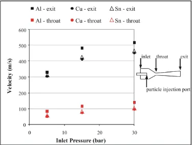
In order to study the effect of powder impact speed on deposition characteristics, the nozzle inlet pressure was varied across the range 5-30bar. As an example of such relationship, Figure 5 shows the calculated centreline velocity magnitude of a spherical particle (20m diameter)
elements of nearly 20000. The “high-mach-number” drag law algorithm was used in this case
[17], suitable for spherical high speed particles. Pressure-inlet and pressure-outlet boundary
conditions were set at the inlet and outlet surfaces of the computational domain, and the k-
realizable turbulence model was used.The simulations were converged up to the second order
discretization scheme, by following the density-based solver algorithm. The graph in the figure shows the calculated speeds at the nozzle throat and exit, for 20 m diameter particles
of aluminium, copper and tin. It can be appreciated that at increasing values of inlet pressure the speed of the particles within the nozzle grows. Also when spraying at the pressure of 30bar the particle velocity raises of about double than the value at 5bar nearby the throat, and increases of approximately 50% at the exit of the nozzle. In addition, aluminium is shown to travel faster in comparison to copper and tin, due to its low specific weight.
Developed commercial CFD packages are nowadays valuable instruments to predict particles
and flow characteristics in cold spray applications. Nickel et al. [18] have implemented Fluent
to model supersonic flow over a shock tube spraying device, and also used the
“high-mach-number” algorithm to model the particles drag law. On the other hand, Bray et al. [11] have
extensively compared metallic particle velocities by a CFD analysis with Fluent against
experimental measurements. Despite commercial powders may not be regarded as perfectly
spherical, it was observed that computational and experimental results were in close
agreement (<5%) at both low and higher nozzle inlet pressures.
3.2-Spray trials
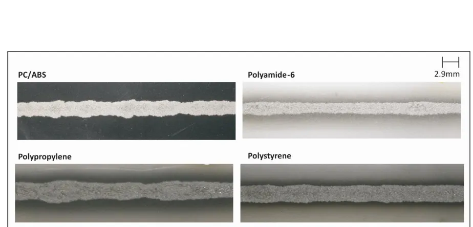
Experiments were carried out in order to identify best process parameters setting, on untreated commercial polycarbonate-ABS blend (PC/ABS - Cycoloy C1100HF), polystyrene (Nova 124N), polyamide-6 (DSM Akulon F136-C1), polypropylene (Basell Moplen HP561R) and a glass-fibre composite material. Figure 6 shows a close up picture of coatings obtained at 5bar and 30bar nozzle inlet pressure when spraying copper powder onto PC/ABS and the glass-fibre reinforced composite material. The supersonic nozzle used in this case was characterized by an internal De-Laval profile with a diverging section length of 180mm. The 5bar coating on PC/ABS, shown in Figure 6a, was obtained with a distance nozzle exit – substrate, the Standoff distance SoD, of 40mm, substrate transverse speed of 8.3mm/s and by imposing a rotational speed of 15rpm to the powder feeder wheel. On the other hand, the optimum operational settings for the 5bar coating on the composite material (Figure 6b) were same as above, but a visible coating could only be observed at lower powder flow rates, i.e. with 5rpm wheel speed. Results from Figure 6a and 6b shows that a relatively thin layer of metal can be deposited on the surface at the imposed process conditions. On the other hand, Figure 6c shows an example of a 30bar coating on PC/ABS, produced with a SoD of 40mm, transverse speed of 16.6mm/s and a feeder speed of 18rpm. The 30bar coating on the composite material is shown in Figure 6d, obtained with 40mm SoD, transverse speed of 8.3mm/s and 12rpm feeder speed. For these last two cases, the change of the parameters settings (at the fixed inlet pressure of 30bar) resulted in very small variations to the tracks shown in Figure 6c and 6d, however the best observable results were obtained with the settings presented in this paper.
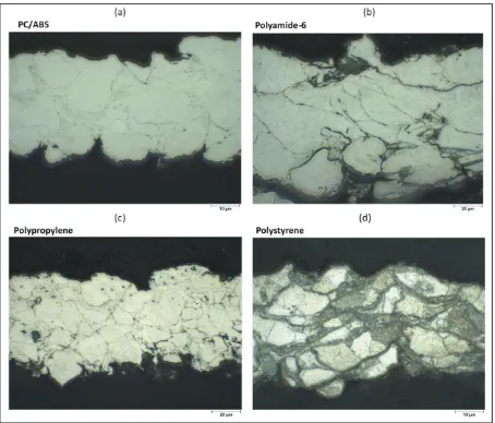
cross-sectional profiles, where the substrate material is below the coating. At small inlet pressures, i.e. when low energy impacts occurs, a first layer of particles embeds below the surface, as shown in Figure 7a and 7b. Powder material impacting on top of this first layer does not adhere and recoils off the surface. Once the first layer is deposited, subsequent impacts do not carry sufficient energy to adhere to the lower metal layer due to their low speed. In this case the impact energy is only sufficient to penetrate the plastic surface, but not to form a solid metal-to-metal coating. Such behaviour suggests that once the metal seed layer is deposited, the deposition mechanism on subsequent layers is similar to the one observed for metallic surfaces. In fact, powder interactions with the plastic material can only occur on the first coating stratum.
Figure 6
When increasing the nozzle inlet pressure (i.e. the particles speed) in the attempt to form a solid coating, heavy erosion of the substrate occurs as shown in Figure 7c. Empty craters are clearly visible on the cross-section of the PC/ABS. In this particular case, although the particle speed is optimal for the copper to create a metal coating, the impact energy and related impact stresses transmitted from the particle to the substrate go beyond the material strength, hence heavy erosion takes place. Figure 7d shows the same effect, when using a glass-fibre reinforced composite. Despite the reinforced characteristics of this material, broken fibres are visible.
Figure 7
this case, particle impacts did not impose severe damage to the polymer surface and no deposition was achieved. This effect could be due to the relatively low density of aluminium, being incapable of generating enough impact energy with the substrate in comparison to other materials, i.e. erosion is negligible [19]. However, it was not possible to deposit aluminium in this case. A reason for this relies upon its relatively high critical velocity, in the region of 600m/s [20], which may be beyond the maximum achievable with the current cold spray
system with no gas-heating implemented.
103mm and by setting the rotational speed of the screw feeder to 200rpm. Tin deposited well at the substrate transverse speed of 14mm/s in all cases. In order to better identify the coatings characteristics, cross-sections were cut and visualized with the optical microscope and pictures shown in Figure 9. It can be clearly seen that with all substrate materials considered in this paper it was possible to achieve coatings 3in the range between 45m and 100m thickness. Deposited particles can be clearly identified in Figure 9d, as the coating in this case
was chemically etched.
Figure 8 Figure 9
Their final geometry, when compared to the initial shape, suggests that plastic deformation occurred and particles deposited one on top of the other to form a multi-layer coating geometry. These type of coatings had shown good 5electrical conductivity, without the necessity of any post-treatment or pre-treatment. 3Coatings thickness following one pass varied from 45m on the PC/ABS and polystyrene materials to nearly 100m on the
polymamide-6 substrate. The attempt of a second pass on top of the formed first layer of tin
resulted in the destruction of the coating in all cases. Reasons and causes for such behaviour
are currently under investigation. By using the spraying parameters as input, it was therefore
3.3-Process Characterization
Experimental results obtained with copper, aluminium and tin powders have been summarized in the chart shown in Figure 10, which describes an initial characterization of the CS process applied to polymer substrates. Results obtained with copper had shown heavy erosion of the substrate, while aluminium only produced slight surface erosion but no deposition. On the other hand, tin has performed well and coatings were achieved on a variety of plastics over a range of parameters. As a consequence, the chart in Figure 10 has been divided into sections, each of them describing the probable deposition behaviour for the correspondent powder type. In this initial characterization chart, the zones boundaries are for simplicity straight lines. The chart reports the powder material, against the correspondent impact energy of particles travelling at optimum deposition speed. Values for the deposition/critical velocity of different materials and particle sizes can be calculated by the theoretical approach given by Schmidt [20]. For this case, a 25m particle diameter was
assumed, and the average velocity within the deposition window was selected for each material.
Dense and relatively strong particle materials, such as copper, can generate single energy impacts E of nearly 0.02mJ (E=1/2mv 2), where m is the particle mass and v is the deposition
velocity. As particle sizes are in the order of microns for cold spray applications, this level of impact energy can result in severe contact stresses; therefore erosion of the polymer substrate is in all probability to occur. On the other hand, for lower strength metals such as tin, the critical velocity is most likely to diminish; therefore the impact energy transmitted on the substrate can dramatically decrease and deposition becomes achievable. It can be appreciated from Figure 10, that a particle of copper can generate about 10.7 times more energy at impact
5
than tin. In contrast, light materials (such as aluminium), characterized by both low density
impact energy is relatively low, however deposition may be accomplished only with more
complex and costly systems capable of accelerating particles up to their critical velocity
magnitudes, such as with gas-heating or Helium cold spray. A prediction of the behaviour of other metals, based upon the experimental results with aluminium, copper and tin powders, is included in Figure 10. Particles of stainless steel 316L would generate higher impact energy
5
than copper, therefore erosion of the polymer substrate is in all probability to be
predominant. Despite its high density, lead (Pb) would only produce relatively low levels of impact energy resulting in possible deposition. On the other hand, titanium (Ti) places himself on the boundary within the transition window alongside aluminium. For these cases erosion may be negligible, however the critical velocity is high.
Figure 10
4-CONCLUSIONS
1
copper travelling at deposition velocities, can generate single particle impact energies in the order of 0.02mJ. This leads to severe contact stresses, therefore the predominant effect is erosion of the polymer. Aluminium, due to its low specific weight, does not bring any considerable damage to the surface; however its critical velocity could not be achieved with the cold spray system used in the experiments. On the other hand, it was possible to adjust the spraying parameters and select a suitable nozzle type to obtain coatings of tin on a variety of plastic substrate materials. 3The coating thickness was measured to be in the region between 45m and nearly 100m, while the average critical velocity was estimated throughout a CFD
analysis to be 310m/s. The theoretical impact energy of tin powder was calculated to be 10.7 times lower 5than copper, resulting in negligible erosion. No surface pre-treatment was applied prior the spraying procedure, also coatings have shown good electrical conductivity. A process characterization chart has been therefore initialized, showing the relationship between properties of feedstock powders against deposition behaviour. By analyzing experimental results with aluminium, copper and tin, it was predicted that stainless steel 316L
would cause erosion such as copper. On the other hand, titanium would perform similar to aluminium, and lead is most likely to successfully deposit.
ACKNOWLEGMENTS
REFERENCES
[1] L. Pawlowski, “The science and engineering of thermal spray coatings”, Wiley, 2008.
[2] S. Deshpande, A. Kulkarni, S. Sampath, H. Herman, “Application of image analysis for characterization of porosity in thermal spray coatings and correlation with small angle neutron scattering”, Surface & Coatings Technology, 187 (2004), 6-16.
[3] M.P. Planche, H. Liao, C. Coddet “Oxidation control in atmospheric plasma spraying coating”, Surface & Coatings Technology, 202 (2007), 69-76.
[4] V.V. Sobolev, J.Gilemany, J.M. Gilemany “HVOF spraying: theory and applications”, The Institute of Materials, 1997.
[5] V.K. Champagne, “The cold spray material deposition process: fundamentals and applications”, Woodhead Publishing Limited, 2007.
[6] Hong-Ren Wang, Bao-Rong Hou, Jun Wang, Qi Wang, and Wen-Ya Li, “Effect of process conditions on microstructure and corrosion resistance of cold-sprayed Ti Coatings”, Journal of Thermal Spray Technology, Volume 17 (5-6), 2008, 736-741.
[7] E. Sansoucy, G.E. Kim, A.L. Moran, and B. Jodoin, “Mechanical characteristics of Al-Co-Ce coatings produced by the Cold Spray Process”, Journal of Thermal Spray Technology, Volume 16 (5-6), 2007, 651-660.
[8] T. Marrocco, D.G. McCartney, P.H. Shipway, and A.J. Sturgeon, “Production of Titanium Deposits by Cold-Gas Dynamic Spray: Numerical Modeling and Experimental Characterization”, Journal of Thermal Spray Technology, Volume 15 (2), 2006, 263-272.
[9] G. Bae, S. Kumar, Sanghoon Yoon, Kicheol Kang, Hyuntaek Na, Hyung-Jun Kim, Changhee Lee, “Bonding features and associated mechanisms in kinetic sprayed titanium coatings”, Acta Materialia, 57 (2009), 5654–5666.
[10] Y. Xu, I.M. Hutchings, “Cold spray deposition of thermoplastic powder”, Surface & Coatings Technology, 201 (2006), 3044–3050.
[12] Joel Voyer, Peter Schulz, and Martha Schreiber, “Electrically conductive flame sprayed aluminum coatings on textile substrates”, Journal of Thermal Spray Technology, Volume 17 (5-6), 2008, 818-823.
[13] D. Zhang, P.H. Shipway, and D.G. McCartney, “Cold Gas Dynamic Spraying of
Aluminum: The Role of Substrate Characteristics in Deposit Formation”, Journal of Thermal Spray Technology, 14(1), March 2005, 109.
[14] Ha Yong Lee, Se Hun Jung, Soo Yong Lee, Young Ho You, Kyung Hyun Ko, “Correlation between Al2O3 particles and interface of Al– Al2O3 coatings by cold spray”,
Applied Surface Science, 252 (2005), 1891–1898.
[15] Ha Yong Lee, Young Ho Yu, Young Cheol Lee, Young Pyo Hong, and Kyung Hyun Ko, “Cold Spray of SiC and Al2O3 with soft metal incorporation: A Technical Contribution”,
Journal of Thermal Spray Technology, Volume 13(2), June 2004, 184-189.
[16] A. Sturgeon, B. Dunn, S. Celotto, W.O’Neill, “Cold sprayed coatings for polymer composite substrate” European Space Agency, (Special Publication), ESA SP, n616, September 2006.
[17] Fluent 6.3.26 User Guide.
[18] R. Nickel, K. Bobzin, E. Lugscheider, D. Parkot, W. Varava, H. Olivier, X. Luo, “Numerical Studies of the Application of Shock Tube Technology for Cold Gas Dynamic Spray Process”, Journal of Thermal Spray Technology, Volume 16 (5-6), 2005, 729-735.
[19] J. Vlcek, L. Gimeno, H. Huber, and E. Lugscheider, “A systematic approach to material eligibility for the Cold-Spray Process”, Journal of Thermal Spray Technology, Volume 14 (1), 2005, 125-133.
[20] Tobias Schmidt, Hamid Assadi, Frank Gartner, Horst Richter, Thorsten Stoltenhoff, Heinrich Kreye, Thomas Klassen, “From Particle Acceleration to Impact and Bonding in Cold Spraying”, Journal of Thermal Spray Technology, 18(5-6), Mid-December 2009, 794-808.
LIST OF FIGURE CAPTIONS
Figure 1: The 1Cold Spray (CS) system. Figure 2: SEM image of aluminium powder. Figure 3: SEM picture of copper powder. Figure 4: SEM picture of tin powder.
Figure 5: Computed particle speed (20m diameter) at nozzle exit and throat for 5,15,30bar nozzle inlet pressure with nitrogen.
Figure 6: Close up pictures of copper tracks. (a), (b) on PC/ABS and glass-fibre reinforced composite with 5bar inlet pressure. (c), (d) 30bar inlet pressure.
Figure 7: Micrographs of track cross-section when spraying copper powder. (a),(b) low speed 5bar nozzle inlet pressure onto PC/ABS and glass-fibre reinforced composite. (c), (d) high speed 30 bar inlet pressure onto PC/ABS and glass-fibre reinforced composite.
Figure 8: Tin tracks on various polymer substrates.
FIGURES
Figure 1 (modified according to Reviewer 2)
[image:17.595.86.449.86.334.2]Figure 3
Figure 7
[image:21.595.78.540.504.726.2]4