Figure 4 A liquid membrane device for sample preparation. A, hollow fibre (reaching through a hole drilled through the whole block); B, fused silica capillaries inserted in the ends of the fibre; C, O-rings for fixing the fibre and capillaries; D, connectors for the donor channel. (Reprinted with permission from Thordarson E, Palmarsdottir S, Mathiasson L and Jonsson JA (1996) Sample preparation using a miniaturized supported liquid membrane de-vice connected on-line to packed capillary liquid chromato-graphy.Analytical Chemistry 68: 2559}2563.)
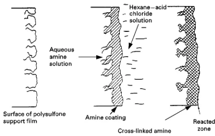
Figure 1 Schematic of the interfacial polymerization procedure. (From Cadotte JE and Petersen RJ (1981) Thin-film composite reverse osmosis membranes: origin, development and recent advances. In Turbak AF (ed.) ACS Symposium Series 153, Washington, DC, pp. 305}326.
employed for the analysis of drugs in a matrix of blood plasma.
See also: III/Membrane Preparation: Interfacial Com-posite Membranes; Phase Inversion Membranes.
Further Reading
Degn H (1992) Membrane inlet mass spectrometry in pure
and applied microbiology. Journal of Microbiological
Methods15: 185.
Gabelman A and Hwang ST (1999) Hollow Rbre
mem-brane contactors.Journal of Membrane Science159: 61.
Giddings JC (1991)UniTed Separation Science. New York:
Wiley.
McKinney R (1987) A practical approach to the
prepara-tion of hollowRbre membranes.Desalination62: 37.
Mulder M (1991)Basic Principles of Membrane
Techno-logy. Dordrecht: Kluwer.
Roper DK and Lightfoot EN (1995) Separation of
bio-molecules using adsorptive membranes. Journal of
Chromatography A702: 3.
Sastre AM, Kumar A, Shukla JP and Singh RK (1998) Improved techniques in liquid membrane separations:
an overview.Separation and PuriTcation Methods27:
213.
Tsapatsis M and Gavalas GR (1999) Synthesis of porous
inorganic membranes.MRS Bulletin24: 30.
van de Merbel NC (1999) Membrane-based sample preparation coupled on-line to chromatography or
electrophoresis. Journal of Chromatography A 856:
55.
Interfacial Composite Membranes
J. E. Tomaschke, Hydranautics Oceanside, CA, USA
Copyright^ 2000 Academic Press
Introduction
The development of asymmetric cellulose acetate membranes in the 1960s was a breakthrough in mem-brane technology. These memmem-branes consisted of a thin surface skin layer on a microporous support. The skin layer performed the separation required and because it was very thinSuxes were high. The micro-porous support provides the mechanical strength re-quired. Following these developments Rozellet al. in 1967 described the preparation of theRrst interfacial (IFC) composite membranes. These membranes have since become the standard for reverse osmosis (RO) and nanoRltration (NF) applications.
IFC membranes have the same asymmetric status of the Rrst-generation cellulose acetate membranes but are made by a very different procedure, shown schematically in Figure 1. In a Rrst step a microporous polysulfone support membrane is im-pregnated with an aqueous solution containing a multifunctional amine. The impregnated membrane
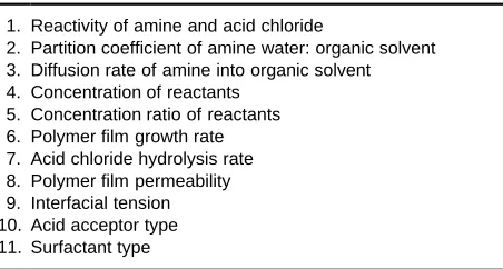
[image:1.568.294.513.513.652.2]Table 1 Interfacial polycondensation variables 1. Reactivity of amine and acid chloride
2. Partition coefficient of amine water: organic solvent 3. Diffusion rate of amine into organic solvent 4. Concentration of reactants
5. Concentration ratio of reactants 6. Polymer film growth rate 7. Acid chloride hydrolysis rate 8. Polymer film permeability 9. Interfacial tension 10. Acid acceptor type 11. Surfactant type IFC membrane development can be divided into
two time periods. The earlier development from 1967 to approximately 1980 was characterized by work funded through the US Department of the Interior, whereas the majority of the development since 1980 has been industry funded. The early membrane prep-arations experienced a transition from the use of polymeric to monomeric amine reactants resulting in more durable products. Today the state-of-the-art IFC membrane chemistry consists of cross-linked aro-matic polyamides derived from monomeric reactants. A review by Cadotte of composite RO membranes gives an account of the evolution of developments leading up to the commercialization of high perfor-mance membranes.
The basic interfacial method of membrane prepara-tion using porous support has changed little since its inception though improvements in reactant chemistry and processing conditions have been made. The la-boratory-scale preparation method remains a valu-able intiation step in the development of IFC mem-branes because of its efRciency and simplicity. This method will be given a detailed discussion in the sections which follow.
Interfacial Polycondensation
Early Thin Film Synthesis
The origins of interfacial polycondensation reactions can be traced to Morgan of Du Pont who studied the interfacial polymerization of numerous polyamides and polyesters. He found the Schotten}Bauman reaction of diamines with acid chlorides to be an effective laboratory process, which was termed interfacial polycondensation. In this process, the irre-versible polymerization of two highly reactive mono-mers takes place near the interface of the two phases of nonmiscible liquids, as demonstrated by the model system hexamethylenediamine sodium hydroxide} water/sebacoyl chloride}hydrocarbon solvent to pro-duce Nylon 610. This model system is the basis for the discussion which follows.
When the two liquid phases containing diamine and acid chloride are brought together and the hydrocar-bon or halogenated solvent, etc.) solvent is a non-solvent for theRnal polymer, a thinRlm of the polymer will be formed rapidly at the liquid interface. Generally this polymer is found to be tough and of high relative molecular mass. In a very short time interval equiva-lent amounts of reactants combine nearly quantitat-ively, with elimination of hydrogen chloride, and pro-duce a thin Rlm. In Nylon 610 polymerization, the optimal molar ratio of diamine to diacid chloride was found to be about 6.5, indicating the rate-limiting
feature of diamine diffusion across the interface and through the growing polymer Rlm. Also note-worthy is the observation that polymer Rlm growth occurs exclusively in the organic solvent phase owing to the extremely low solubility of acid chloride react-ants in the aqueous phase. In general it is found that the mass transfer of the diamine is the rate-controlling step at all concentrations of reactants. The variables affecting interfacial polycondenzation determined from experimentation are listed inTable 1.
Mechanism of Interfacial Polycondensation
The mechanism of membrane formation has been studied using the reaction between diamines and diacid chloride and can be generalized in eqn [1]:
[1]
Normally in the interfacial polymerization, sodium hydroxide or other suitable base is added to the aque-ous phase as an acid acceptor to neutralize the hydro-gen chloride formed and drive the reaction to comple-tion. In some systems excess diamine reactant can serve as the acid acceptor since amine hydrochlorides are highly water soluble and at the same time insol-uble in hydrocarbon solvents. In addition to the simple difunctional reactants shown in eqn [1], trifunctional and combinations of di- and trifunc-tional reactants may be used to achieve the desired degree of polymer cross-linking.
described this process in eqn [2]:
dx dt"K
c
x!kx [2]
wherex is the membrane thickness;cis the concen-tration of diamine; K is the diffusion coefR c-ient of diamine through the membrane; and k is the rate constant of the inhibiting reaction (Jacid chloride hydrolysis).
When the limiting thicknessx
of theRlm is
reach-ed, dx/dt"0 and eqn [2] simpliRes tox"(Kc/k. The limiting Rlm thickness is therefore proportional to the square root of the diamine concentration. Subsequently, Enkelmann and Wegner established as a solution of eqn [2] the rate law of membrane growth:
x"x
x"[1!exp(!2kt)]
1/2 [3]
wherexis the reduced membrane thickness. Solving in terms oft(seconds) gives:
t"log(1!x) 2
!2k [4]
From this equation one can obtain values for early Rlm growth from a period of seconds to over 10 min for more complete growth. It was found from this work that the limiting Rlm thickness depended on both the absolute concentration and concentration ratio of the diamine and diacyl chloride reactants. Enkelmann also showed by X-ray diffraction techniques that in Nylon 610 membranes the polymer chains are ordered perpendicular to the interface. It was also concluded that membrane properties could be regulated by selecting particular reactive monomer ratio and concentrations, solvents and reaction times.
Early IFC Membranes
The IFC Membrane Structure
The development of IFC membranes is a logical out-come following the earlier development of asymmet-ric cellulose acetate (CA) membranes, as well as the previously discussed interfacial polycondensation work. The CA membrane is comprised of a soluble polymer or blend of polymers of varied cross-sec-tional morphology with the uppermost surface (skin) forming a permselective barrier. The IFC membrane, which is now the state-of-the art product, contains
a microporous support layer of one polymer and a separate permselective skin or thinRlm of another polymer. The advantage of the IFC membrane is that the chemistry of the all-important permselective thin-Rlm layer can be chosen independently from the underlying porous support material. Asymmetric membranes require polymers that are soluble in sol-vents necessary for the phase inversion process and this limits the number and type of polymers that can be utilized. Many useful crystalline, semicrystalline, and all cross-linked polymers are thus excluded from asymmetric membrane manufacture. The thinRlms of IFC membranes are in the range of 20}300 nm thick and when coupled with microporous supports of low hydrodynamic resistance provide membranes with unmatched productivity and solute retention.
NS-100 and PA-300 Membranes
In the discussions of IFC membranes that follow, technical milestones are highlighted with emphasis on commercially signiRcant developments. The early period of membrane development shown inTable 2 began in 1967 with the investigation of various aque-ous diamine and hexane}diacyl chloride interfacial solutions upon polysulfone porous supports by Rozelleet al. at North Star Research Institute. These Rrst IFC membranes had low salt rejections, probably due to lack ofRlm integrity since the resultant poly-mers were not cross-linked. This pioneering work, however, is signiRcant in that the essential elements for the preparation of IFC membranes were demon-strated. Shortly thereafter, in 1970, the Rrst high salt-rejecting IFC membrane, NS-100, was also de-veloped at North Star Research. This membrane was made from polyethylenimine (PEI) in the aqueous solution and toluene diisocyanate (TDI) in the hexane solution. The coated and drained polysulfone support was subsequently dried at 1103C to yield a dry composite membrane with greater than 99% salt rejection on a synthetic seawater feed at 1000 psig (6.9 MPa). A later related membrane, des-ignated NS-101, substituted isophthaloyl chloride (IPC) for TDI as the cross-linker and provided similar results. The selective layers in these membranes con-sisted of cross-linked polyurea and polyamideRlms, respectively. The membranes demonstrated high perm-selectivity but were mechanically delicate and highly vulnerable to attack by chlorine disinfectant.
Table 2 Early interfacial composite membrane developments
Date Development
1967 First IFC membranes investigated at North Star Research and Development Institute.
1970 NS-100 membrane
1975 PA-300 membrane
NS-300 membrane
Another early membrane developed from a poly-amine reactant was the PA-300 membrane by Riley et al. at UOP Fluid Systems Division in 1975. The advantage of this polyamide membrane prepared from IPC cross-linker was the lack of residual amines or amide functional groups in the polymer backbone, which exhibited improved chlorine tolerance. The performance of the PA-300 membrane was similar to that of the NS-100 and was theRrst IFC membrane to be utilized in a large-scale commercial desalination facility located in Jeddah, Saudi Arabia.
NS-300 Membrane
vulnerable amidic hydrogen. Later variants of this membrane included addition of the difunctional IPC acyl chloride, which resulted in increased salt rejec-tion and decreasedSux. As might be expected, this is probably due to the decrease in residual carboxylic acid functionality resulting from decrease of the trifunctional TMC cross-linker. Another interesting structural aspect of this polyamide is the nearly 903 out-of-plane orientation of the piperazine ring rela-tive to the aromatic ring. This rigid polymer structure containing a high volume geometry may in part ac-count for the high permeability of this membrane.
Contemporary IFC Membranes
Performance Goals
The goal of further membrane development was to maximize solvent passage while at the same time minimizing solute passage. In a typical reverse osmo-sis desalination application, this means developing membranes with high water permeability yet low salt passage. This effort applies to nanoRltration membranes as well, except in this case passage of monovalent salts and organics of low relative molecu-lar mass is preferred. Since the two performance properties of solvent Sux and solute retention are competing, it is found in practice that one generally observes a trade-off in these values with mem-brane optimization. Both the thinRlm chemistry and morphology determine its transport properties. Addi-tional goals of recent IFC membrane development include durability, chlorine and other oxidant stabil-ity, and fouling resistance.
MPD-Based Membranes
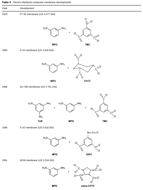
Table 3lists recent signiRcant IFC membrane devel-opments. Beginning with the wholly aromatic poly-amide FT-30 membrane developed by Cadotte at Film-Tec in 1978, it is seen that all of the subsequent membrane examples rely on the aromatic diamine monomerm-phenylene diamine (MPD). With the ex-ception of the A-15 membrane, all of the MPD-based membranes provide very high salt rejection and sim-ilar water Suxes. Consistent with the general trade-off principle, the A-15 yields higher water Sux with commensurately lower salt rejection, making it what is commonly called in the industry a ‘loose RO’ membrane. The cross-linked aromatic polyamide re-mains the-state-of-the-art in IFC membrane chem-istry. Membranes of this kind are durable, hydrolyti-cally stable, temperature stable, and exhibit high transport properties. A range of commercially suc-cessful membranes encompassing nanoRltration, brackish RO and seawater RO applications have
been achieved with the basic MPD/TMC reactants. These and other modern IFC membranes are made essentially by the same techniques of interfacial polymerization onto porous polysulfone substrates as were their predecessors.
IFC Membrane Preparation
This section provides general information on how IFC membranes have been prepared and discusses guidelines for others to follow in preparing their own such membranes. The laboratory-scale preparations are discussed in an ordered sequence below with emphasis on techniques commonly practised in the desalination membrane industry for Satsheet IFC membranes. The basic principles of these interfacial techniques are also applicable to the less commer-cially signiRcant hollow Rbre IFC membranes or other composite membrane formats.
Porous Support Preparation
The preferred polymer for use in porous support preparation is polysulfone, a moderately priced ma-terial with many desirable chemical and mechanical properties. In addition to strength and temperature stability, it is resistant to hydrolysis and oxidative attack. Its disadvantages, though relatively minor, are its hydrophobicity and lack of solvent resistance. The former property necessitates inclusion of surfactants or wetting agents for some aqueous coating methods used in IFC membrane manufacuture and the latter property limits its applications to ones which are predominantly aqueous or contain nonaggressive sol-vents such as alcohols and aliphatic hydrocarbons. Nevertheless, polysulfone has been and remains the polymer of choice for the porous support of RO and NF IFC membranes.
Table 3 Recent interfacial composite membrane developments
Date Development
1978 FT-30 membrane (US 4 277 344)
1984 A-15 membrane (US 4 520 044)
1986 SU-700 membrane (US 4 761 234)
1990 X-20 membrane (US 5 019 264)
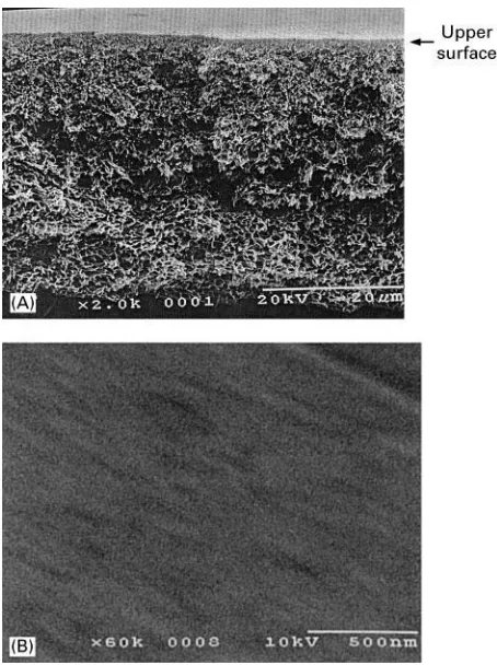
Figure 2 (A) SEM polysulfone porous support cross-section. (B) SEM polysulfone porous support (top view).
glass plate. After several minutes, immersion time in the water bath to remove all solvent, the newly for-med porous substrate is immersed again in a fresh water bath as aRnal rinse. This batchwise process can be scaled up and carried out as continuous processes employing pilot 1 foot (30 cm) wide or production 40-in wide (&100 cm) equipment. The advantages of utilizing the continuous process include not only the obvious efRciency but also better reproduci-bility in resultant porous support properties. However, it is sometimes necessary to pursue the laboratory batchwise process when experimenting with small quantities of costly new polymers or pro-cessing conditions that are not easily implemented on the larger-scale continuous equipment.
A typical polysulfone microporous support used in RO or NF IFC membrane fabrication is, by its pore size designation, an ultraRlter (UF) with surface pore sizes ranging from 0.005 to 0.05m. Since this size is an order of magnitude smaller than the interfacial Rlm thickness, it easily supports theRlm even under operating pressures as high as 1000 psi (6.9 MPa). The thickness of the PS support must be sufRcient to cover completely the carrier fabric surface plus irregularities caused by improper calendaring, debris and lack ofSatness during the casting operation. In practice the net thickness of the PS layer ranges from 25 to 75m and that of the carrier fabric upon which it lies ranges between 75 and 150m. Scanning elec-tron micrographs (SEM) of a typical PS porous support cross-section and top view are shown in Figure 2A and B, respectively. The anisotropic struc-ture is plainly evident with the Rnest and most sup-portive pores residing in the upper surface of the support. The Rnished PS support is normally stored fully immersed in water or at least damp and pro-tected from dust, debris and biological growth. In some cases it is necessary to include a biocide in the storage water, particularly if it is to be stored a long time. A simpliRed drawing of a continuous casting machine designed to manufacture PS porous supports in which a carrier fabric is used is given inFigure 3. A few additional comments regarding the porous support should be noted. In addition to polysulfone, other similar aromatic polyethers may be used such as polyether sulfone. However, these and other variants are signiRantly more expensive and, except for certain specialized applications, are generally not warranted. The Rnal PS support should be rinsed free of the casting dope solvent otherwise this residual may fuse the porous structure when the IFC membrane is dried.
Aqueous Amine Reactant Application
The two basic formulations used in the RO IFC membrane industry contain the diamines piperazine
(Pip) or m-phenylenediamine (MPD). Because both the reactivity and solubility (partition coefR -cients) of these two monomers are different, it is necessary to utilize each at different absolute concentrations as well as different concentration ratios with the cross-linker. When using the Pip for-mulation it is usually necessary to include an acid acceptor such as sodium hydroxide (NaOH) to neu-tralize the hydrochloric acid by-product of the poly-amidization reaction. This is not necessary when using MPD since it is a much weaker base than Pip and used in a higher excess concentration so that, excess MPD serves as its own acid acceptor. It is generally preferred also to include a surfactant in the aqueous amine formula to acid in the wetting and thus even coverage of the PS support. An anionic or neutral surfactant type is preferred.
Figure 3 Continuous casting machine for porous support.
the PS support and after a brief time interval is drained off leaving an even, wet layer. Depend-ing on the particular formulation the excess amine may be further removed by rubber roller, squeegee, or air knife. It is important that some degree of wetness remains prior to the contact with the cross-linker solution, otherwise the amine cannot transfer ef-fectively via the water}solvent interface.
Cross-Linker Reactant Application
The choice of solvent for the acyl chloride reactant is dictated by the following requirements:
1. It must completely dissolve the acyl chloride (or other cross-linker) but not react with it.
2. It must be insoluble or virtually insoluble in water. 3. It must not dissolve or swell porous support. 4. It must have a sufRcient volatility such that
membrane-degrading temperatures are not re-quired for its evaporation.
In practice, the only solvents meeting all of the above requirements are aliphatic hydrocarbons and chloroSuorocarbons (CFCs). There may also be some examples of hydrogenated chloroSuorocarbons (HCFCs) that are acceptable and at the same time are more environmentally friendly than the CFCs. For manufacturing purposes, further restrictions may in-clude preferences for Sash point above 1003F and (37.83C) and low level toxicity. As mentioned pre-viously, the concentration of cross-linker required will be different for the two types of diamines. The concentration of acyl chloride needed for the Pip
formulation is approximatelyRve times that needed for the MPD formulation.
The method of cross-link solution application is generally limited to those which do not disrupt the biphasic nature of the interfacial reaction. If excessive disturbance to this step occurs, the growing polymer may be disrupted, leading to thin Rlm disconti-nuity and ultimately to high salt passage through the defect regions. Dipping, pouring on gently, kiss coating, etc., are effective methods. For the la-boratory-scale techniques, excess acyl chloride cross-link solution is gently poured onto the amine solu-tion-coated PS support contained in the frame and kept horizontal for a brief period. The cross-link solution is then drained off vertically, leaving behind the delicate IFC Rlm residing between thin aqueous and solvent layers. The Rnal step involves some form of evaporation of these two solvents as described below.
Drying the IFC Membrane
Since the freshly polymerized thin Rlm resides on a thin layer of water, this layer must be removed for theRlm to strongly adhere to the PS support surface. It is also desirable to remove the cross-link solvent so that the Rnished IFC membrane can be safely and conveniently handled in a dry state.
Table 4 IFC membrane optimization variables: simple ap-proach
Aqueous solution
1. Amine monomer concentration
2. Acid acceptor concentration
3. Amount of solution applied to porous substrate
Organic solvent
4. Cross-link monomer concentration
5. Cross-link solution contact time with amine solution
6. Organic solvent volatility
[image:9.568.50.276.81.211.2]7. Drying temperature
[image:9.568.292.519.515.689.2]Figure 4 SEM piperazine IFC membrane (top view).
Figure 5 SEMm-phenylenediamine IFC membrane (top view). forms of heating are possible forced air can be used
with less heat because of the efRcient mechanical effect it has on liquid evaporation. This can be an advantage for IFC membranes that are vulnerable to excessive dehydration. In general, it is found that lower boiling solvents combined with lower drying temperatures often result in membranes with higher Suxes and lower salt rejections than their higher boiling, higher drying temperature counterparts. Of course, longer time periods of drying can be em-ployed in a similar manner with lower drying temper-atures to achieve a similar effect, but the choice is ultimately dictated by mechanical and space require-ments of the manufacturing equipment. For laborat-ory scale preparation, it is convenient to use forced hot air devices such as hair-dryers and/or laboratory convection ovens to dry the IFC membrane after the cross-link solution is drained off the frame. Be-cause the thinRlm is not yet adhered to the PS support excessive air velocity is to be avoided.
The laboratory scale membrane preparation method described in previous sections is now recal-led, combining the various steps together: Six inch (&15-cm) square pieces of a polysulfone ultraRlter support are clamped between two TeSon威frames and coated on the upper surface with an aqueous solution of the amine monomer for several seconds; the excess solution is removed by any of the various methods previously mentioned. This freshly coated surface is immediately contacted with the cross-linker}solvent solution horizontally for a period of several seconds then drained vertically for several seconds andRnally dried by either forced air and/or convection oven for several minutes. The precise conditions for each of the above steps will depend on the particular type of IFC membrane product that is desired, i.e. NF or RO application, and high productivity or high solute re-tention, etc., according to the development} perfor-mance relationships discussed in the previous sec-tions. A listing of the major IFC membrane
prepara-tion variables is given in Table 4. SEM pictures of Pip- and MPD-based membranes are given in Figures 4 and 5, in which difference in surface roughness is seen.Figure 6gives a simpliRed diagram of the continuous IFC membrane manufacturing process.
Testing and Optimization
Test Criteria
Figure 6 Continuous coating machine for IFC membrane.
Table 5 Test feeds for IFC RO and NF membranes RO membranes
35 000 ppm NaCl 1500 ppm NaCl 1500 ppm NaCl 1500 ppm isopropanol
800 psig 150}225 psig 1000 ppm CaCl2 150}225 psig
150}225 psig NF membranes
500 ppm NaCl 500 ppm MgSO4 500 ppm NaCl 500 ppm sucrose
75 psig 75 psig 300 ppm MgSO4 75 psig
75 psig of solutes, or test pressures to suit the desired
applica-tion for the membrane.
The permeate quantity and quality are measured for each membrane sample tested and utilized as performance criteria. In the desalination industry, the former is termed membraneSux, with units of gal-lons/foot2-day (gfd) (;40.8 L/m-day) and the latter as salt rejection (%). Flux measurements are made by collecting a volume of permeate under a controlled temperature and time interval. Knowing the active area of the membrane sample and utilizing a temper-ature correction factor for the viscosity of water, one can calculate theSux normalized to 253C. Salt rejec-tion is calculated from electroconductivity measure-ments of the permeates with correction for speciRc conductance as a function of sodium chloride
concen-tration, or via speciRc ion probe measurement. Salt rejection isRnally calculated as
1!permeate p.p.m. feed p.p.m. ;100In the case of organic solutes, measurements of per-meate and feed are done with a total organic carbon (TOC) analyser with rejection calculated in the same manner as before.
[image:10.568.53.516.614.711.2]99.3% membrane, that is, one with a lowerSux but higher rejection. A simple ranking method, if the salt rejection of the membrane is 75% or higher, is to take the ratio of Sux/salt passage (F/SP) in which salt passage is simply 100! salt rejection. This value correlates well with the more sophisticated ranking calculation of A2/B, in which A is the pure water permeability constant (g mol cm\2s\1atm\1) and B is the salt transport coefRcient (cm s\1). In the discussion below, both a simple and a more sophisti-cated performance optimization example are present-ed for membrane development.
Simple Approach Optimization
If one has some development experience with a par-ticular amine and cross-linker reactant system such that the workable range of reactant concentrations and processing conditions are at least roughly deR n-able, or if highly optimized membrane performance is not essential, a simpliRed approach may be pursued. A listing of the recommended minimum number of optimization variables has been given in Table 4. The membrane optimization plan should be carried out in the order shown in this table since it is ordered from highest to the lowest criticality. This approach relies on selecting previously known conditions or educated estimates of some of the variables to be surveyed. The amine monomer concentration experiment would be-gin by comparing amine concentrations ranbe-ging, for example, from x to 3x with increments in-between while holding all other variables in Table 4 constant. This requires some discretion in selecting median values of the held constant variables based on prior knowledge. After determining the ‘optimum’ amine concentration one would proceed in order to the next variable and carry out the next experiment, holding all other variables constant except the acid acceptor concentration that is to be varied. This procedure continues until all the variables have been individ-ually optimized. It is strongly recommended after a once-through optimization to reiterate this process at least once more since new values of many of the variables are likely to have been established. The second time through is likely to result in reRnements of both the optimization variable values and the membrane performance.
It should be pointed out that this simple single-variable optimization approach can suffer errors due to interactive variables that can only be optimized in concert. For example, it is likely that, consistent with general principles of chemical reactants, when the amine concentration increases the need for cross-linker increases but so does that for the acid acceptor. In this example there is a three-variable interaction, not mere-ly the two-variable one that the simple method
exam-ines. Thus it is often desirable to consider a more sophisticated approach to optimization in which the best combination of variables is found. A multivari-able optimization process is offered below.
Self-Directing Optimization Approach (SDO)
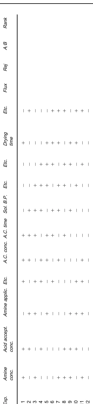
In the SDO process, a regular simplex inKvariables is constructed. The experiment can be intiated inK vari-ables withK#1 experiments and upon completion of theK#1 experiments, the results are ranked from best to worst. In the case of IFC desalination mem-branes, ranking is performed using either F/SP or A2/B calculations made from the Sux and rejection results from a speciRed test feed type and operating pressure. An example of a Placket}Burmann SDO plan containing 11 variablesA}Kin 12 experiments is presented inTable 6. Corresponding to the#and !symbols are high and low levels, respectively, to be selected for each variable A}K. The experiments 1}12 are carried out as one series in a random order. After completion of theRrst series of 12 experi-ments, the best eight cases, for example, will have the averages of each of the variables calculated. These average values are then multiplied by 2, then from these are subtracted each of the conditions of the four worst cases. The four new experiments cre-ated are then run and ranked against the previous eight best cases as before with subsequent elimination of the four worst cases. This process is repeated several times, each time eliminating the worst cases and creating new ones to be compared with the pre-vious best. Eventually the variables will be found to converge such that the optimization is complete.
Future Developments
Ta bl e 6 Placke tt } B u rm an op ti m iz a ti o n p la n Exp . A m in e co n c . Aci d acce p t. co n c . Am in e a pp lic . E tc . A .C . c on c . A. C . ti me So l. B .P. Et c . Et c . D ry in g ti m e Et c . F lux R e j A / BR a n k 1 # # ! # ##!! ! # ! 2 ! # # ! ###! ! ! # 3 # ! # # !### ! ! ! 4 ! # ! # #!## # ! ! 5 ! ! # ! ##!# # # ! 6 ! ! ! # !##! # # # 7 # ! ! ! #!## ! # # 8 # # ! ! !#!# # ! # 9 # # # ! !!#! # # ! 10 ! # # # !!!# ! # # 11 # ! # # #!!! # ! # 12 ! ! ! ! !!!! ! ! !
There are performance gaps in presently available membrane products for the NF area of separations involving species with relative molecular masses ranging from 100 to 3000. It is forseeble that markets will expand for NF membrane applications in high value separations for biotech, chemical, food, and pharmaceutical industries if well-deRned relative molecular mass cutoffs can be achieved.
With respect to commercial IFC membrane manu-facture, there is a need for improved uniformity and quality of carrier fabrics upon which the porous sup-port is cast. Lack of control here can result in defects that are translated right through the completed com-posite membrane product. An additional future goal is the development of real-time membraneRlm integ-rity and/or performance measurement so that correc-tions to the process can be made during the course of the manufacture.
See also: II/Membrane Separations: Membrane Prep-aration; Reverse Osmosis; Ultrafiltration.
Further Reading
Al-Gholaikah A, El Ramly N, Janyoon I and Seaton R
(1978) The world’sRrst large seawater reverse osmosis
desalination plant, at Jeddah, Kingdom of Saudi Arabia.
Desalination27: 215}231.
Cadotte JE (1984) In: Lloyd DR (ed.)Evolution of
Com-posite Reverse Osmosis Membranes,Materials Science of Synthetic Membranes, p. 273. Washington, DC: ACS Symposium Series.
Cadotte JE, Cobian KE, Forester RH and Petersen RJ
(1976)Continued Evaluation of Insitu-Formed
Conden-sation Polymers for Reverse Osmosis Membranes. NTIS
Report No. PB 253193. SpringReld: US Department of
Interior.
Cadotte JE, Petersen RJ, Larson RE and Erickson EE (1980)
A new thinRlm composite membrane for seawater
de-salting applications. Desalination 32: 25}31.
Amster-dam: Elsevier Science B.V.
Enkelmann V and Wegner G (1976) Mechanism of inter-facial polycondensation and the direct synthesis of stable
polyamide membranes.Makromolekulare Chemie177:
3177}3189.
Enkelmann V and Wegner G (1972) Makromolekulare
Chemie157: 303.
Hirose M, Minamizaki Y and Kamiyama Y (1997) The relationship between polymer molecular structure of RO membrane skin layers and their RO performances.
Journal of Membrane Science123: 153}163.
Morgan PW, Kwolek S L and Wittbecker EL (1959)
Inter-facial polycondensation I and II. Journal of Polymer
ScienceXL: 289}326.
Riley RL, Fox RL, Lyons CEet al. (1976) Spiral-wound
poly(ether amide) thin-Rlm composite membrane
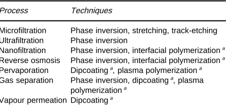
[image:12.568.91.248.34.713.2]Table 1 Frequently used techniques for the preparation of syn-thetic polymeric membranes
Process Techniques
Microfiltration Phase inversion, stretching, track-etching Ultrafiltration Phase inversion
Nanofiltration Phase inversion, interfacial polymerizationa
Reverse osmosis Phase inversion, interfacial polymerizationa
Pervaporation Dipcoatinga, plasma polymerizationa
Gas separation Phase inversion, dipcoatinga, plasma
polymerizationa
Vapour permeation Dipcoatinga
aSupport layer prepared by phase inversion.
Rozelle LT, Cadotte JE, Corneliussen RD and Erickson EE
(1967) Development of New Reverse Osmosis
Mem-branes for Desalination, Report No. PB-206329.
Spring-Reld, IL: VA National Technical Information Service.
Rozelle LT, Cadotte JE, Cobian KE and Kopp CV Jr (1977)
In: Souriragan S (ed.)Nonpolysacharide Membranes for
Reverse Osmosis. NS-100 Membranes for Reverse Osmosis and Synthetic Membranes, p. 249. Ottawa, Canada: National Research Council Canada.
Souriragan S (1970) Reverse Osmosis. New York:
Aca-demic Press.
Phase Inversion Membranes
M. Mulder, University of Twente, Enschede, The Netherlands
Copyright^ 2000 Academic Press
Introduction
Phase inversion is the most versatile technique with which to prepare polymeric membranes. A variety of morphologies can be obtained that are suitable for different applications, from microRltration membranes with very porous structures, to more dense reverse osmosis membranes, to gas separation and pervaporation membranes, with a complete de-fect-free structure. Table 1gives an overview of the techniques that are commonly applied for the prep-aration of synthetic polymeric membranes.
Most commercially available membranes are pre-pared by phase inversion. This is a process by which a polymer is transformed from a liquid or soluble state to a solid state. The concept of phase inversion covers a range of different techniques such as immersion precipitation or ‘diffusion-induced phase separation’, thermal-induced phase separation, ‘vapour-phase’ precipitation and precipitation by controlled evaporation. The technique of phase inver-sion has been known for quite some time; the Rrst paper on the preparation of porous nitrocellulose membranes by phase inversion appeared in 1907.
After World War I the number of publications on membrane preparation and characterization in-creased signiRcantly and led to the development of theRrst methods for producing porous nitrocellulose membranes in a reproducible way. The ‘MembranR l-tergesellschaft Sartorius-Werke’ in GoKttingen was the Rrst company to produce microRltration membranes on a commercial scale, based on the work of Zsig-mondy. This early work on preparation and charac-terization was reviewed by Ferry in 1936.