Semiconductor and Integrated Optoelectronics (SIOE) Conference 2005
Optimisation of a two colour pumped Tm
3
1
-doped
ZBLAN fibre amplifier at 1.49
m
m
S. Tessarin, M. Lynch, J.F. Donegan and G. Maze´
Abstract:The authors have constructed a 4 metre length thulium-doped ZBLAN fibre amplifier optically pumped at 0.8mm by a tuneable Ti : Sapphire and at 1.06mm by an Nd3þ: YAG laser. The authors obtained 12.5 dB for small-signal gain at 60 mW for the two pumps’ optical power. The behaviour of the amplifier has been analysed with the optical power of the signal approaching the saturation condition (25 dBm) and at different wavelengths for the Ti : Sapphire pump laser. A model was developed for the optimisation of the amplifier for signal power below the saturation intensity at wavelengths between 1.49 and 1.53mm (S-band). This shows an empirical quadratic dependence of the Nd3þ: YAG power with respect to the Ti : Sapphire power in order to obtain the maximum photon conversion efficiency making the optimised amplifier employable as a booster amplifier in the supporting telecommunication band.
1 Introduction
Much research into fibre amplifiers is focused on expanding the low-loss region of telecommunication transmission band wavelengths that are not yet covered by erbium and gain-shifted erbium fibre amplifiers. Thulium (Tm3þ) as dopant in glass has a fluorescence transition centred at 1.47mm, which can be used as an amplifier at wavelengths between 1.43 and 1.53mm (Sþ-band extends from 1.43 to 1.49mm and S-band extends from 1.49 to 1.53mm)[1, 2]. In contrast to erbium amplifiers, thulium needs a low-phonon-energy host glass such as ZBLAN (ZnF4– BF2–
LaF2– AlF2– NaF2, a heavy metal fluoride glass) in which
the 1.47mm transition of the Tm3þions has higher radiative efficiency and the metastable level has a longer lifetime compared with silica.
However, as depicted in the energy level diagram (Fig. 1), the upper level for the transition3H
4has a lifetime
of 1 ms, whereas the lower level3F4has a lifetime of the
order of 10 ms. This type of situation has been referred to as self-terminating transition and creates a ‘bottleneck’, where the population builds up in the terminating level, reducing the overall efficiency of the amplifier.
Higher efficiency can be achieved by upconverting the excess 3F4 ion population to the 3F2–3F3 thermally
coupled levels through an excited state absorption (ESA) transition, which has an energy corresponding to wave-lengths from 1.040 to 1.070mm. A residual ground state absorption is also present at these wavelengths so single-wavelength pumping with Nd3þ: YAG (1.064mm) or Yb3þfibre lasers (1.047mm) will generally produce some low-level of amplification [3]. However, because of the
low pump absorption, long fluoride fibre lengths are necess-ary in order to obtain large gain.
The efficiency can be improved by directly pumping one of the ground state absorption transitions while the 1mm radiation will be used essentially for upconverting the3F4
electrons population [4]. This type of configuration has been used to obtain the highest conversion efficiency observed to date for Tm3þ-doped fibre amplifiers with pumping at 1.56mm (ground state) and 1.40mm (excited state)[5].
The 800 nm technology for high power semiconductor lasers is well established because of the market for pump lasers for erbium fibre amplifiers [6] and for this reason, we have focused on this wavelength for pumping the strong thulium ground state absorption centred at 790 nm. In contrast, technology for high-power laser diodes at 1.05mm is not fully developed and high powers are not readily obtainable.
There is clearly a need to investigate the performance of these dual pumped systems, particularly with regard to balancing the powers of the pump lasers for optimum amplifier performance. The aim of this paper is to present the experimental results that have been obtained for a thulium amplifier pumped at 1.06mm and around 0.79mm and use the measurements as a starting point for the construction of a model of the amplifier. This will allow us to optimise the ratio of the two pump powers involved.
2 Experimental set-up
A 4 metre length ZBLAN fluoride glass fibre with 2000 p.p.m. thulium doping level, 4.4-mm core diameter and NA¼0.17 was pumped simultaneously by a Ti : Sapphire tuneable laser in the range 760 – 820 nm and a YAG laser (1.064mm). The pump lasers are combined using a Corning SMF-28 fibre chromatic coupler.
A single mode diode laser at 1.49mm was used as a signal source to measure the amplifier gain. This is coupled counter-propagating to the pump lasers and detected with an optical spectrum analyser (OSA) as depicted inFig. 2a.
The small-signal gain tuning curve along the amplifying wavelength region was measured by modifying the set-up
#IEE, 2006
IEE Proceedingsonline no. 20050053
doi:10.1049/ip-opt:20050053
Paper first received 2nd June and in revised form 1st October 2005
S. Tessarin, M. Lynch and J.F. Donegan are with Semiconductor Photonics Group, School of Physics, Trinity College Dublin 2, Ireland
presented inFig. 2busing a broadband light source, a 75 W Xenon lamp coupled into a single mode fibre. This amplified signal from the fibre output was measured by using the OSA as a monochromator and passing its (electrical) signal output to a lock-in amplifier. Spectral resolution was set to 0.2 nm. The gain between 1.45 and 1.55mm was recorded for different values of the 790 nm pump optical power.
3 Experimental results
With the optical power of both pumps at 60 mW and the Ti : Sapphire tuned to 790 nm, we have recorded from the OSA an amplification of 12.5 dB gain in the small-signal regime. In this case, the signal power was around
240 dBm and does not have an impact on the ion popu-lation of the levels involved in the amplification process.
The amplified Tm3þ fluorescence and the small-signal gain are shown in Fig. 3. The gain due to the 1.064-mm Nd3þ: YAG pump alone was 2 dB, whereas adding the 790 nm pump increased the gain to 12.5 dB. We also measured the behaviour of the amplifier at higher signal powers and at 25 dBm input signal power, the gain decreases to 0.7 dB below the small-signal case. For the model discussed in the next section, we chose an operating point of210 dBm input signal level as representative of the onset of gain saturation.
The spectral response of the gain, measured with a broad-band source, is shown in Fig. 4. The gain profile shows a significant redshift from the emission band which is centred at 1.47mm and this is attributed to re-absorption.
Since changing the Ti : Sapphire wavelength will change the absorption cross-section, the pump at 790 nm can be tailored to access the value for the absorption cross-section where the maximum photon conversion efficiency (PCE) is obtained. This is defined as the ratio of the photon converted into signal and the number of injected pump photons
PCE¼ P
s outP
s in
ls PTiSp l
p TiSþP
p YAGl
p YAG
ð1Þ
wherePsis the signal input and output powers in the ampli-fier, ls the signal wavelength and PTiSp , lTiSp , PYAGp and lYAGp are the powers and wavelengths for the Ti : Sapphire
and the Nd3þ: YAG pump lasers. As we have observed in
Fig. 5 for 4 m length, the maximum PCE and gain
achievable for 60 mW pump power of both Ti : Sapphire and Nd3þ: YAG is with the Ti : Sapphire tuned to 800 nm.
4 Optimisation
Optimisation criteria for fibre amplifiers will strongly depend on the intended application, for example pre-amplifiers require high gain with good gain linearity, whereas for high signal power (booster amplifier), output power and pumping efficiency are important considerations. Fig. 1 Diagram of the energy levels
Upward arrows represent photons absorbed from the 1.064mm
pump, the ground state absorption at 790 nm and signal excited state absorption, whereas the downward arrow represents the signal
stimulated emission at 1.49mm. Each transition has an associated
cross-section (4). The population densities for the levels involved in
the model are namedniwithi¼1 to 5. Lifetimes of the amplifying
levels are also given
Fig. 3 Detected Tm3þfluorescence at 1.47mm is reported when
optical power for the two pumps is set to 60 mW and when only the 60 mW of 1.064mm is present
Inset shows the effect on the signal probe at 1.49mm
Fig. 2 Schematic diagram showing the outline of the Tm amplifier
The two pumps are coupled together by chromatic fibre coupler (CFC)
a The signal from a 1.49-mm single-mode laser diode is detected
from the output of the amplifier after a polarising beam splitter (PBS). The polarisation controller (PC) maximises the signal through-put in the optical spectrum analyser (OSA)
b Light from a Xenon lamp is detected by reading the output of the
OSA in a lock-in amplifier (LIA)
Fig. 4 Gain for a different wavelength within the amplification band
(1) Ti : Sapphire power of 30 mW, Nd3þ
: YAG power 60 mW;
[image:2.595.309.545.30.202.2] [image:2.595.64.268.32.165.2] [image:2.595.349.507.611.731.2]Here, we concentrate on the intermediate case with
210 dBm input signal level as representative of the onset of gain saturation. The optimisation criterion we have chosen is to maximise the pump to signal conversion effi-ciency. This is important for a booster amplifier as the per-formance of a practical amplifier is often limited by the pump powers available from laser diodes. At these signal levels, the effect of the amplified spontaneous emission is not significant and is not considered here.
For the dual-wavelength pumped Tm3þ system, the terminating level is depleted by the secondary pump so we can expect it to have good saturation characteristics once the photon conversion efficiency is high. An estimate of the saturation intensity in the limit of total bleaching of the terminating level is given by[7]
ISats ¼ hys
ss set40
ð2Þ
so for a cross-section of the order of 2.510225m2and a lifetime of the3H4level (number 4, inFig. 1) of 1 ms gives
a saturation intensity of 51011mW/m2or, in the case of our fibre, gives a saturating signal power ofþ9 dBm.
This makes the Tm3þtwo-colour pumped fibre particu-larly suitable for a gain-shifted booster amplifier since it can operate at a high-level of signal input and low pump powers at wavelengths between 1.49 and 1.53mm (S-band). As experimentally observed, we selected the starting point for our analysis at the input signal power of
210 dBm, the Ti : Sapphire tuned at 800 nm and the fibre with the same doping and parameters (NA, core diameter, length) as the one tested.
Since operation at 1.47mm is reduced by lower relative inversion and/or re-absorption, we limit our analysis to the 1.49-mm operation where these effects can be neglected. The model that has been developed is similar to that published by Kasamatsu et al. [8] where the steady-state population of the relevant levels has been numerically integrated simultaneously with the propagation equations using a fourth-order Runge-Kutta method.
Thulium in ZBLAN at 1.47mm is a four-level system and therefore high conversion efficiency is expected. A threshold power is due to the self-terminating nature of the 1.49mm transition; however, in the presence of an effi-cient upconversion for the3H4population, the gain
coeffi-cient at 1.49mmgs¼s se s
n4–sesas n2is positive due to the
small sesas [9] and the optimum fibre length is set in
order to absorb as much pump power as possible [10]. The sses is the signal stimulated emission cross-section
whereas sesas is the signal ESA cross-section and n4 and
n2are the population densities of the two levels involved
in the process of signal amplification as depicted inFig. 1. The signal propagation is governed by a differential equation wherePsis the signal power at the zpoint in the fibre
dPs dz ¼ g
sPs ð3Þ
the minus sign is due to the counter propagation of pumps and signals and thegsis the gain coefficient.
Equation (3) has to be integrated simultaneously with the pump propagation equations and can be written as
dPTiS
dz ¼ Gðl
TiSÞgTiSPTiSa
800
dPYAG
dz ¼ Gðl YAGÞ
gYAGPYAGa1064
ð4Þ
whereG(lTiS) andG(lYAG) are coefficients which take into account the multimode nature of the two pumps anda800
anda1064 are backscattering losses of the ZBLAN fibre at
the two pumps wavelength. We used the approximation
a800’a1064’0.1 dB/m as reported in the specification
of the ZBLAN fibre.
The gTiS and gYAG terms in (4) are the absorption coefficients for the two pumps given by
gTiS¼ sagsaðlTiSÞn1 ð5Þ
gYAG¼ sð1Þ
a ðl YAG
Þn1sað2Þðl YAG
Þn2sað3Þðl YAG
Þn4
where the various absorption cross-sections involved and the population densities of the electronic levels (ni) are
shown inFig. 1and listed inTable 1.
All the population densities are described by rate equations and the steady-state value is obtained by algebraically solving the rate equations together with the conservation equation.
The structure of the amplifier was taken into account by the two boundary conditions to which (4) and (5) are sub-jected and represent the fact that the two pumps are insub-jected in the fibre atz¼0 while the signal is counter-propagating from the other end of the active fibre.
The Tm3þ-doped ZBLAN fibre has been designed in order to obtain high transmission with Corning SMF-28 fibre with Marcuse’s polynomial spot size [11] of the active fibre matching with the fundamental LP01 mode of the
trans-mission fibre above the cut-off wavelength. The Kasamatsu overlapping factorG(l) in (4) describes the overlap of the pump mode with the fibre core dopant. This has been obtained by measuring the transmission of the fibre at the Ti : Sapphire wavelength. This gives G(lTiS)¼0.52. The G(lYAG) was
estimated to be equal to 0.94 from the ratio of the radius of the fibre and the Gaussian spot size calculated from the poly-nomial expression reported in[12].
All the parameters used in the simulation are reported in Table 1.
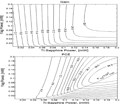
Fig. 6shows the calculated gain and the PCE as a func-tion of the two pump powers. The gain measured for 30 mW of Ti : Sapphire and 60 mW of Nd3þ: YAG as shown in Fig. 4 is 7.2 dB and the calculated value is 7.04 dB, whereas with 60 mW of Ti : Sapphire the measured gain is 12.5 dB and the calculated gain is 13.2 dB, showing good agreement. For a given Ti : Sapphire power, a fast increase in gain with Nd3þ: YAG power is seen, because of the depletion of the terminating level, after which the gain is almost independent of the Nd3þ: YAG power due to the small GSA absorption at 1.064mm. The transition Fig. 5 Measured gain and PCE observed for different
[image:3.595.70.260.30.168.2]between these two regimes can be seen as a maximum in the PCE. At a given Ti : Sapphire power, the PCE will sharply rise with the increase of the Nd3þ: YAG power and then as the terminating level is bleached, the PCE will decrease. The contour of maximum PCE gives the optimum pump power combination and can be approximated by a quadratic equation given the best ratio between Ti : Sapphire power and Nd3þ: YAG power as
PYAG¼3:2P2Ti:Sapphire ð6Þ We have defined the PCE as the number of stimulated emitted photons normalised by the total number of pump photons (eq. 6.2); considering only the two strongest absorption mechanisms the theoretical limit will be 50%. However, a more reasonable figure observed in a real ampli-fier[13]is around 30% which is close to the limit reached by PCE for Ti : Sapphire power above 150 mW and Nd3þ: YAG power above 75 mW. Longer fibre length is not needed since high PCE performance can be achieved in the short fibre. The longer fibre will reduce the obtainable limit because of the scattering loss associated with the two pumps and the signal.
In Fig. 7, we report the expected gain within the fibre length for the two pump powers. Starting from the left-hand side of Fig. 7, it is possible to calculate the 800 nm power required in order to obtain the maximum PCE and the gain obtained as a function of the length of the active fibre. The method can be used for different pumping schemes and can be tailored in order to fulfil different types of conditions and fibre geometry.
5 Conclusions
We have constructed a 4 m length thulium-doped ZBLAN fibre amplifier pumped by a Nd3þ: YAG (1.064mm) laser and a Ti : Sapphire (800 nm) laser with the intention of opti-mising the operation of the amplifier for high-signal gain at a wavelength above 1.49mm. Experimental observations suggest the best pump wavelength is located at 800 nm for the Ti : Sapphire and practical signal operation of210 dBm does not considerably affect the gain at 1.49mm.
High-signal operation requires maximum photon conversion efficiency and we have developed a model, not limited to the small-signal gain, in order to find the operation points where the maximum PCE is obtained for the lowest optical power of the two pumps involved.
For a given value of the Ti : Sapphire power, we estab-lished that the corresponding value for the Nd3þ: YAG power obeys a quadratic relationship.
We profiled the gain within the fibre length of the ampli-fier so that the required length in order to achieve the desired gain can be found.
Fig. 7 Gain predicted within the fibre for the two pumps when the power for the Nd3þ:YAG is correlated to the Ti:Sapphire by
the relationship (6)
Fig. 6 Calculated gain and PCE for different values of the two pump powers
[image:4.595.285.529.43.376.2]Maximum value for the PCE with respect to the pumps is shown as a dashed line
Table 1: Parameters that have been used in the numerical simulation
Parameter Unit Symbol Value Remarks
Thulium concentration m23 3.2
1025 Specification
Core diameter mm 4.4 Specification
NA 0.17 Specification
Background loss dB/m 0.1 Specification
Signal stimulated emission cross-section m2 s
ses 1.510225 [14]
Signal ESA cross-section m2 sesas 0.910227 [14]
Absorption cross-section 800 nm m2 s
agsa 1.910225 [14]
Absorption cross-section 1.064mm m2 s
a
(1) 1.1
10227 [15]
m2 sa
(2)
8.210225 [15]
m2 s
a
(3) 2.5
10227 [15]
Overlapping factor 800 nm G(lTiS) 0.52 Measured
Overlapping factor 1.064mm G(lYAG) 0.94 Estimated[12]
[image:4.595.47.513.45.236.2] [image:4.595.50.287.521.726.2]6 Acknowledgment
The Tm3þ ZBLAN doped fibre used in this work was provided by Le Verre Fluore’, Brittany.
7 References
1 Roy, F.: ‘Recent advances in thulium-doped fiber amplifiers’. Optical Fiber Communication Conference and Exhibit, OFC ’02, 2002 2 Caspary, R., Unrau, U.B., and Kowalsky, W.: ‘Recent progress
on S-band fiber amplifiers’. Proc. 5th Int. Conf. on Transparent Optical Networks, 2003
3 Bourliaguet, B., Emond, F., Mohrdiek, S., Jacob-Poulin, A.-C., Cortes, P.-Y., and Lauzon, J.: ‘Thulium-doped fibre amplifier using 1055 nm laser diode pumping configuration’,Electron. Lett., 2002,
38, pp. 447 – 448
4 Roy, F., Bayart, D., Le Sauze, A., and Baniel, P.: ‘Noise and gain band management of thulium-doped fiber amplifier with dual-wavelength pumping schemes’, IEEE Photonics Technol. Lett., 2001, 13, pp. 788 – 790
5 Aozasa, S., Masuda, H., Ono, H., Sakamoto, T., Kanamori, T., Ohishi, Y., and Shimizu, M.: ‘1480 – 1510 nm band Tm-doped fibre amplifier with high-power conversion efficiency of 42%’, Electron. Lett., 2001,37, pp. 1157 – 1158
6 Pedersen, B., Miniscalco, W.J., and Zemon, S.A.: ‘Evaluation of the 800 nm pump band for erbium-doped fiber amplifiers’, Lightwave Technol. J., 1992,10, pp. 1041 – 1049
7 Komukai, T., Yamamoto, T., Sugawa, T., and Miyajima, Y.: ‘Upconversion pumped thulium-doped fluoride fiber amplifier and
laser operating at 1.47mm’,IEEE J. Quantum Electron., 1995,31, pp. 1880 – 1889
8 Kasamatsu, T., Yano, Y., and Ono, T.: ‘1.49-mm-band gain-shifted thulium-doped fiber amplifier for WDM transmission systems’, J. Lightwave Technol., 2002,20, pp. 1826 – 1838
9 de Sousa, D.F., Peters, V., Huber, G., Toncelli, A., Parisi, D., and Tonelli, M.: ‘Pump modulation frequency resolved excited state absorption spectra in Tm3þ-doped YLF’, Appl. Phys. B: Lasers Optics, 2003,77, pp. 817 – 822
10 Ruhl, F.F.: ‘Figures of merit for doped fibre amplifiers in 1300 nm and 1550 nm windows’,Electron. Lett., 1991,27, pp. 1605 – 1607 11 Marcuse, D., and Stone, J.: ‘Coupling efficiency of front surface and
multilayer mirrors as fiber-end reflectors’, J. Lightwave Technol., 1986,4, pp. 377 – 381
12 Whitley, T.J., and Wyatt, R.: ‘Alternative Gaussian spot size polynomial for use with doped fiber amplifiers’, IEEE Photonics Technol. Lett., 1993,5, pp. 1325 – 1327
13 Kasamatsu, T., Yano, Y., and Ono, T.: ‘Gain-shifted dual-wavelength-pumped thulium-doped fiber amplifier for WDM signals in the 1.48 – 1.51-mm wavelength region’, IEEE Photonics Technol. Lett., 2001,13, pp. 31 – 33
14 Sakamoto, T.: ‘Spectroscopy of thulium-doped halide glass’ in Hewak, D.W. (Ed.): ‘Properties, processing and applications of glass and rare earth-doped glasses for optical fibres’. EMIS Datareviews Series, no. 22 (Inspec, IEE, Stevenage, UK, 1998);IEE Proc., Optoelectron., 2004,151, p. 236