February, 1964
\1
J
/
CDrn~uter&
,
:
and automation
4 REASONS FOR BUYING ONLY PREMIUM TAPE
(Memo~eJC,
off
COlLn~se~)
Reduced maintenance down-time. Premium tape increases head life and reduces head replace-ment. Its better adhesion of oxide coating and tougher, smoother coating surface minimize operat-ing interruptions resultoperat-ing from oxide build-up on heads and guides.
Memorex magnetic tape is premium tape.
Greater reliability. Premium tape remains error ' free - pass after pass, reel after reel- and pro-vides greater security of data in demanding routines. Despite the somewhat higher price of premium tape, few users can afford to miss the economy inherent in its greater reliability.
Memorex magnetic tape is premium tape.
Memorex tape is premium tape. No need to pre-check it. You can place Memorex computer tape directly in service-reel after service-reel.
Memorcx certification means what it says: Memorex com-puter tape
l§.
error-free. Extra care, extra steps and scrupu-lous attention to every detail make it that way. We know the importance to you of having a tape you can depend on.Longer life. Premium tape minImIzes tape strip-ping. It assures error-free performance long after inferior tape breaks doWn and becomes loaded with dropouts. The more severe the use, the more the economies afforded by premium tape's tougher, smoother coating.
Memorex ma,:!netic tape is premium tape.
No rejects. Premium tape provides freedom from rejects because it is always read-,pass perfect- reel after reel. Its price is higher, perhaps. But its effec-tive cost is less because premium tape delivers machine-time savings by eliminating pre-testing and maximizing error-free operation.
Memorex magnetic tape is premium tape.
Are you on our mailing list to receive the Memorex Monograph Series of informative technical literature? Write 1176 Shulman Road, Santa Clara, California
MEMOREX
PRECISION MAGNETIC TAPECircle No. 5 on Readers Service Card
In other disk files, the read/write head moves to the informa-tion track on a phonograph-like armature. This takes from 90 to 600 milliseconds. The new Burroughs random access disk file has an average access speed of 20 milliseconds-nearly
five times faster than the fastest conventional disk file. Reason?
Each track has its own read/write head, fixed less than a hair above it. This new concept eliminates head movement.
This new system is also easy to use-in planning, program-ing and actual operation. Such techniques as rapid dumpprogram-ing and loading, sorting, use of the file as an extension of memory, and report generation minimize the need for time and per-sonnel. And that means cutting your data processing costs.
All-electronic controls insure reliability. Example: Every seg-ment written on the disk file has a multiple character check code recorded along with it. During read-back, the check code is regenerated and compared to the recorded check code assuring complete accuracy during reading and writing.
This new third-generation disk file is built to complement our B 5000 and B 200 series computers. You'll find it highly responsive to your individual needs, present and future, as you move toward on-line data processing. We'd like to tell you more. Write us at Detroit, Michigan 48232. Burroughs-TM
Burroughs Co..rporation
Circle No. 15 on Readers Service Card
FOR PENNIES, YOUR COMPUTER CAN PLOT DATA DIRECTLY
IN EASY·YO·READ GRAPHIC FORM
Why try to visualize the significance of masses of digital data -or plot it laboriously by hand? The new EAI DATAPLOTTERe Series 3110/3120/3130 automatically plots digital information on-line from almost any digital computer or from punched cards or punched tape. It will plot lines", points or symbols with extreme accuracy at speeds up to 120 points per minute on charts up to 10· x 15". YOU CAN RENT IT FOR $3.50 AN HOUR.
If you want to get more out of your computer-generated data, write for information on the new EAI DATAPLOTTER today.
EAl
e- - - -ELECTRONIC ASSOCIATES, INC.,
Long Branch} New JerseyADVANCED SYSTEMS ANALYSIS AND COMPUTATION SERVICES/ANALOG COMPUTERS/HYBRID ANALOG·DIGITAL COMPUTATION EQUIPMENT/SIMULATION SYSTEMS/ SCIENTIFIC AND LABORATORY INSTRUMENTS/INDUSTRIAL PROCESS CONTROL SYSTEMS/PHOTOGRAMMETRIC EQUIPMENT/RANGE INSTRUMENTATION SYSTEMS/TEST AND CHECK·OUT SYSTEMS/MILITARY AND INDUSTRIAL RESEARCH AND DEVELOPMENT SERVICES/FIELD ENGINEERING AND EQUIPMENT MAINTENANCE SERVICES.
P D P - 5
A HIGH SPEED
CORE MEMORY
GENERAL PURPOSE
COMPUTER FOR
$27,000
SCIENTIFIC COMPUTATIONS · SYSTEM AND PROCESS
CONTROL · DATA COLLECTION AND REDUCTION
Based on
DIGITACShigh
re-liability line of logic modules,
the PDP-5 offers this unique
combination of machine
fea-tures:
• 6-microsecond cycle
time -
12-bit word
length
• 55,555
additions-per-second computation
rate
• 1024-
or 4096-word,
random access,
mag-netic core memory
• 24-bit arithmetic
• 2-megacycle bit input
via built-in data
chan-nel
• Program interrupt for
input-output devices
• I/O Buss for direct
con-nection of 64 externa I
devices
• Co m p I ete softwa re
package -
including
FORTRAN, assembler,
double-precision,
float-ing point, and
mainte-nance routines
Centra I processor with
1024-word memory,
keyboard-COMPUTERS and AUTOMATION for February, 1964
printer, paper tape reader
and punch -
$24,000. With
4096-word
memory-$27.,000.
EQUIPMENT
CORPORATION
MAYNARD,MASSACHUSETTSSALES OFFICES: Los Angeles &
Palo Alto • Washington, D. C. • Parsippany, N. J .• Monroeville, Pa. • Park Ridge, III. • ottawa, Canada • Munich, Germany • Sydney, Australia .
LEAK DETECTION
~
MARKING FINAL MEASUREMENT(BRIDGE II)
USING A COMPUTER
FOR QUALITY CONTROL
--OF AUTOMATIC PRODUCTION
FIGURE 1. AUTOMATED PRODUCTION LINE F
]. H. Boatwright
Western Electric Co.
New
York~N. Y.
[image:6.634.43.593.94.642.2]COATING FURNACE II FOR
_, _ PNEUMATIC TUBE
---2~SCORE MEASUREMENT
'''''--'''-,.".T">--OR DEPOSITED CARBON RESIST'''''--'''-,.".T">--ORS
At the North Carolina works of the Western Electric: Company an electronic digital computer has been used in a completely closed loop to control an automatic produc-tion line by the use of statistical quality control methods.
Reliability
A significant outgrowth of Western Electric's activity in the development of complex anti-missile defense systems has been the need [or much more reliable electrical building blocks. Components having a degree of reliability which gave quite acceptable performance in the simplest military electronics apparatus now produce an entirely unacceptable probability of system failure when combined in the nearly astronomical quantities required in the new systems. In order to make these systems practical, therefore, it has heen necessary to undertake the improvement of the basic reli-ability of these components by an order of magnitude or more.
One such component is the Deposited Carboll Resistor. Consisting of a thin helical film of pure crystalline carbon, pyrolytically deposited on a short length of ceramic rod, this device must be so stable that its electrical resistance must change no more than a fraction of a per cent when
COMPUTERS and AUTOMATION for February, 1964
COATING FURNACE I FOR
'/4
&'/2
WATT CORESCONTROL SYSTEM
it is plunged alternately into test chambers having the temperature of dry ice and the desert sands. Submicro-scopic contamination of the film through the slightest touch of the human hand can result in almost certain future failure, as can any number of seemingly trivial errors throughout the manufacturing process.
Because of this necessity for ncar perfection in manu-facture, it is essential to eliminate as much as possible the likelihood of human error. Accordingly, development was undertaken of a completely automated production line (sec Figure I) for the manufacture of these resistors. This was paralleled by a complete redesign of the resistor it-self, to improve its basic ability to withstand environmental extremes and to adapt it to economical automated manu-facture.
Computer-Controlled Production
The completely integrated automated production facility has been so designed as to operate undn the full cOlltrol of a central digital ("()m}>ut('r. This is b('li('\'('d to be olle of the first attempts to bring su("h a ("olllp!!'t!'ly illt('grat('d automated productioll facility ulld!'r the full ("olltlOl of such a cOlllputer. Reliability of the rl'sistors thus produced
is augmented by two prime factors: First, the possibilities of contamination or damage through human handling and human error are eliminated. Secondly, much closer control of all processes can be obtained because of the rapid processing of inspection and measurement information and the automatic computation of any control or corrective action required.
Programming of production, including the initial setup and adjustment of each machine for any of a wide range of types and sizes is automatically accomplished. Statistical quality control inspections are continuously performed by the computer, permitting detection and correction of trends developing w,ithin the limits of acce.ptable product. Com-puted feedback control is provided to all critical machines, permitting the cycle of feedback control to be cut to sec-onds, as compared to hours or days under manual manu-facturing methods.
The computer in use is an LGP-30 made by Librascope and sold through the Royal Precision Company. This particular model, when it was purchased, had just one input and one output-a Flexowriter and a high-speed punch. As the production line has 5 measurement (input) stations and 13 control (output) stations, input-output controls had to be provided and placed between the
com-put~r and the production line to allow the computer to select any of the 5 inputs, the 13 outputs, or the Flexo-writer, in any sequence .. The computer plus the input-output controls may be referred to as the Control System.
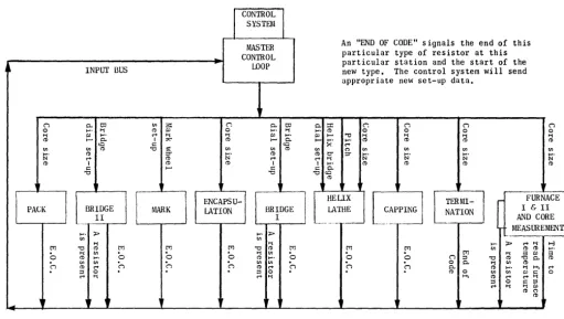
Automated Line Operation
A short description of the Automated Deposited Carbon Resistor Line follows (see Figure 1):
Blank ceramic cores are fed into the appropriate Coating Furnace. The Control System sends the proper core size to the proper Furnace.
The Coating Zone of each Furnace is kept in excess of 2000° F by a Control System Loop. Methane gas is in-troduced into the Coating Zone (of the particular furnace in use at this time) and is broken down, or "cracked" by the high temperature. This results in a deposition of crystalline carbon on the ceramic cores. (The ceramic cores are sequentially fed through the Furnace-each pushing the one ahead-on rotating ceramic rods to insure an even carbon coat.)
As the cores come out of the Coating Furnace, they are cooled in a water jacket to about or below room tempera-ture. The cores then pass through the core Measurement Station. Upon receiving a resistor, this station sends a "Resistor Present" signal to the, Control System. Within about three seconds, the Control System will put in the voltage value (in voltage form) of this resistor, convert it to binary, analyze it, record it, and send a Pass or Reject signal to the station. The other two measurement stations, Bridges I and II, also operate approximately like this one. The limits of the Pass/Reject band at the Core
Measure-ment Station are ± 5% around Nominal-this Nominal is
not the final desired nominal value of resistance (this is set at the Final Measurement Station), but is a value lower than the final value desired. We will see why when we get to the Helix Lathe.
The information from this Core IVfeasurement Station is also used in a control loop, Figure 3, to maintain the product around the desired nominal value by control of the methane gas flow into the Furnace and the amount of the Core Drive, which determines the speed of the cores through the Furnace. Statistical Quality Control (SQC)
X
(average) alld R (range) chart methods are used bythe Control System Computer to determine when to make a correctioll.
The core is then transported through a plastic tube by air pressure to the Termination Machine where a thin layer
12
of gold is applied to a small band on each end of the core. This band will act as a bond between the cap and the carbon coat.
The core is now transported, again through a tube, to the Capping Machine. The Capping Machine press-fits a gold-plated cap, complete with leads, onto each end of the core
(over each gold band). The machine checks each core for missing leads and caps.
The cores now are put onto "pallets"-one core to a pallet. The pallets are on a conveyor line which will carry the cores along the remainder of the line.
The capped cores now go into the Helixing Lathe. This lathe cuts a spiral groove, through the carbon, around the core to bring the resistance value up to the value on the Helix Lathe Bridge (or, just Helix Bridge). This value is somewhat near the final value expected-the Helix Bridge has been offset by the Control System to compensate for overshoot and heat during spiraling, drift during the re-mainder of the line, etc., (and, of course, how the Control System is operating today).
The Spiralled Resistor now is carried by pallet into the Measurement Station after Helix (Bridge I). Bridge I is an ordinary Wheatstone bridge arranged for a.utomatic operation. Instead of letting a galvanometer indicate the imbalance voltage, however, the voltage is fed into the Control System, converted to a binary number, and used in the control loop. The nomina I, set on the dials of Bridge I, is the required final value of the resistor-the nominal value in the Computer's memory will be modified very slightly-less than 1 %-to compensate for drift during Encapsulation, etc.,-up to the Final Measurement Station.
The limits of Bridge I are ± 1% of the adjusted nominal
held in the Computer's memory. Pass/Reject signals are sent from the Control System to Bridge I.
The data from Bridge I is also used by the Control Sys-tem in a closed loop to control the Helix Lathe to produce product around the desired nominal value held in the Computer's memory by adjusting the Helix Bridge. SQC
X
and R chart methods are used by the Control System todetermine when to make a correction.
The spiralled resistors are now carried by the pallets and the conveyor system into the Encapsulation Machines. Here the ceramic core is encapsulated in a shell of .Epoxy Plastic. This combination passes through a curing oven for about 17 minutes and then is placed on another pallet at the exit of the Encapsulation Machine.
The encapsulated resistor is then passed into the Leak Detector. This Detector uses hot water and ten photo-electric cells to search for any bubbles caused by any hole in the epoxy shell. Any leakers are automatically rejected. The Control System is not tied into this machine.
The resistors are air-dried and fed into the Marking Machine. The Marking Machine is set up for each code or type of resistors by the Control System. This machine is an offset printer with four type wheels in turret form. Different combinations of these wheels are selected by the Control System. After Marking, the Resistors go into the Final Measurement Station. Bridge II is set up by the Con-trol System to the exact required final value. The Pass/
Reject Limits are ± 1 % of this final value. Information
"We use Computer Audiotape
in all phases of
our computer operation"
... *,..
.
.
!~i
says Mr. Lou/s L. Hodge, Director of Data Process/ng Operat/ons for \ ..
:t
...
~~:Government Employees Insurance Company, Chevy Chase, Maryland "'~q.~
GEICO is one of the leading auto insurers in the United States. As a result,
our large computer section is used to keep the individual files on almost a
million policyholders constantly up to date, as well as to process thousands of claims
weekly. Computer Audiotape is active in all phases of these operations. We have purchased
close to 1,000 reels in less than a year. We prefer Computer Audiotape for a number of
reasons. First-and most important-its quality has been very good. Second,
the price is right. And third, the service we get is most satisfactory.
GEICO is Just one of the many prominent cOnl1JallieS thal
CO/lsist-ently specify Computer Audiotape. They kllOlV that each reel is
manufactured with extreme care. They know that each reel is 100% checked to insure that every "bit" reproduces properly. Try Com-puter Audiotape in your own operation. It's available in a variety
of lengths, in bit densities oj 200, 556 and 800, in standard and heavy duty types. And consider Audio's new Extra Length Com-puter Audiotape which offers 50% more tape on the same size reel. Write for complete illformation to Alldio J)cviccs, Dept. CA.
AUDIO DEVICES, INC., 444 Madison Avenue, New York 22, Now Yorl\
being packed is sent by the Control System. The Packing Machine pa.cks the resistors edge-wise in blocks of Styro-foam-IO or 15 (depending on watt size) per block. The blocks are loaded on a tray for easy storage. The
produc-tion line is programmed to produce one
Y4
orY2
wattresistor every three seconds or one 1 or 2 watt resistor every six seconds.
Duties of the Control System
The Control System has seven jobs. These are:
1. To "program" the types or codes of resistors in the line a.t once by recognizing when the last resistor of a given type has passed a given machine and then sending in-formation to that machine to set it up for the next type to be made.
2. To measure the temperature at Furnace I and II and to send appropriate corrections to keep the temperature at some discrete va1.ue in excess of 2000° F.
3. To compensate for a change in resistance during en-capsulation by examining the resistors measured by the Final Measurement Station (Bridge II) and adjusting the Nominal Value expected at the Measurement Sta-tion after the Helix Lathe (Bridge I).
4. To give a 100% Pass/Reject inspection to each resistor at the:
A. Core Inspection Station (after the Coating Furnace) B. Measurement Station after the Helix Lathe (Bridge I) C. Final Measurement Station (Bridge II)
x
2
3 4
5
6
7
8
9
10 11 12 13
The Pass/Reject limits are ± 5% at the Core Measurement
Station and ± 1
%
at the other two stations.5. To automatically account for shrinkage by adjusting the number of cores expected out of the furnace to produce the required number at the end of the line (Packing). 6. To produce a typed sheet at the end of each day's run
showing the statistics of that run.
7. To use Statistical Quality Control Methods (X & R
charts) to control
A. The value of the cores coming out of the furnace by controlling the amount of methane in the furnace and the speed of the cores through the furnace. B. The value of the resistor coming out of the Helix
Lathe by adjusting the dials of the Helix Bridge.
Method
o·f
'Control
A useful way to control a process or machine is to
examine the output of this machine or pro~ss by the use
of Statistical Quality Control
X
and R Charts (also calledaverage and range charts).* An example of an
X
and RChart is shown in Figure 2.
Data is taken from the process to he controlled in random
samples of N equal to 2, 5, or 10 items. The measurement
in each sample is Xl, X2, Xi! .... We shall here use N
=
5. The definitions of other symbols are:X
is the average of 5 pieces of data orX
=
.. E. L. Grant, "Statistical Quality Control," 2nd edition, McGraw· Hill Publishing Co., New York.
UCLX
ZONE A
8
C
C'
8'
A'
LCLX
X
CHART
-R
2 -3-
45
-6-
78
-9
-101
1121"3
-R CHA-RT
FIG. 2
UCLR
A
8
C
C'
8'
AI
PHOTO COURTESY OF LOCKHEED CORP. © AMPEX CORP. 1963
"'~:~~'Y~~'~~~'~~~'~==~~
Now: who's got news for everyone with an IBM computer system?
AMPEX
The news is inside an eight page booklet. It
tells the what, the why and the how of Ampex
computer tape -the tape that provides superior
performance in I BM computer systems. If you
think you might find the booklet helpful, just
write and ask for it. Also, we'll put your name
on our mailing list and regularly send you our
informative periodical, "Tape Trends." It's a
good way to keep abreast of the fast changing
tape techrlology. In it, the latest tape
develop-ments are clearly explained by Ampex tape
COMPUTERS and AUTOMATION for February, 1964
experts-the same experts who
application-engineer Ampex tape to your system. This is just
one of the many ways we assist you in obtaining
maximum system efficiency. In addition to
en-gineering the tape to your system, Ampex
digi-tally checks each reel from end to end, and
guarantees its performance. Write for free
booklet, "Ampex Tape for IBM Computers,"
and your copies of "Tape Trends." Ampex
Corporation, Redwood City, California. Sales
and service engineers throughout the world.
Circle No. 11 on Readers Stlrvice Card
(Xl
+
X 2+
Xa+
X4+
X5) 5X
is the average of the X's orX
=
(Xl
+
X2+ .... +
XI)/i where i is the num-ber of samplesR is the range or spread of a sample of N pieces of
data, i.e.,
R
=
Xmax - Xmin, the largest X in the samplethe smallest X in the sample.
R is the average of the R's or
R
=
(Rl
+
R2 . . . .+
RI)/iThe Upper (UCL) and Lower (LCL) Control Limits are determined as follows:
UCLX
=
~
+
A2RLCLX
=
X -
A2RUCLR
=
D4RLCLR
=
DaRA2, D4, and Ds are determined by N from tables. For N
=
5,A2
=
0.577,Da
=
0,D4
=
2.115In our system, however,
X
is the desired nominal to beproduced NOT the average of the X's and
R
is the estimatedor observed spread or "range" of the machine in question
and NOT the average of the R's. And as data
(measure-CONTROL SYSTEM
INPUT I
&
SQC LOOP I
ments) are entering the control system constantly, the chart
limits, UCLX, LCLX, etc., must be calculated first based on
the given
X
and R, and then the incoming X's and R'splotted around
X.
As each X is plotted, the resulting pattern is checked.
If this pattern is "statistically probable," the process or
machine is said to be "in control"; if this pattern is not probable, the .process is said to be "out of control" and therefore, some action must be taken to try to bring the process back within control.
The tests used to check the pattern are sometimes called "non-parametric data tests" or simply "data tests." These
tests are applied to each half of each chart. For N equal to
5, if any of the following conditions are met, an improbable
pattern is said to exist:
1. If any single point falls outside of the control limits.
(An example is Point 1 in the
X
chart in Figure 2.)2. If any two. out of any three sequential points fall
in Zone A or above (Point 4 and Point 6).
3. If any four out of any five sequential points fall
in Zone B or above (Point 4, 6, 7, 8).
4. If any eight sequential points fall in Zone C or
above (Point 6 to 13).
The occurrence of the last point in these conditions identifies the pattern as statistically improbable.
T!:ese tests would also .be applied to the lower half of
the X chart if the X in question fell there, and also to both
halves of the R chart.
CON:rROL SPEED
OF TO
TERMINATION MACHINE
CONTRO L METHANE
BINARY V LVE
. CORES THROUGH FURNACE
16
PASS
FLOW
REJECT
\
/
REJECT BiN
COATING FURNACE
FURNACE - CONTROL SYSTEM - METHANE, COR8 DRIVE
CLOSED LOOP
FI G. 3
CORE
DRIVE ..
I
CONTROL SYSTEMI
MASTER An "END OF CODE" signals the end of this
..
CONTROL particular type of resistor at this~ INPUT BUS -,.. WOP particular station and the start of the
new type. The control system will send appropriate new set-up data.
(""J 0.. 1:0 til a: r. 0.. 1:0 0.. ::t: r. (""J (""J (""J
0 1-'- '"l ~
'"
0 1-'- '"l 1-'- ~ 0 0 0 0'"l
'"
1-'- c-+ '"l '"l'"
1-'-'"
... "tI '"l '"l '"l '"l~ ... 0.. I ::>;" ~ ... 0.. ... ~- 1-'- ~ ~ ~ ~
to s:: to c-+
til til ~ "0 :g til til ~ til (') til til til til
1-'- ~ :::- 1-'- ~ ~ 0" :::- 1-'- 1-'- 1-'-
1-'-N c-+ ~ N c-+ c-+ '"l N N N N
~ I ~ ~ I I 1-'- ~ ~ ~ ~
s:: ... s:: s:: 0..
"0 "0 "0 to
~
...---TERMI- r- FURNACE
I
II
BR~~GE
I
I
f
ENCApSU-11
l [
llliUX CAPPING!1
PACK MARK LATION BRiDGE ___
~_T~~
NATION I & IIc-._ .. _
~
c--. AND COREI MEASUREMENT
1-'- ~ 1-'- ~
-til til
1Il "0 '"l ~ 1Il 1Il 1Il "0 '"l ~ 1Il 1Il 1Il 1-'-til ~ c-+ ~ ~ '"l t-3
1-'-0
'"l til0 0
0
'"l til0
0
1Il '"l3 '" 3 ~ 1-'- ~ 1-'- 0 (""J ::s "0 ~ "00.. ~
(""J til ~ c-+ til
n
n
(""J ~ til c-+ til (""Jn
(""J 0 0.. 0.. '"l ~ til 1-'- ~ '"l H, c-+::s 0 ::s 0 ~ 0 til til '" s:: 0
c-+ '"l c-+ '"l H, ~ c-+ c-+ '"l
::s 0 s:: ::s
c-+ '"l '"l '"
~ (')
I,
" ir r ~•
II-MISCELLANEOUS AND SET-UP LOOPS
FIG. 4
The Program
The LGl'-30 Computer is programmed to p~rform the
"uon-parametric data tests" necessary to analyze SQC
X
amI R charts.Four computer memory "words" are used for an
X
chart~nd four for the R cha.rt. Let us pay attention to just the X chart-the R chart will be handled in the same way.
Furthermore, let us consider only the upper half of the
X
chart.
Two of the four words for the
X
chart are used for theupper half of the
X
chart. One of these words is calledthe "Pattern" ~ord-this holds the pattern of up-to the last 8 points (X's) which have been plotted. (Blanks or zeros are plotted in this word for those points falling in the lower half of the chart). The other word is called the
"Su~" word-this holds the sum or total number of points which have fallen in the A Zone or above, in the B Zone or above, and/or the C Zone or above. Each of these words is divided (by the program) into three separate sections for Zones A, B, and C, respectively. Tests for an im-probable pattern are made beginning in the Zone in which the point fell and continuing Zone by Zone to the C Zone. All numbers are in the binary system.
Corrections
When the Computer determines that a statistically im-probable pattern exists, a suitable correction factor is
formed and sent to the appropriate machine. If in the
Furnace Control Loop, the correction is sent, first to the Core Drive (speed control); if the error is too large to be corrected by the speed control, the correction is sent to Methane Control and the speed control returned to
mid-range. If in the Helix Lathe Control Loop, the correction
is sent to the Helix Bridge Dials.
COMPUTERS and AUTOMATION for February, 1964
The correction sent is NOT based on how far the
X
causing the failure is from the Center Line, but is based on the average of a certain number of previous X's. For instance, in Figure 2, the corrcction would not be based on Point 8 alone, hut possihly on the average of points 1 thru 8.
If, p~r chance, the
X
chart ANI) the R chart fail (or show improhahle patterns) at the same" time, the computer isprograllllllcd to consider that this
X
and R representim-proper data or "sports_" Thl' fOlIlputer will then disregard these "sports" and send no wrrection. Fortunately, this condition occurs very rarely in norma.l operation, only when something is happening- to the process that warrants
im-mediate human attention (perish the thought!) .
After a correction is sent to a particular machine, the computer program inhibits further corrections being com-puted for a certain length of time so that the parts made under the old setting may pass by the measurement station
and the parts made under the new corrections may have
passed long enough for a valid chart to have been plotted.
O'peration
The complete automated production facility was first operated in its entirety in 1960. Since then continued re-finements have been made in the control equipment in the computer program and in the highly complex array of machinery designed and developed especially for this appli-cation.
The combined efforts of the engineering team resulted in extremely encouraging- perforJllance for the production line as a whole, anel particularly for the control concept. Further development should lIIake possihle its application to an entire family of manufacturing facilities.
[image:13.624.60.571.46.335.2]METHODS OF EVALUATING
COMPUTER SYSTEMS PERFORMANCE
This article begins a series of important reference reports on computing equipment and techniques. The author describes a reference service which evalu-ates computer system performance, and discusses the method, with examples, of achieving this evaluation. Further articles in the series will examine decision tables; input/output equipment, high speed printers, and optical character recognition equipment.
The Problem of Comparison and Evaluation
The prospective computer user must progress through fifteen painstaking steps in making an installation of elec-tronic data processing equipment:
1. Analyze present system and needs
2. Establish requirements
3. Choose initial (or next) applications 4. Design system
5. Determine approximate time on possible computers 6. Time the best candidate computer systems in detail 7. Check availability
8. Analyze software for efficiency, availability, and ease of use
9. Evaluate costs, for growth and compatibility 10. Consider non-technical aspects
11. Select "best" computer system and configuration 12. Contract for system
13. Program the system
14. Plan conversion and convert 15. Plan operation and operate
Norman Statland
Manager} Business Information Systems
Auerbach Corp.
Philadelphia} Pa.
Assuming that he has worked his way through the first fo'ur steps, he is next faced with the task of reducing the field of selection to a group of the computer systems that seem most likely to provide an economic and effective solution to his problem. By the time he has narrowed his range of interest down to perhaps five computers and is ready to begin a detailed analysis, he is probably faced with a six-foot shelf of assorted manuals on the characteristics of the pertinent systems and of the software packages the equipment manufacturers will furnish.
This is only the beginning of his problem. All he really has now is a collection of material that is not very suitable for his purposes for either of two reasons: either the
material presents carefully selected data reflecting th~
RUN DEFINITION FOR FILE PROCESSING PROBLEM
PROCESSOR
Figure 1
COMPUTERS and AUTOMATION for February, 1964
UNIVAC III SYSTEM PERFORMANCE
WORKSHEET OAT A TABLE 1
Configuration
Worksheet Item VIII B ,Reference
III VI VII A
C. P. Blocked Unblocked Details Details
.4 Unit of measure (word)
Std. routines 4,990t 4,990 t 4,990t 4,183t 4,990t
Fbted 0 0 0 0 0
3 (Blocks 1 to 23) 162 162 162 162 162
Standard 4:200.1151
Problem A 6 (Blocks 24 to 48) 410 420 420 420 420 Space
Files 1,344 1,344 1,344 2,400 1,344 Working 100 100 100 100 100 Total 7,016 7,016 7,016 7,265 7,016
t Includes 3,000 words for the Executive routines.
[image:15.634.66.570.59.295.2]©
1963 Auerbach Corporation and Info, Inc.Figure 2
emphasis chosen by the manufacturers' eager sales depart-ments; or the material consists of detailed system, program· ming, and engineering information in various formats and terminologies, in quantity much greater than he can easily use. Somewhere in tlUs glut of material are the equipment characteristics and the performance information important to him, but in order to find them, he must weed out the purely sales material and he must decipher the terminology that varies from manufacturer to manufacturer.
Having got this far, if he is not discouraged, he is ready to try to compare the specifications of the various systems and evaluate their performance. Now he makes the dis-covery that each manufacturer quotes performance figures on entirely different bases. In order to obtain comparable figures, he must make complex interpretations. Once this is done, he is finally ready for step five: measuring each computing system against the jobs he will require it to do.
A Solution
In order to save the prospective user much of this
pain-staking work and to get him . through steps 5 to 15 in a
reasonable amount of time and for a reasonable amount of money, the Auerbach Corporation developed Standard EDP
Reports two years ago. As a technical-services organization
specializing in the design and development of data and information systems, the company was frequently asked to compile detailed reports comparing various features of different computer systems. Out of this work grew an in-terest in the problem of generating standardized compari-sons of computer performance. These standardized com-parisons from system to system could be generally applied to the problem of selecting the system most suitable for a particular set of applications. As a result of the company's res·earch, techniques were developed to generate com
para-COMPUTERS and AUTOMATION for February, 1964
tive measurements; and these techniques became the basis for a published reference service useful to both current and potential computer users, Standard EDP Reports.
In April 1962, the reference service consisted of detailed reports on the characteristics of 7 commercially available systems. Currently, it consists of six volumes covering 50 general-purpose digital computer' systems produced in the United States.
Computer-S,ystem Reports
The computer-system reports describe, in standard form and from the user's point of view, all the characteristics of each included computer system. Each computer system re-port is divided into the following sections:
1. Introduction: A summary of the system's
character-istics and features, with particular emphasis upon its strengths and weaknesses relative to competi-tive systems.
2. Data Structure: How the system represents basic data units.
3. Internal Storage: The size, speed, and characteristics of each available type of data storage unit (core, thin-film, disc, drum, etc.).
4. Central Processor: A user-oriented specification of the capabilities of the processor, including opera-tions performed, special featllres, and times
re-quired to perform standard tasks such as addition
for five-digit llumhers.
5. Illput-Output Units: Specifications of each of the peripheral units available with the system, includ-ing basic speeds, error checks, compatibility of the external storage medium with other systems, etc.
6. System Configuration: Diagrams illustrating the num-ber of typical equipment configurations, includ-ing inter-connection restrictions and component rentals.
7. Simultaneous Operations: A detailed description of the system's capabilities to reduce total job times by performing more than one operation at a time. 8. Physical Characteristics: A summary of the charac-teristics pertinent to physical installation prob-lems.
9. Price Data: Rental, purchase and maintenance costs for each system component.
Software
The computer-system reports also contain sections de-voted to description of the following software elements:
1. Source Languages: A description of the scope and
features of each of the programming languages available for use with the system (COBOL, FORTRAN, assembly languages, etc.).
2. Translators: An analysis of each of the programming packages that translate source languages to
ma-chine langu~ge, including their features,
per-formance, and availability.
3. Operating Systems: A review of the standard routines and conventions available to assist in the sequenc-ing of runs, error detection and correction, and other operating problems.
Measurements of Olver-All Performance on
Bench-Mark Tasks
In addition, the computer-system report also provides measurements of the system's over-all performance in both data-processing and scientific applications. These are based upon typical but precisely defined bench-mark tasks, such as: file processing; sorting; matrix inversion; statistical data processing; and mathematical calculations. Each task is specified by detailed descriptions, parameters and flow charts.
Each computer system is measured at three levels: basic central-processor operations; operation of individual de-vices; and operation of particular system configurations. The fundamental performance specifications are established for each unit of the system; from them, times are developed for performing elementary tasks on each unit. These task times for the individual units are then combined to obtain times for sets of units working together in specific configura-tions. One of these bench-mark problems is file-updating. Figure 1 is a run diagram of the problem in an elementary form. A master file needs to be read in and updated. The detail file contains information for updating the master file. As items in the detail file qlUse activity, reports are gener-ated.
Two basic rules are followed in measuring computer performance on bench-mark tasks. First, the external spec-ifications of the job (i.e., the input and output data and the required results) are specified precisely and in the way that suits the user; the programmed computer system is expected to adapt and conform to these requirements. Sec-ond, although the computer system must conform to the specifications of what is to be done, how it is done is left flexible so that full advantage can be taken of the specific capabilities of each system.
Accordingly, the format and contents of the detail file and the report file are specified minutely, and the contents of the master file are also specified. However, the actual field allocation and editing techniques are chosen to portray each individual system in its best light.
20
Variables
In order to cover a variety of situations that users may face, a number of variables are established for the task. These problem variables fall into three groups: record size; computation volume; and activity factor. Other parameters of course are important to the user: basic speeds, optional facilities, storage volume, simultaneous operations, and the use of off-line facilities. These however are delimited by the system configuration being examined.
In order to produce truly comparable measures of the performance of competitive systems, criteria have been established for a set of typical configurations, which are match"ed as closely as possible from system to system.
Processing Times
The basic ,times computed for a task fall into three classes: input-output times per block for each individual unit; processor delays caused by input-output operations; a.nd central-processor computation time.
Computation time is subdivided, in turn, into three types: the time to process one record from the master file; the time to process the activity caused by one detail record; and the time for the "housekeeping" necessary for moving each block of the master file.
After these times have been individually derived, they are then combined to suit the problem and configuration parameters. The results are presented as graphs which show the time required to process 10,000 records of the master file.
Uses of this Evaluation Technique
These techniques have been systematically applied to evaluate most of the major computer systems produced in the United States. The result is a collection of objective data that helps: a prospective computer user, to make more knowledgeable equipment decisions at less cost; a current computer user, to evaluate configuration changes; and both kinds of users, to analyze software efficiency, availability, ease of use, and the practica lity of changes in system opera--tion.
Big or Little Runs
Let's take a look, for example, at the frequent problem of deciding whether to collsolidate all aspects of a program into a single run, or to divide the program into several runs.
The governing factor affecting this decision is the utiliza-tion of memory space.
A quick guide to the amount of memory space required for one of the bench-mark problems is shown in Figure 2. For the UNIVAC III it is seen that at least 7,016 words of storage will be necessary. The user can measure his pro-gram in terms of the additional degree of complexity that will require additional instructions and deduce whether the contemplated run will fit within the core storage size ava.il-able.
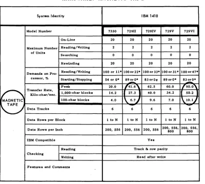
Another typical question is: will faster tape units enable an IBM 1410 currently equipped with 729 II tape units to handle a file-processing job in less time?
Figure 3, a comparison chart from the computer-system report on the IBM 1410, shows there are five different tape units ava.ilable for the 1410 system, with peak speeds
rang-ing from 20,000 to 90,000 characters per second. Going
from the 729 II to the 729 VI appears to increase the tape speed from 14,600 to 90,000 characters per second, for a 120% increase. The chart shows not only the apparent
increase in speed but also the effective increase. If the
block size is 1,000 characters, effective speed really increases from 27,000 to 50,000 characters per second, for an 85% increase and 46% saving. If the block size is only 100
..
UWhy we chose the NCR 315 Computer with CRAM."
"Our choice of the NCR 315 Computer with CRAM (Card Random Access Memory) resulted from a 31/ 2·year evaluation study. In each case, the factors pointed to the 315 with CRAM as the computer best suited to our needs.
"Our reasons for going electronic were twofold: 1) to gain the benefits of
- STATE OF NEW MEXICO, Santa Fe, New Mexico
better management control, including fiscal control of the state's resources; and 2) to keep pace with the growth and the economic progress of our state.
"With the 315 we a re a ble to react quickly to changing financial condi· tions. We have mo re ti mely and meaningful data upon which to base
management decisions. We have an expansible system - one that is cap· able of growing as we grow ... and we are in a much better position to fulfill our fiscal responsibilities to the citi· zens of New Mexico."
Jack M. Campbell
Governor
State of New Mexico
NCR PROVIDES TOTAL SYSTEMS - FROM ORIGINAL ENTRY TO FINAL
REPORT-THROUGH ACCOUNTING MACHINES. CASH REGISTERS OR ADDING MACHINES. AND DATA PROCESSING
The National Cash Register Co. • 1,133 offices in 120 countries • 80 years of helping business save money
INlclRI
COMPARISON OF SMALL TO MEDIUM GENERAL PURPOSE SYSTEMS
HARDWARE: MAGNETIC TAPE
System Identity IBM 1410
Model Number
I
7330 729II 729IV 729V 729VIOn-Line 20 20 20 20 20
Maximum Number Re ading/Wri ting 2 2 2 2 2 of Units
Searching 0 0 0 0 0
Rewinding 20 20 20 20 20
Demands on Pro- Reading/Writing 100 or 11. 100 or 22. 100 or 33. 100 or 31. 1000r47· cessor, '70 Starting/Stopping 54 or O. 89 orO. 830rO¢ 890rO· 83 orO.
-
--Peak 20.0 (41.6' 62.5 60.0
r
9O . 0,~
Transfer Rate,1,000-char blocks 14.2
,
27.3I
40.0 34.2If
50.2I
Kilo-char/sec.laO-char blocks 4.0 \ 6 . 7 . / 9.6 7.0
\10.lj
~
Data Tracks 6-
6 6 6-
6Data Rows per Block 1 to N 1 to N 1 to N 1 to N 1 to N
Data Rows per Inch 200, 556 200, 556 200, 556 200, 556, 200, 556, 800 800
IBM Compatible Yes
Reading Track & row parity Checking
Writing Read after write
Features and Comments
• With optional equipment.
[image:18.615.95.496.65.425.2]©
1963 Auerbach Corporation and Info, Inc.Figure 3
acters, the increase is from 6,700 to 10,000 characters per second, an increase of only 50% and savings of only 33%. On a >tape-limited job lasting six hours a day with the present tape units, the potential saving is 2.8 hours for I,OOO-character blocks and 2.0 hours for 100-character blocks.
The price data section of the computer-system report
shows that the rental for the IBl\J 1410 will increase $250
per month for each tape unit upgraded from a 729 II to a 729 VI.
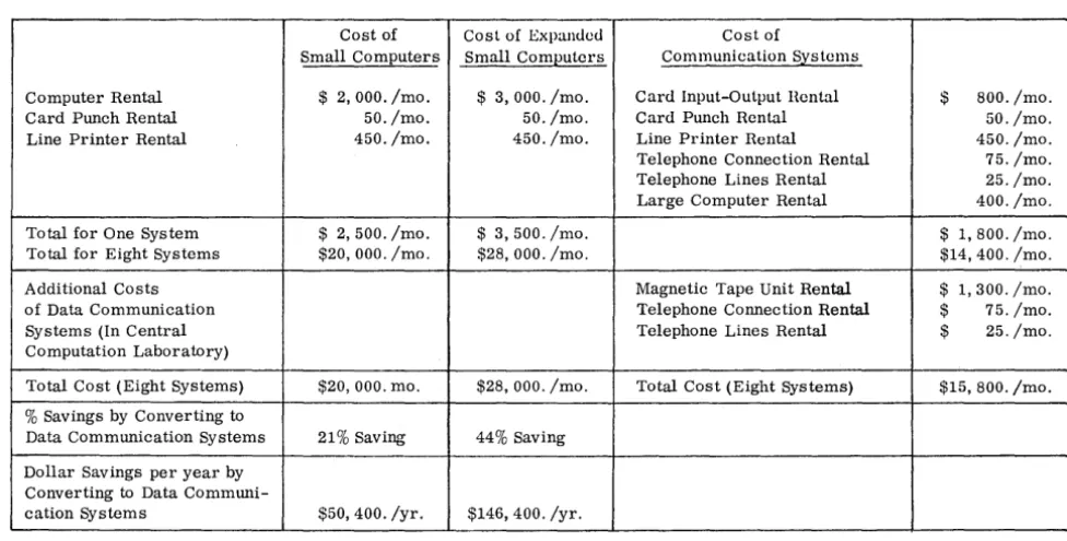
Other data in the computer-system report shows that the same controller can handle the 729 tape drive, Models II, IV, V, and VI in any -combination. Therefore, it would not be necessary to change controllers and it is not neces-sary to change all the tape units. The comparison-charts section of the report shows that the typical monthly rental for a six-tape IBM 1410 installation is $12,930.00. Based on all this information, the user can easily calculate the increased cost and see whether the resulting savings in job time are justified (see the calculation in Figure 4).
Software Evaluations
In the computer-system reports, special emphasis is placed upon the key features of software that affect
per-22
formance, versatility, and use. The common progra.mming languages as used on a specific computer, such as FORTRAN and COBOL, are described in terms of how they differ from some standard. For example, Figure 5 shows information provided on the COBOL source
lan-Rental 6-tape 1410 system:
Extra rental for two Model VI over two Model II:
Total time of job: .
EXAMPLE
New time (50% real increase in speed): Saving: .
Value of time saved: Extra rental: .
$12,930 per month
= $82 per hour
$ 500 per month 4% increase 6 hrs per day 33% decrease in time
2 hrs per day 25% of a day
4
'Iguage for the IBM 1401. This clearly shows the deviation from the required COBOL specifica tions, and enables the user to quickly determine the degree of compatibility be-tween two implementations. In cases where several versions of one translator are available, the system report on each translator shows the general structure of the translator, the translation times, the effects that variolls configurations have upon the translator, and the efficiencies, with respect to both execution time and memory space, of the resulting . object programs.
IBM 1401
Procedure Division:
• The REEL option of the CLOSE verb, which pro-vides for the closing of a reel prior to its normal end, is deferred.
• The EXAMINE verb and TALLY register, which make it possible to replace and/or count the nmn-ber of occurrences of a specified character in a
data item, are deferred.
t
• A given file cannot be processed both as an input file and as an output file in the same Program.
• A literal used after the STOP verb must be
nwner-ical and less than four digits in length.
t
t
Deficiency appUes only to the 12K-16K versionof 1401 COBOL.
Extensions to COBOL
61: . . . , none. (The SORT verb and
Report Writer facility of Extended COBOL-61 are Q.ot provided. )
Figure 5
For prospective users interested in measuring the per· formance of system choices or for the user interested in maximum utilization of system software, the computer-system reports list and describe all the major utility routines available, noting the major omissions and reporting all key criteria. The system-performance section shows the operation times for the routines, and sections of the com-parison charts compare operation times from system to system for various standard configurations. The operating systems provided by the manufacturer or independent users are also described in detail.
These computer-system reports do not, of course, remove from the systems-analyst the burden involved in selecting computer equipment or in improving system operations. What they do do, however, is to provide him with a more objective and factual basis than has previously been avail-able for making computer-system decisions. The compre-hensive data provided are applicable to all classes of appli-cations-statistical, mathematical, scientific, and commercial -and furnish the prospective or actual computer user with a set of basic, standardized bench-marks that can be readily adapted to fit his particular situation.
More detailed information on the cost and availability of Standard EDP Reports can be obtained from the publisher, Info, Inc. (a
sub-sidiary of the Auerbach Corp.), 1634 Arch Street, Philadelphi,a 3, Pa., or by circling No.3 on the Reader Service Card.
COMPUTERS and AUTOMATION for February, 1964
Memo To Controllers and Data Processing Managers:
#
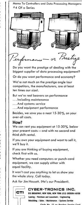
4 Of a SeriesDo you want the prestige of dealing with the biggest supplier of data processing equipment? Or do you want performance and economy? We're not much on the prestige angle (our competitors, the manufacturers, are at least ten times our size),
But we're real beavers on performance · .. Including maintenance
· .. And systems service
· .. And equipment performance
Besides, we save you a neat 15-30 % on your
over-all costs.
How?
We can rent you equipment at 15-300
/ 0 below
your present costs - and with no second and third shift rental.
If you own your equipment and want to sell it, we'll buy it.
If you are thinking of buying equipment, check first with us.
Whether you need computers or punch-card equipment, we can supply either with equal facility.
It won't cost you anything to let us show you the whole story. Call today.
Ask for Jim Hassett. (He's our President),
CYBER-TRCNICS INC.
915 BROADWAY, NEW YORK, NEW YORK (212) OREGON 4-9150 LeaSing / Purchase and Leaseback / Engineering
Rebuilding / Sales / Maintenance / Systems Service
[image:19.615.305.585.44.742.2]"COMPUTERS, AUTOMATION, AND EMPLOYMENT" - DISCUSSION
I. To the Editor from W. H. Mandel New York, N.Y.
Regarding the widespread and well-meant demand for full employment, if training or retraining alone cannot provide people with jobs, as you emphasize in your November editorial "Computers, Automation, and Employment", isn't it equally futile, in the long run, to attempt to create conventional jobs in the face of a secular trend eliminating them?
Can we rightly compare employment figures for West Germany and Russia with those for the United 'States as long as the former countries benefit (in
this respect) from the impetus of reconstruction (Germany) or an intermediate stage of economic de-velopment (Russia), and the delayed advent of automation?
The problem for this country ~ppears to be the
novel one of distributing equitably among the entire population the abundant product of a relatively small
labor force, witho~t undue shock to tradition. This
involves, in your image, the surrender of our "sacred cows", screaming eagles, etc.: the many worshippers of these animals may lapse, but not lightly.
For instance, one sacred cow still held dear even by some of those who have disavowed other fet-ishes is the notion that every able-bodied head-of-household between the ages of 20 and 65, roughly, should be "gainfully employed" in order to subsist. Automation will soon render this faith untenable, but not without a severe wrench.
As a first approximation t~ a solution, the
mUltiple billIons 01 dollars now marked, as you
mention, for a marginally rewarding voyage to the moon, might instead expand the Social Security sys-tem so as to lower retirement-eligible ages and in-crease pensions to levels at which middle-aged with-drawals from the industrial labor market would bring the number of available jobs into approximate bal-ance with the number of displaced workers and youngsters seek i IIlJ pai d emp loyment .
Retraininn and re-education in this context would make sense, wouldn't you say, both for the working-hired and especially for the working-retired freed from the curse of the cash requirement?
II. From the Editor
As long as 1/3 or 1/4 of the members of a so-ciety are deprived of an adequate standard of living
which they would surely acquire i f they had more
motll~y, there is usefu I work to be done. The prob-lem that has to be faced up to is providing goods and s(~rvices to people who have not "earned" them,
becaus(~ a scarci ty society has changed into a society of abundance. The idea of lowering retire-ment aUes to balance approximately the number of un-employed certainly has some merits.
24
c&a
READERS' & EDITOR'S FORUM
ADVERTISING, PUBLICITY RELEASES, AND
INFORM~TION WORTH PUBLISHING I. From Charles R. Cross
Long Beach, Calif.
When I received the October issue of "Compu-ters and Automation", with the first glances through the magazine I noted the article "The Printing of Advertising as Publicity Releases". Upon closer examination, I was distressed to find an attitude by an executive such as was expressed by Mr. Ludka.
While mistakes may happen, th~y can be corrected.
This is evidenced in your return letter to him. What is distasteful is the presumptuous stance
taken. It appears that they wi sh thei r "biggest in
our history" budget to be a club with which they may mold opinions, and that all should grovel for a share of their dollars.
It is good to see'that there are those who have formed solid principles and will refuse to have them abridged. The fact that your publication is above this type of pressure is the reason that it does contain the information which is "factual, useful, and understandable", rather than what those who have a financial stake want us to see. Continue to pur-sue this policy of self control, for it is the way to prohibit the spread of the tyranny of controlled information.
II. From R. W. Olmstead Lnng Branch, N.J.
The exchange of letters between yourself and Mr. Ludka, noted in the pages of the October 1963 issue of Computers and Automation, has evoked from me a reaction of some amusement, some sympathy, and a very high degree of respect for you and Computers and Automation in the editorial standards you have set for your magazine and the courage with which you defend them.
As an Advertising Manager, I have many times been frustrated when certain books have failed to give appropriate attention to the product publicity generated by my department. However, whenever this failure to pick up my publicity has been the result of a consistently high editorial policy, the result has been to increase my respect for the magazine which defended such policy. I, personally, deplore the short-sighted attitude displayed by Mr. Ludka and I certainly congratulate you on sticking to your "edi torial guns". I shall 'probably tangle with you personally in the future should you fail to pick up some publicity on my products, but I will be ready to respect your position so long as it follows the clean and clear principle you have demonstrated to date. Similarly, I shall not allow such disappointments to obstruct the objectivity of my advertising program philosophy.
To get
all1this
with
your
computer tape ...
switch to this!
Soundcraft Computer Tape is engineered to give you improved performance in your computer
installation. To insure absolute coating depth uniformity, Soundcraft "re-faces" the durable
Mylar* base. Micro-plating, an exclusive
(and completely new)
Soundcraft process, produces the
smoothest surface found on any tape today. The result: a long-wearing, shedding,
non-abrasive tape with greatly improved head compliancy-for flawless data recording. Available in
Heavy-Duty and Regular Wear, 100% Pre-Tested at 800 or 556 bits per inch. Write for data.
·DuPont T.M.
Main Ollice: Danbury, Conn •.• New York. Chicago. Los Angeles. Foreign Div.: 25 Warren St., N.Y.C. • Canadian Reps: Vancouver. Toronto. U. K. Reps: Soundcraft Magnetic Ltd.
Circle No. 13 on Readers Service Card
SMALL SCIENTIFIC COMPUTERS
VERSUS
DATA COMMUNICATIONS SYSTEMS
IN A LARGE COMPUTER ENVIRONMENT
Rogcr A . MacGowan
Chicf, Scicntific Digital Branch
Army klissiic Command Computation Center
Redstone A rscna l, Ala.
lVfany large organizations have their organizational seg-ments scattered over a fairly large geographic area, and this presents some problems for efficient digital computer operations. Frequently organizations in this situation have formed a centralized computer laboratory containing one or more large-scale computers and staffed with professional programmers, while at the same time permitting the use of small-scale computers in decentralized locations. In such a situation the very large problems are necessarily run on one of the large-scale computers in the central laboratory, while many small and medium-sized problems are run on the small decentralized computers.
These situations have created considerable interest in the outcome of the competition between small-scale com-puters, on the one hand, and remote input-output devices communicating with large-scale computers, on the other hand. The cost of small-scale computers has been declining rapidly, while simultaneously many computer manufacturers have been carrying out research and development on tele-phone and microwave communication equipment for de-centralized computer input-output. Very recently, several remote input-output devices using data processing trans-mission have become commercially available; therefore, a direct cost comparison of the two differing approaches, at the present state· of -the art, is now possible. As a result, a reappraisal of the over-all computing philosophy is cer-tainly in order for many organizations.
Small Computers vs. Messengers
The average distance of 'lhe computer users'~groups from
the centralized computation laboratory is a critical factor in a study of organizational computing policy. Large-scale computers are inherently much more efficient than smalJ-scale computers, therefore, almost the only reasonable justification for the use of small computers in a large
com-26
puter environment is the more ready availability of the small computer. This implies that the sponsor of the
in-dividual problem must make an inconvenient trip to the
computer center with his small problems, and that a suit-able problem pickup and delivery schedule cannot be ar-ranged, or that turn-around time is excessive on the central, large-scale computers.
In order to achieve ready availability on a small com-puter, it must be assumed that the workload is moderate and that the problems are short, generally requiring less
than thirty minutes each. If the daily workload exceeds
about 5 hours, or a number of problems exceed about thirty minutes each, queues tend to develop and the "ready availability" justifica'lion, which is the sole justification for the small computer, vanishes. Often these queueing prob-lems result in the scheduling of one time period per day for each user of these small computers, again defeating the purpose of the small computers.
Suppose the average travel time from decentralized
10-ca'lions to the central computation laboratory is thirty
minutes or less, and the turn-around time on the large-scale computers is two to three hours. Then it should be possible for the user in the decentralized location to obtain two or perhaps three runs on the large-scale computer per day; . if a reasonable messenger service is established. It is unlikely that more computer runs than this can be obtained on a small computer having a moderate workload and placed in the decentralized location. Therefore, two distinct dis-advantages are apparent in using small computers in such a situation:
(1) An inferior computer is used to process all small and medium-sized problems.
(2) All small and medium-sized problems are solved at far greater expense than necessary.