CDU700
INTELLIGENT
UNIBUS SCS I HOST ADAPTER
~U~CMD
==
ETECHNOLOGY-~~~~~
CDU700
INTELLIGENT
UNIBUS SCSI HOST ADAPTER
CMD TECHNOLOGY, INC.
1 Vanderbilt Irvine, CA 92718
.( 7.14) . 454-0800
CDU-700 Rev 3.5
FCC WARNING
This equipment generates, uses and can radiate ·radio frequency energy, and if not installed and used in accordance with the technical manual, may cause interference to radio communications. It has been tested and found to comply with the limits for a Class A computing device pursuant to Subpart J of Part 15 of Federal Communications Commission (FCC) Rules, which are designed to provide reasonable protection against such interference when
operating in a commercial environment. Operation of this
equipment in a residential area is likely to cause interference in which case the user at his own expense will be required to
take whatever measures may be required to correct the
interference.
Copyright c 1988 CMD Technology
The information in this document is for information purpose and is subject to change without notice.
CHAPTER 1
CHAPTER 2
CHAPTER
3CHAPTER
4CHAPTER 5
APPENDIX
A
APPENDIX
B
APPENDIX
C
APPENDIX
D
'rABLE OF CONTENTS
INTRODUCTION ••••••••••••..•••.••••.•••••••••••. 4
CDU-700 SPECIFICATIONS •••.••••••••••••••••••.•• 5
2.1
Controller Specifications •••••••.••••• 5
INSTAL'LATION ••••.•••..•••.•.•••••••••••.•••••••
63.1 3.1.1
3.1.2
3.1.33.1.4
3.1.53.1.6
3.1.73.1.8
3.2
3.2.13.3
3.4
CDU-700 Jumper Settings •••••••••••••.• 6
CSR Address Selection ••••••••••••••••. 6
SCSI Host Adapter ID Selection ••••••.• 8
SCSI Target ID Selection ••••••..•.•••• 8
SCSI Terminator Power Option ••••.•.•• 10
Tape Mode select ••..••••••••••••••••• 10
Tape Fast Search Option ••••••••.••••. 11
LED Indicators •••••.••••••.•••••••••• 11
Disk Auto Boot Selection "... 11
CDU-700 Mounting Slot Selection •.•••• 16
NPG Non-Processor Grant Signal ••.•••• 16
DMA Burst Length and Dwell time •••••• 17
SCSI Bus Cabling and Termination ••••• 18
ON-BOARD UTILITY ••••••••.•.••••••••••••.••.••• 19
4.1
4.1.1
4.1.24.1.3
4.1.4
4.1.54.1.6
4.24.2.1
4.3
Disk Utility for CDU-700fM, CDU-700/TM 19
Configure LON Offset ••••••••••••••••• 20
Formatting a Drive ••.•••••••••••••••• 21
Qualifying a Drive ••••••••••••••••••• 22
Manual Replace Bad Sectors .••••.•••••• 22
Read, write and Verify Test ••••••••••• 23
Utility Bootstrap •••••••••••••••••••• 23
Tape utility for CDU-700fT, CDU-700/TM 24
Configure Tape LON Offset •••••.•••••• 25
ODT Utility ••••.••••••••••••••••••••• 26
SCSI INFORMATION ••••...•.•.•..••••••••••••••.• 31
5.1
SCSI Definitions •..•....•••••••••..•..•• 31
5.2
SCS I Commands ••••.•••.••••.••••••.••••• 32
5.3
SCSI Status ••••••.•••••••••••••.••••••• 33
5.4
SCSI Messages ••••.••.•••••••••••••••••• 33
5.5
SCSI Single-Ended Signals •••••••••••••• 34
CMD Technology Product Warranty ••••••••••••••• 3'5
Operating Systems Supported by CDU-700 •••••••• 36
SCSI Devices Supported by CDU-700 ••••••••••••• 37
30 CSR Addresses Supported by IC P70012C •••••• 38
FIGURE 1
FIGURE 2
TABLE 1
LIST OF FIGURES
Jumper Block Location Diagram •••••••••••••••• 12
Non-Processor Grant (NPG) location ••••••••••• 16
LIST OF ~ABLES
[image:5.613.52.555.95.771.2]CHAPTER 1 INTRODUCTION
CDU-700 UNIBUS SCSI TMSCP TAPE CONTROLLER
The CDU-700 is an intelligent hex-wide Unibus SCSI host
which is fully compatible with the DEC Mass Storage
Protocol (MSCP) and the DEC Tape Mass Storage Control
(TMSCP) .
adapter Control Protocol
The CDU-700 can be used with the PDP-11/84, PDP-11/70, PDP-11/44,
PDP 11/34, PDP 11/24, VAX 11/730, VAX 11/750, VAX 11/780, and
other DEC computers with a UNIBUS. It supports RSX, RSTS, VMS,
UNIX, ULTRIX, DSM-11, and other operating systems which use the
DU/MU drivers.
The CDU-700 supports 16K bytes data buffer, command queuing,
standard SCSI bus arbitration, disconnect and reconnect, and all
required SCSI commands. Up to seven SCSI target devices (magnetic
disk- and tape) can be connected to CDU-700 with SCSI bus data
transfer rate up to 2M bytes per second.
The CDU-700 has an on-board utility for users to configure and
format drives, scan bad blocks and replace them automatically.
The logical unit number offset is stored in an on-board
non-volatile RAM (NOVRAM).
The CDU-700 ~omes standard with an installation manual, and one
year warranty.
CHAPTER 2 CDU-700 SPECIFICATIONS
2.1 UNIBUS CONTROLLER SPECIFICATIONS:
Emulation DISK:
TAPE:
CSR Address:
CDU-700/M (Disk only) IC P70011B (U54)
CDU-700/T (Tape only) IC P70012B (U54)
IC P70012C (U54)
CDU-700/TM
(Disk and Tape) IC P70013A (U54)
Interrupt Vector: Command Queuing:
Data Buffer Capacity: Bootstrap:
Formatting:
Software Supported:
Peripheral Interface:
Devices Supported:
System Performance: SCSI Transfer Rate: SCSI Bus Parity:
SCSI Driver/receiver: SCSI Cable Length:
MSCP (DU driver)
TMSCP
(MU
driver, same as TK50 and TUS1)772150, 760334, 760354, 760340, 760344, 760350,
~
774500, 760404, 760444, 760544, 760410, 760450,
Support 30 CSR, please
772150, 760334, 760354 774500, 760404, 760444
Software Programmable 16 commands
16K bytes data buffer
760374, 760360
760504, 760454
see Appendix D
(Disk) (Tape)
Auto bootstrap or utility bootstrap
On-board format and bad block replacement All standard DEC operating system
that uses the DU/MU driver
Small Computer System Interface (SCSI)
Up to 7 SCSI devices
CDU-700/T 7 Tape Dives
CDU-700/M 7 Disk Drives
CDU-700/TM 4 Disk and 3 Tape Drives
Support disconnect/reconnect 2MB/sec (maximun).
Odd parity Single ended
Up to 20 ft (6 meter)
Operating Temperature: 5 C to 50 C
Relative Humidity: 10% to 90%, Non-condensing
CHAPTER 3 INSTALLATION
3.1 CDU-700 Jumper Settings
3.1.1 CSR Address Selection
The CDU-700 has jumpers to select different CSR addresses.
Select the desired address by installing the jumper ,plugs. The
standard address for the CDU-700/M is 772150. The standard
address for the CDU-700/T is 774500.
A new IC P70012C has been installed at location U54 of the
CDU-700/T to support 30 tape CSR addresses. Only 8 CSR jumper
settings are shown in the following table. Please refer to
Appendix D for the other 22 CSR jumper settings.
CSR Address W6 WI0 W7 W8 W9
---
---Standard: 17774500 2-3 IN 1-2 IN 1-2 IN 1-2 IN 2-3
Second: 17760404 2-3 IN 1-2 IN 2-3 IN 1-2 IN 2-3
Third: 17760444 2-3 IN 1-2 IN 1-2 IN 2-3 IN 2-3
Forth: 17760504 2-3 IN 1-2 IN ·2-3 IN 2-3 IN 2-3
Fifth: 17760544 2-3 IN 1-2 IN 1-2 IN 1-2 IN 1-2
Sixth: 17760410 2-3 IN ·1-2 IN 2-3 IN 1-2 IN 1-2
Seventh: 17760450 2-3 IN 1-2 IN 1-2 IN 2-3 IN 1-2
Eighth: 17760454 2-3 IN 1-2 IN 2-3 IN 2-3 IN 1-2
The old IC P70012B at location U54 of the CDU-700/T only supports
8 CSR addresses. The CSR jumper settings are the same as those
shown in the above table.
The CSR jumper setting for the CDU-700/M (Disk only) with IC
P70011B at U54:
CSR Address W7 W8 W9
---
---Standard: 17772150 1-2 IN 1-2 IN 2-3 IN
Second: 17760334 2-3 IN 1-2 IN 2-3 IN
Third: 17760354 1-2 IN 2-3 IN 2-3 IN
Forth: 17760374 2-3 IN 2-3 IN 2-3 IN
Fifth: 17760340 1-2 IN 1-2 IN 1-2 IN
Sixth: 17760344 2-3 IN 1-2 IN 1-2 IN
Seventh: 17760350 1-2 IN 2-3 IN 1-2 IN
Eighth: 17760360 2-3 IN 2-3 IN 1-2 IN
6
The CSR jumper setting for the CDU-700/TM (Disk and Tape) with IC P70013A at U54:
Tape CSR Address W7
we
---
---Standard: 17774500 1-2 IN 1-2 IN
Second: 17760404 2-3 IN 1-2 IN
Third: 17760444 1-2 IN 2-3 IN
Disable Tape 2-3 IN 2-3 IN
Disk CSR Address W9 W10
---
---Standard: 17772150 1-2 IN 1-2 IN
Second: 17760334
..
2-3 IN 1-2 INThird: 17760354 1-2 IN 2-3 IN
Disable Disk 2-3 IN 2-3 IN
If users require other CSR addresses than listed, please cousult
3.1.2 SCSI Bost Adapter (Initiator) ID Selection
Each device (Initiator or Target) on the SCSI bus requires an
unique SCSI Identification address (0-7). SCSI ID 7 has the
highest priority on the bus. SCSI ID 0 has the lowest priority on
the bus. The SCSI Host Adapter of CDU-700 is factory configured
to SCSI ID 7. To alter the Host Adapter SCSI ID, users need to
change jumper setting of SWl-3, SWl-4 and SW1-S.
SW1-S SWl-4 SWl-3 Initiator ID
ON ON ON 7 Highest priority
ON ON OFF ~ 6
ON OFF ON 5
ON OFF OFF 4
OFF ON ON 3
OFF ON OFF 2
OFF OFF ON 1
OFF OFF OFF 0 lowest priority
Note: Do not have more than one device on the SCSI bus with the
same SCSI ID. The CDU-700 should always have a higher priority
than the drives on the SCSI bus.
3.1.3 SCSI Target ID Selection
Each SCSI device on (Initator or Target) on the SCSI bus requires
an unique SCSI 10. Since the CDU-700 SCSI host adapter requires
the highest priority, i t is configured to SCSI ID 7. The SCSI ID
of the target devices should be set from SCSI ID 0 to 6.
The COU-700/T supports 7 tape drives.
drives should be configured as such:
The SCSI 10 of the tape
COU-700/T Tape Drive SCSI ID VMS device name
First Tape 0 MUAO
Second Tape 1 MUAl
Third Tape 2 MUA2
Forth Tape 3 MUA3
Fifth Tape 4 MUA4
Sixth Tape 5 MUA5
Seventh Tape 6 MUA6
The CDU-700/M supports 7 disk drives. drives should be configured as such:
CDU-700/M Disk Drive SCSI ID
First Disk 0
Second Disk 1
Third Disk 2
Forth Disk 3
Fifth Disk 4
Sixth Disk 5
Seventh Disk 6
7
The SCSI ID of the disk
VMS device name
DUAO DUAl DUA2 DUA3 DUA4 DUA5 DUA6
PUAP (CDU-700/M)
The CDU-700/TM supports 4 disk drives and 3 tape drives. The
SCSI ID of the disk and tape drives should be configured as such:
CDU-700/TM
Disk: First Disk
Second Disk Third Disk Forth Disk
Tape: First Tape
Second Tape Third Tape
SCSI ID
0
1
2
3
4
5 6 7
VMS
device nameDUAO DUAl DUA2 DUA3
MUAO MUAl MUA2
PUAO/PTAO (CDU-700/TM)
When connecting more than one device to the CDU-700, be sure that
the SCSI Bus is terminated correctly. (see section of SCSI Bus
3.1.4 SCSI Terminator Power Option
The CDU-700 supplies terminator power to the TERMPWR pin (pin 26)
of SCSI connector (J3) through a diode and jumper block W4 for
external SCSI drives. In order to prevent accidental grounding or
misconnection of terminator power, no jumper shunt is installed
in W4 location. To use this option, users should add a jumper
shunt in W4 location. Please make sure that the pin 1 mark of
SCSI cable matches with the pin 1 mark of SCSI device's connector
before turning on the system power.
W4 W4
OUT IN
SCSI terminator power disabled SCSI terminator power enabled
3.1.5 Tape Mode Select
The CDU-700/T will support ANSI variable mode tape format and
fixed block mode format. The advantage of ANSI mode is media
interchangeable. Tapes written by the CDU-700/T in ANSI variable
mode tape format can be read by the SCSI host adapter of other
computer systems that follow the ANSI format.
SW1-1 SWl-2
OFF OFF
ON OFF
ON ON
Configuration Chart:
EXABYTE Drive GigaTrend DAT Fujitsu 1/2 inch Wangtek 1/4 inch Archive 1/4 inch Tandberg 1/4 inch Caliper 1/4 inch
TAPE FORMAT SELECT
Fixed Block Mode
ANSI Variable Mode but 'can read tapes written in Fixed Block Mode
ANSI Variable Mode
SW1-1 SWl-2
ON ON ON OFF OFF OFF OFF
ON ON ON OFF OFF OFF OFF
Note: 1/4 inch tape streaming tape drives which does not support
variable mode will be written in fix block mode even if the
switch is is set to ANSI variable mode.
3.1.6 Tape Fast Search Option
When set to the Tape Fast Search mode, the controller will enable
high speed forward and reverse filernark search. VMS may use this
mode if the user does not attempt a standalone boot or run other
programs that require the-controller to keep track of the number
of data records between filemarks. In VMS standalone boot
application, this option need to be disabled. For the ISM-11
operating system, this switch need to be set to on position.
SWl-6 OFF
ON
Disable Tape Fast Search Enable Tape Fast Search
3.1.7 LED Indicators
The CDU-700 has two LED's in the front of the board. The two LEDs are labeled LED1 and LED2.
LED COLOR
LED1 Red
LED2 Green
INDICATIONS
Error condition occured.
Power u~ OK and activity indicator. On power up,
this LED is turned on when the CDU-700fT suceeds
in the self-diagnostic testing. The LED blinks to
show controller activity.
3.1.8 Auto-Boot Enable Selection
For PDP-11 disk users only, the CDU-700 may be set to provide an
auto-bootstrap at 771000 or 773000 on power up or whenever the
"Boot" switch is pressed. The auto-bootstrap may be enabled by
installing a jumper shunt in jumper block W5 pin 2 and pin 3.
W5
W6
2-3 IN 1-2 IN
2-3 IN
1-2 IN
Auto-Boot enabled Auto-Boot disabled
Bootstrap address
=
771000Bootstrap address
=
773000If enabled, the bootstrap ROM at 771000 (or 773000) on the
CDU-700 will load the boot block to memory. The boot program then
bootstraps the operating system. Please make sure that there is
no existing boot ROM at that address selected by W6. The
controller will only auto-boot DUO: at CSR 772150. To boot other
U5
10~
I~
UII!u un UI4
O~
I
~ c:::JG U20 U21 CII
I
0;
10
~I )
I ~1
) U23 U 0<'4 U2S U26 U27I
n
U33'I.-) _ - . I10
~ I~ ID~~I
)~ U34 U4S U35 U36 U37
tiD
~119c::::J US7 U17
US?
. >1.-_---'
U63 U66
RHIICC==:\I
.---,1
U 7 9 1 - _ - - ' \076 .IE 077
C4b
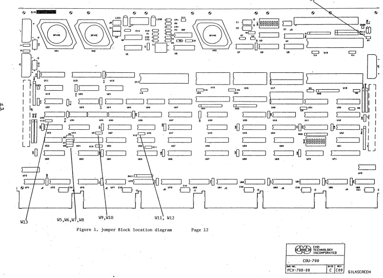
WI3 W5,W6,W ,W8 W9,WIO WII, WI2
Figure 1. jumper Block location diagram
VRlI
U7
I !
UIS UI6
c:::Jm [=::Jeri
U20 U29
I
)I
)II II
RN4 RIlS
0
. ~a U30 UlI9
liD
~ U49 U49US9 US9
aO
~UG7 U68
Page 12
IJ8
I
~
UI7
I
~
U3010
5) U10 USO ) . U60 U69 W4. . - - _ - , .... jrrj
=====:1
li~I.-~-~I~~---~
us
U7I
[=::J UII
til
071
~CMD TECHNOLOGY
INCORPORATED
CDU-700
DllCtIl.
,BIlE I REV
[image:14.792.43.790.41.583.2]SW1-1 OFF ON ON SWl-6 SWl-7 SWl-8 SWl-5 ON ON ON ON OFF OFF OFF OFF SW2 W3 W4 W4
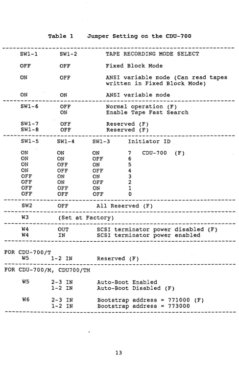
Table 1
SW1-2 OFF OFF ON OFF ON OFF OFF SWl-4 ON ON OFF OFF ON ON OFF OFF OFF
Jumper Setting on the CDU-700
TAPE RECORDING MODE SELECT
Fixed Block Mode
ANSI variable mode (Can read tapes written in Fixed Block Mode)
ANSI variable mode
Normal operation (F) Enable Tape Fast Search
Reserved (F) Reserved (F)
SWl-3 Initiator ID
ON 7 CnU-700 (F)
OFF 6
ON 5
OFF 4
ON 3
OFF 2
ON 1
OFF 0
All Reserved (F)
(Set at Factory)
OUT IN
SCSI terminator power disabled (F) SCSI terminator power enabled
FOR CDU-700/T
W5 1-2 IN Reserved (F)
---FOR CDU-700/M, CDU700/TM
W5 2-3
IN
Auto-Boot Enabled1-2 IN Auto-Boot Disabled (F)
W6 2-3
IN
Bootstrap address = 771000 (F)1-2
IN
Bootstrap address = 773000 [image:15.617.58.547.32.785.2]---CDU-700/T Tape Only with Ie P70012C at U54:
Please refer to Appendix D for the other 22 CSR jumper settings.
W6 W10 W7 W8 W9 CSR Address of PDP-II
2-3 IN 1-2 IN 1-2 IN 1-2 IN . 2-3 IN Standard CSR: 17774500 (F)
2-3 IN 1-2 IN 2-3 IN 1-2 IN 2-3 IN Second CSR: 17760404
2-3 IN 1-2 IN 1-2 IN 2-3 IN 2-3 IN Third CSR: 17760444
2-3 IN 1-2 IN 2-3 IN 2-3 IN 2-3 IN Forth eSR: 17760504
2-3 IN 1-2 IN 1-2 IN 1-2 IN 1-2 IN Fifth eSR: 17760544
2-3 IN 1-2 IN 2-3 IN 1-2 IN 1-2 IN Sixth CSR: 17760410
2-3 IN 1-2 IN 1-2 IN 2-3 IN 1-2 IN Seventh CSR: 17760450
2-3 IN 1-2 IN 2-3 IN 2-3 IN 1-2 IN Eighth CSR: 17760454
The old IC P70012B at location U54 of the CDU-700/T only supports
8 eSR addresses. The jumper settings are the same as those shown
above.
CDU-700/M Disk only with IC P70011B at U54:
W7
we
W9 eSR Address1-2 IN 1-2 IN 2-3 IN Standard CSR: 17772150 (F)
2-3 IN 1-2 IN 2-3 IN Second CSR: 17760334
1-2 IN 2-3 IN 2-3 IN Third CSR: 17760354
2-3 IN 2-3 IN 2-3 IN Forth CSR: 17760374
1-2 IN 1-2 IN 1-2 IN Fifth CSR: 17760340
2-3 IN 1-2 IN 1-2 IN Sixth CSR: 17760344
1-2 IN 2-3 IN 1-2 IN Seventh CSR: 17760350
2-3 IN 2-3 IN 1-2 IN Eighth CSR: 17760360
WI0 1-2 IN Reserved
---CDU-700/TM Tape and Disk with IC P70013A at U54:
W7
we
CSR Address1-2 IN 1-2 IN Tape Standard CSR: 17774500 (F)
2-3 IN 1-2 IN Tape Second CSR: 17760404
1-2 IN 2-3 IN Tape Third
CSR:
177604442-3 IN 2-3 IN Disable Tape
W9 WI0 CSR Address
1-2 IN 1-2 IN Disk Standard CSR: 17772150 (F)
2-3 IN 1-2 IN Disk Second CSR: 17760334
1-2 IN 2-3 IN Disk Third CSR: 17760354.
2-3 IN 2-3 IN Disable Disk
Wll W12
2-3 IN 2-3 IN
1-2 IN
W13
2-3 IN
1-2 IN
1~2 IN
1-2 IN 2-3 IN
1 word per DMA burst (F Tape)
2 words per DMA burst
4 words per DMA burst (F Disk)
4 uS dwell time between DMA (F Disk)
2 uS dwell time between DMA (F Tape)
Note: (F) means factory setting.
3.2 COU-700 Mounting Slot Selection
The CDU-700 can be installed in any priority on the standard PDP-11 Unibus SPC backplane. The CDU-700 is a DMA device and requires the Nonprocessor Grant (NPG) jumper on the SPC card slot in which the controller is being installed be removed. It is recommended that the CDU-700 be placed in front of other devices on the Unibus except when there is an Ethernet controller which should go first.
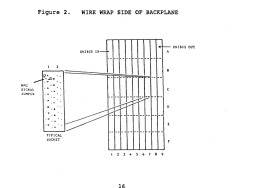
3.2.1 NPG Non-Processor Grant Signal
The NPG signal jumper is located-at pins CAl to CBl on the Unibus backplane. Figure 2 is a DDll-DK nine-slot backplane seen from the rear.
To locate the NPG jumper do the following:
From the rear of the backplane locate the card slot in which the board is to be installed. Note: Each card slot is 4 pins wide.
Locate the C socket and then locate the pins CAl and CBl. Remove the jumper wire between the two pins.
Figure 2.
WIRE WRAP SIDE OF BACKPLANE
UNIBUS l S -~
<E-~ UNIBUS OUT
A
-- ---- --1----
--1--1--1 2
B
---l============~~~kJLl~1
;~~~;-p-~~~ ~:
[ [ [ [J~[~--~~
c• • ' . I
-"""r:::v
.~ ~...-.~
o
...
,• & • • •
'I~vt:::vv
. • , . ' , . ~~I-_I-___
I-_____
_ 4' C ' • E
, c
TYPICAL
SOCKET
-- ---1--
--F1 2 ) , 5 6 7 8 9
[image:18.615.62.571.377.753.2]3.3 DMA Burst Length and Dwell Time
The Busrt Length determines how many words the COU-700 transfers by OMA during each NPR. The Dwell time is the time the COU-700 waits before i t requests for another NPR.
Wll W12
2-3 IN 2-3 IN 1 word per NPR
2-3 IN 1-2 IN 2 words per NPR
1-2 IN 1-2 IN 4 words per NPR
W13 1-2 IN 4 micro second dwell time
2-3 IN 2 micro second dwell time
Factory Settings:
COU-700/T 1 word per NPR, 2 micro second dwell time
COU-700/M, CDU-700/TM 4 words per NPR, 4 micro second dwell time
IMPORTANT: If the CDU-700 is installed in a VAX BI unibus (VAX 8350, 8750, etc) the setting must be 1 word per NPR and 2 micro second dwell time. Data compare errors will occur on the VAX BI Unibus if the throughput is set to more than the BI unibus adapter can handle. On the POP-II and Non-BI VAX (VAX-730, 750, 780, and others) Unibus the user may set the controller to 4 words per NPR and 4 micro second Dwell time.
3.4 SCSI Bus Cabling and Termination
The CDU-700 provides a 50-pin connector (J3), to interface with external SCSI devices.
When the CDU-700 and the external SCSI drives are installed in the same cabinet which meets EMI/RFI shielding requirements, a 50-conductor flat cable or 25-signal twisted-pair cable can be used for connecting the CDU-700 (J3) and the external SCSI drives When the CDU-700 and the external SCSI drives are installed in seperated cabinets, the shielded SCSI cable should be used to meet FCC requirements.
Note'that a minimum conductor size of 28AWG shall be employed to minimize noise effects and ensure proper distribution of optional terminator power. The maximum cable length is 6.0 meters or 20 feet in single ended mode.
.
The SCSI bus signals should be terminated with 220 ohms to +5 volts and 330 ohms to ground at each end of the cable. The CDU-700 provides on-board removable terminators (RN7,RN8,RN10), which are next to the connector Jl. Therefore, the CDU-700 can be installed in any position of the SCSI cable. If the CDU-700 is installed at either end of SCSI cable, the on-board SCSI bus terminators should remain on the board. Otherwise, the on-board SCSI bus terminators should be removed.
CHAPTER 4
ON-BOARD UTILITY
4.1
Disk Utility for the CDU-700/M, CDU-700/TM
The CMD Technology Utility Program provides a convenient means of
formatting and configuring the drive and configuring the logical
unit number offset.
The utility program can be started by means
of an ODT command. For Example:
PDP-l1/24 SYSTEMS
1.
Hit the Boot Switch.
2.
Halt the processor.
3. 17772152/004400 123456
<CR>
4.
17772152/001000 100<CR>
5. 5000G
iDEPOSIT
123456TO
i
CSR BASE ADDRESS
+2
iDEPOSIT 100 TO
i
CSR BASE ADDRESS
+
2
;5000
and a G
iThe Utility program
iwill begin executing.
Note that the address shown in step 3 is equal to the CSR address
selected by jumper
W7and
we
plus 2.
PDP-11/34 SYSTEMS
1.
Enter ODT mode
2.
From the terminal type
·
,
DEPOSIT
123456TO
L 772152
<CR>
·
,
CSR BASE ADDRESS
+ 2D
123456<CR>
3. L 772152
<CR>
,
·
DEPOSIT
100TO
D 100
<CR>
,
·
CSR BASE ADDRESS
+ 24. L 5000
<CR>
,
·
5000and a S
S
<CR>
·
,
The Utility program
·
will begin executing.
,
For the CDU-700/M, the utility will display:
CMD TECHNOLOGY UTILITY PROGRAM
COPYRIGHT 1987, CMD TECHNOLOGY, INC.
SELECT CSR ADDRESS
1
=
7721502
=
7603343
=
7603544
=
7603745
=
7603406 = 760344
7 = 760350
8 = 760360
WHICH CSR #
;The user will then
;select the number which ;matches with the CSR ;address selected by ;jumpers W7, W8, W9
For the CDU-700/TM, the utility will display:
CMD TECHNOLOGY UTILITY PROGRAM
COPYRIGHT 1987, CMD TECHNOLOGY, INC.
4.1.1
SELECT CSR ADDRESS
1 = 772150
2
=
7603343 = 760354
4 = 774500 (TAPE)
5
=
760404 (TAPE)6 = 760444 (TAPE)
WHICH CSR #
Configure LON Offset
iThe user will then
iselect the number which jmatches with the CSR iaddress selected by ijumpers W7,W8,W9,W10
LUN Offset: For LSI-11 systems, each MSCP drive requires
a
different Logical Unit Number. If there are no other MSCP
controllers in the system, then the LUN offset number
is
0(Drive 0 will be LUN 0, and Drive 1 will be LUN 1). If there
exists another MSCP controller with 4 LUN units
(0'
to 3), thenthe LUN offset should be 4. In this case Drive 0 will be LUN 4
and Drive 1 will be LUN 5. Normally, when the CDU-700
is
used inVMS operating system, the LUN Offset should remain as factory
setting (LUN=O).
The operator now has 6 options to choose from. To specify or to
check the configuration of a drive, the operator types in a 2.
If at any time the operator types in a ctrl C, the command is
aborted and the utility program returns to the main menu. If the
operator types in <CR> with no value, then the parameters will
remain unchange.
In order to store any changes permanently, the user must give the
correct password. The password is CMD.
MAIN MENU
1
=
BOOT DRIVE2
=
CONFIGURE LUN OFFSET3
=
FORMAT DRIVE4
=
QUALIFY DRIVE5
=
MANUAL REPLACE BAD SECTORS6
=
READ, WRITE AND VERIFY TESTSELECT OPTION: 2
PRESENT LUN OFFSET = 0, ENTER NEW VALUE:
SAVE NEW CONFIGURATION (Y or N)? Y
ENTER PASSWORD: CMD
COMPLETE.
4.1.2 Format Drive
Formatting a drive will rewrite all the sectors on the drive. In
this option, the CDU-700 issues Format Unit Command to the
selected SCSI disk drive and requests i t to map out the defects
on the Manufacture Defect List (MDL). It is recommended to use
qualify drive option after formatting the drive. In order to
format or qualify the drive, the correct password is needed. The
password is CMD.
1 = BOOT DRIVE
2
=
CONFIGURE LUN OFFSET3
=
FORMAT DRIVE4
=
QUALIFY DRIVE5 = MANUAL REPLACE BAD SECTORS
6 = READ, WRITE AND VERIFY TEST
SELECT OPTION: 3
ENTER DRIVE NUMBER <0 TO 6>: 0
***
WILL DESTROY DATA ON DRIVE 0, ARE YOU SURE? YENTER PASSWORD: CMD
WAIT ..•..
4.1.3
Qualify Drive
The qualify program will write different patterns into the drive
and then verify the pattern. If there is any bad sector, the
sector will be automatically replaced.
To ensure a defect free drive, the qualify program should be run
at least 10 passes.
1
=
BOOT DRIVE2
=
CONFIGURE LUN OFFSET3
=
FORMAT DRIVE4
=
QUALIFY DRIVE5
=
MANUAL REPLACE BAD SECTORS6
=
READ, WRITE AND VERIFY TESTSELECT OPTION: 4
ENTER PASSWORD: CMD
QUALIFY DRIVE # <0 TO 6>: 0
***
WILL DESTROY DATA ON THIS DRIVE, ARE YOU SURE?QUALIFY LOOP 1
TO ABORT, ENTER ~C ( CONTROL C).
4.1.4
Manual Replace Bad Sectors
This program allows user to replace bad sectors found in the
future.
1 = BOOT DRIVE
2 = CONFIGURE LUN OFFSET
3
=
FORMAT DRIVE4 = QUALIFY DRIVE
5 = MANUAL REPLACE BAD SECTORS
6
=
READ, WRITE AND VERIFY TESTSELECT OPTION: 5
ENTER PASSWORD: CMD
ENTER DRIVE NUMBER <0 TO 6>: 0
REPLACE LOGICAL BLOCK NUMBER? XXXXXX
REPLACE LOGICAL BLOCK XXXXXX. ARE YOU SURE? Y
4.1.5 Read, Write and Verify Test
This option allows user to test the integrity of the controller
board, drive cable and disk drive. The program will generate
random data patterns for testing.
1
=
BOOT DRIVE2
=
CONFIGURE LUN OFFSET3
=
FORMAT DRIVE4
=
QUALIFY DRIVE5
=
MANUAL REPLACE BAD SECTORS6
=
READ I WRITE AND VERIFY TESTSELECT OPTION: 6
RANDOM READ WRITE TEST
DO YOU WANT READ ONLY ? <Y OR N>
ENTER PASSWORD: CMD
DRIVE NUMBER <0 TO 6>: 0
***
WILL DESTROY DATA ON THIS DRIVE, ARE YOU SURE?TEST FROM BLOCK # <O-XXXXX> ?
TO BLOCK # <XXXXX-YYYYY> ?
TESTING STARTED. TYPE CTRL-C TO ABORT.
4.1.6 Utility Bootstrap
To bootstrap the operating system on drive 0 to 6, just select
option 1 from MAIN MENU.
1
=
BOOT DRIVE2
=
CONFIGURE LUN OFFSET3
=
FORMAT DRIVE4
=
QUALIFY DRIVE5
=
MANUAL REPLACE BAD SECTORS6
=
READ, WRITE AND VERIFY TESTSELECT OPTION: 1
BOOT DRIVE NUMBER <0 TO 6> 0
BOOT DUO. ARE YOU SURE? Y
4.2
Tape Utility for the
CDU-700fT, CDU-700fTMThe utility program can be started by means of an ODT command.
For Example:
PDP-ll/24 SYSTEMS
1. Hit the Boot Switch.
2. Halt the processor.
3. 17774502/004700 123456 <CR>
4. 17774502/001000 100 <CR>
5. 5000G
iDEPOSIT 123456 TO
i CSR BASE ADDRESS + 2 iDEPOSIT 100 TO
i CSR BASE ADDRESS + 2
;5000 and a G
iThe Utility program ;will begin executing.
Note that the address shown in step 3 is equal to the CSR address
selected by jumper W7,
wa,
and W9 plus 2.PDP-l1/34 SYSTEMS
1. Enter DDT mode
2. From the terminal type
·
,
DEPOSIT 123456 TOL 774502 <CR> ; CSR BASE ADDRESS + 2
D 123456 <CR>
3. L 774502 <CR> ; DEPOSIT 100 TO
D 100 <CR>
,
·
CSR BASE ADDRESS + 24. L 5000 <CR> ; 5000 and a S
S <CR> ; The Utility program
·
will begin executing.,
For the CDU-700/T, the utility will display:
CMD TECHNOLOGY UTILITY PROGRAM
COPYRIGHT 1987, CMD TECHNOLOGY, INC.
SELECT CSR ADDRESS
1
=
7745002 = 760404
3
=
7604444
=
7605045
=
7605446
=
7604107
=
7604508 = 760454
WHICH CSR #
iThe user will then
iselect the number which ;matches with the CSR ;address selected by
ijumpe~s W7
we
For the CDU-700/TM, the utility will display:
CMD TECHNOLOGY UTILITY PROGRAM
COPYRIGHT 1987, CMD TECHNOLOGY, INC.
4.2.1
SELECT CSR ADDRESS
1 = 772150
2
=
7603343
=
7603544 = 774500 (TAPE)
5
=
760404 (TAPE)6
=
760444 (TAPE)WHICH CSR #
Configure Tape LUN Offset
;The user will then
;select the number which ;matches with the CSR iaddress selected by ijumpers W7,W8,W9,WI0
LUN Offset: For PDP-II only, TMSCP requires that each TMSCP
drive has a different Logical Unit Number. If there are no other
TMSCP controllers in your system, then the LUN offset number is 0
(Drive 0 will be LUN 0, and Drive 1 will be LUN 1). If there
exists another TMSCP controller with 4 LUN units (0 to 3), then
the LUN offset should be 4. In this case Tape Drive 0 will be LUN 4 and Tape Drive 1 will be LUN 5.
The operator now has 1 option to choose from. To configure the
LUN offset, the operator types in a 1. If at anytime the
operator types in a ctrl C, the command is aborted and the
utility program returns to the main menu. If the operator types
in <CR> with no value, then the parameters will remain unchange.
In order to store any changes permanently, the user must give the
MAIN MENU
1 = CONFIGURE LUN OFFSET
SELECT OPTION: 1
PRESENT LUN OFFSET
=
0, ENTER NEW VALUE:SAVE NEW CONFIGURATION (Y or N)? Y
ENTER PASSWORD: CMD
COMPLETE.
4.3 ODT Utility
When the CDU-700/M is used in VAX-11/730, 750, 780 systems, the
ODT utility
is
required to format or qualify a disk drive.The addresses of IP and SA registers of CDU-700/M for VAX-11/730
and VAX-11/750 are listed in the following table.
OCTAL ADDRESS
772150 772152
760334 760336
760354 760356
760374 760376
760340 760342
760344 760346
760350 760352
760360 760362
HEX ADDRESS
FFF468 FFF46A
FFEODC FFEODE
FFEOEC FFEOEE
FFEOFC FFEOFE
FFEOEO FFEOE2
FFEOE4 FFEOE6
FFEOE8 FFEOEA
FFEOFO FFEOF2
The addresses of IP and SA registers of CDU-700/M for VAX-11/780 are listed in the following table.
OCTAL ADDRESS 772150 772152 760334 760336 760354 760356 760374 760376 760340 760342 760340 760342 760350 760352 760350 760352 HEX ADDRESS FOR UBA 1
2013F468 2013F46A 2013EODC 2013EODE 2013EOEC 2013EOEE 2013EOFC 2013EOFE 2013EOEO 2013EOE2 2013EOE4 2013EOE6 2013EOE8 2013EOEA 2013EOFO 2013EOF2 HEX ADDRESS FOR UBA 2
2017F468 2017F46A 2017EODC 2017EODE 2017EOEC 2017EOEE 2017EOFC 2017EOFE 2017EOEO 2017EOE2 2017EOE4 2017EOE6 2017EOE8 2017EOEA 2017EOFO 2017EOF2 HEX ADDRESS FOR UBA 3
201BF468 201BF46A 201BEODC 201BEODE 201BEOEC 201BEOEE 201BEOFC 201BEOFE 201BEOEO 201BEOE2 201BEOE4 201BEOE6 201BEOE8 201BEOEA 201BEOFO 201BEOF2 HEX ADDRESS FOR UBA 4
201FF468 201FF46A 201FEODC 201FEODE 201FEOEC 201FEOEE 201FEOFC 201FEOFE 201FEOEO 201FEOE2 201FEOE4 201FEOE6 201FEOE8 201FEOEA 201FEOFO 201FEOF2
On a VAX-ll/730 or VAX-11/750, please follow the example to
specify LUN offset, verify LUN offset, format a drive, or qualify
a drive.
In
this example, first CSR address is assumed.4.3.1 Specify LUN Offset
»>
D/W/P FFF468 0»>
D/W/P FFF46A A72E»>
D
*
22»>
D*
04.3.2 Verify LUN Offset
»>
D/W/P FFF468 0»>
D/W/P FFF46A A72E»>
D
*
23»>
E*
jWRITE IP ANY VALUE
jWRITE SA, ADDRESS=CSR+2 iWRITE SA WITH COMMAND jWRITE LUN OFFSET VALUE
iWRITE IP ANY VALUE
iWRITE SA, ADDRESS=CSR+2 iWRITE SA WITH COMMAND
4.3.3 Format a Drive
»>
D/W/P FFF468»>
D/W/P FFF46A»>
D*
20»>
D*
0»>
D*
0»>
E*
o
A72E
4.3.4 Qualify a Drive
»>
D/W/P»>
D/W/P»>
D
*
21»>
D*
0»>
E
*
FFF468
FFF~6A
o
A72E
iWRITE IP ANY VALUE
iWRITE SA, ADDRESS=CSR+2 iWRITE SA WITH COMMAND iSELECT DRIVE 0
iDRIVE SERIAL NUMBER iVALUE=20000, FORMATTING iVALUE=O,FORMAT COMPLETE
iWRITE IP ANY VALUE
iWRITE SA, ADDRESS=CSR+2 iWRITE SA ,WITH COMMAND
iSELECT DRIVE 0
iSHOW CURRENT QUALIFY
iLOOP COUNT
On a VAX-II/780, please follow the example to specify LUN offset,
verify LUN offset, format a drive, or qualify a drive. In this
example, first CSR address of UBA 1 is assumed.
4.3.5 Specify LUN Offset
»>
D/W/P 2013F468»>
D/W/P 2013F46A»>
D*
22»>
D*
0o
A72E
4.3.6 Verify LUN Offset
»>
DjW/P 2013F468»>
D/W/P 2013F46A»>
D*
23»>
E*
o
A72E
28
iWRITE IP ANY VALUE
iWRITE SA, ADDRESS=CSR+2 iWRITE SA WITH COMMAND iWRITE LUN OFFSET VALUE
iWRITE IP ANY VALUE
4.3.7 Format a Drive
»>
D/W/P 2013F468»>
D/W/P 2013F46A»>
D*
20»>
D*
0»>
D*
0»>
E
*
4.3.8 Qualify a Drive
»>
D/W/P 2013F468»>
D/W/P 2013F46A»>
D * 21»>
D*
0»>
E*
o
A72E
o
A72E
jWRITE IP ANY VALUE
jWRITE SA, ADDRESS=CSR+2 jWRITE SA WITH COMMAND jSELECT DRIVE 0
jDRIVE SERIAL NUMBER jVALUE=20000, FORMATTING jVALUE=O,FORMAT COMPLETE
jWRITE IP ANY VALUE
jWRITE SA, ADDRESS=CSR+2 jWRITE SA WITH COMMAND jSELECT DRIVE 0
jSHOW CURRENT QUALIFY
CHAPTER 5 SOSI INFORMATION
5.1 SCSI DEFINITIONS:
Connect: The function that occurs when an initiator selects a target to start an operation.
Disconnect: The function that occurs when a target release control of the SCSI bus, allowing i t to go to the BUS FREE phase.
Initiator: An SCSI device (usually a host system) that requests an operation to be performed by another SCSI device.
4
LUN: Logic Unit Number
Peripheral device: A peripheral that can be attatched to an SCSI device (e.g., magnetic disk, magnetic tape, or optical disk).
Reconnect: The function that occurs when a target selects an initiator to continue an operation after a disconnect.
SCSI address: The octal representation of the uniqu~ address (0-7) assigned to an SCSI device. This address would normally be assigned and set in the SCSI device during system installation.
SCSI ID: The bit-significant representation of the SCSI address refering to one of the signal lines DB(7~0).
SCSI device: A host computer adapter or a peripheral controller or an intelligent peripheral that can be attatched to the SCSI bus.
Target: An SCSI device that performs an operation requested by an initiator.
5.2
SCSI Commands
SCSI
commands used by CDU-700 for MSCP emulation are listed
inthe following table.
Code
OOh
01h
03h
04h
07h
OBh
OAh
OBh
l2h
lSh
lAh2Sh
28h 2Ah2Bh
3Eh 3FhCommand Name
Test Unit Ready
Rezero Unit
Request Sense
Format unit
(1)Reassign-Block
Read
Write
Seek
Inquiry
Mode Select
Mode Sense
Read Capacity
Extended Read (2)
Extended Write(2)
Extended Seek (2)
Read Long
(3)Write Long(3)
(1)
The Format Unit command is used by the on-board utility only.
(2)
These commands are used only when the disk drive capacity is
greater than
1Giga bytes.
(3)
These commands are used if the drives support them.
SCSI
commands used by CDU-700
for TMSCP emulation are listed as
follows:
Code
OOh
01b
03b
08hOAh
lOh
llb 12hlSh
19h
lAh
1Bh
Command Name
Test unit Ready
Rewind
Request Sense
Read
write
Write Filemark
Space
Inquiry
Mode Select
Erase
5.3 SCSI Status
The SCSI status codes used by CDU-700 are listed as follows:
5.4
Code
OOh
02h
OSh
SCSI Messages
Status Name
Good
Check Condition Busy
The SCSI Messages used by CDU-700 are listed as follows:
Code
OOh
Olb
02h 03h 04h
OSh
07h
OSh
09b 80-FFb
Message Name
Command Complete Extended Message Save Data Pointer Restore Pointer Disconnect
Initiator Detected Error Message Reject
No Operation
Message Parity Error Identify
5.5
SCSI Single-Ended Signals
Pin assignment of the CDU-700 SCSI Cable Connector (J1,J2,J3):
Signal Pin Number
-DB(O) 2
-DB(1) 4
-DB(2) 6
-DB(3) 8
-DB(4) 10
-DB(S) 12
-DB(6) 14
-DB(7) 16
-DB(P) 18
GROUND 20
GROUND 22
GROUND 24
TERMPWR 26
GROUND 28
GROUND 30
-ATN 32
GROUND 34
-BSY 36
-ACK 38
-RST 40
-MSG 42
-SEL 44
-C/D 46
-REQ 48
-I/O 50
NOTE: All odd pins except pin 25 are connected to ground. Pin 2S
is left open. The minus sign next to the signal indicates active
Warranty
Return and
BASIC WARRAN1Y -In the absence of any optional warranty or continuing provisions by formal agree-ment, CMD warrants its products in accordance with the schedules listed below. Purchaser hereafter men-tioned refers at all times to the c~stome~ who purchased CMD product(s). .
HOST ADAPTER WARRANTY - CMD warrants Host Adapter products of its manufacture to be free from defect in material and workmanship for a period of one year from the date of shipment. During this pe-riod, if the customer experiences difficulties with a CMD Host Adapter and is unable to resolve the prob-lem via phone with CMD Technical Support, a Return Material Authorization (RMA) will be issued. Fol-lowing receipt of an RMA, the Purchaser is responsible for returning the product to CMD, freight prepaid. CMD, upon verification of warranty, will repair or replace at its option the Host Adapter in question, and will then return the product to the Purchaser, freight prepaid.
CABLE WARRAN1Y - All CMD provided cables are warranted for ninety (90) days from the time of ship-ment. Questionable cables should be returned to CMD, freight prepaid, where they will be repaired or re-placed by CMD at its option and returned to the Purchaser, freight prepaid.
GENERAL TERMS - The above warranties shall not apply to expendable components such as fuses, bulbs, and the like, nor to connectors, adapters, and other items not a part of the basic product. CMD shall have no obligation to make repairs or to cause replacement required through normal wear and tear or necessi-tated in whole or in part by catastrophe, fault or negligence of the user, improper or unauthorized use of the product, or use of the product in such a manner for which it was not desigTled, or by causes external to the product, such as, but not limited to, power failure or air conditioning. CMD's sole obligation hereun-der shall be to repair or replace any defective product, and, unless stated, ray return transportation costs within the United States of America for such replacement. Purchaser shal provide labor for removal of the defective product, shipping charges for return to CMD and installation of its replacement. On-site ser-vices are not a part of this warranty. Above warranties are subject to change without notice.
RETURNED MATERIAL - Warranty claims must be received by CMD within the applicable warranty pe-riod. A replaced product, or part thereof, shall become the property of CMD and shall be returned to CMD at Purchaser's expense. All returned material must be accompanied by a Return Materials Authoriza-tion (RMA) number assigned by CMD. For RMA numbers, call CMD at (714) 454-0800.
THE EXPRESSED WARRANTIES SET FORTH IN THIS AGREEMENT ARE IN LITU OF ALL OTHER WARRANTIES, EXPRESSED OR Itv1PLIED, INCLUDING WITHOUT LIMIT A TION, ANY Vv' ARRANTIES OF MERCHANTABILITY OR FITNESS FOR A PARTICULAR PURPOSE, AND ALL SUCH OTHER RANTIES ARE HEREBY DISCLAIMED AND EXCLUDED BY CMD. THESE STANDARD EXPRESS WAR-RANTIES ARE IN LIEU OF ALL OBLIGATIONS OR LIABILITIES ON THE PART OF CMD FOR DAM-AGES, INCLUDING BUT NOT LIMITED TO SPECIAL, INDIRECT OR CONSEQUENTIAL DA!\1AGES ARISING OUT OF OR IN CONNECTION WITH THE USE OR PERFORMANCE OF THE PRODUCT.
Repair Policy \VARRANTY PERIOD
The following warranty period is from the date of shipment:
CMD Host Adapter one year
Cable 90 days
Drive manufacturer's warranty
RETURN FOR CREDIT
The allowable period of return for credit from the date of shipment is as follows
CMD Host Adapter less than 90 days
Cable less than 60 days
Drive not applicable
RETURN FOR REPAIR CMD Host Adapter
In-Warranty (Less then 1 year)
• CMD offers a 15 working day turnaround repair service at the cost O'f'par-ts only. Defective boards will be repaired and returned to the customer within 15 working days from the date of return to CMD. • CMD also offers two In-Warranty 24 hour erpediting services:
24 Hour Turnaround Loaner Service:
Under this policy, CMD will ship a loaner in 24 hours during regular working days to the customer for a charge of S100.00 per loaner. Upon receiving the loaner, customer must return the defective board to CMD within seven (7) days for repair. CMD will repair the defective board and return the board to the customer. Customer must then return the loaner in seven. (7) days after the receipt of the repaired board. Approval for loaner service is based on credit verification.
24 Hour Turnaround Swap Service: .
In the case thatthe defective board is within the first six (6) months of the warranty, CMD, at its own option, offers a 24 hour turnaround swap service. CMD will ship the same model of the board to customer within 24 hours during working days in exchange for the defective board. CMD will swap with a new board if board is not functional upon arrival. For all other cases, swap will occur with either a new or refurbished b<;>ard for a charge of $200.00. CMD does not offer swap services for boards that are purchased more than six months from the date of shipment. Customer is
sible for returning the defective board to CMD within seven (7) days after receipt of the swapped board.
• The remaining warranty period shall apply to the repaired or swapped board. Out-of-Warranty (more than 1 year)
• CMD offers a 15 working day turnaround repair service at a rate of 5300.00 plus parts and freight for all
out-of-warranty host adapter boards. Defective boards will be repaired and returned to customer within 15 working days starting with date of return to CMD.
• CMD also offers an out-of-warranty 24 Hour Turnaround Loaner Service:
Under this policy, CMD will ship the same model loaner in the 24 hour time frame of working days to customer for an additional charge of S100.00 plus freight per loaner. The loaner is for use by the customer during the period that the defective board is being repaired. Customer is responsible for re-turning the defective board to CMD within seven days after the receipt of loaner and rere-turning the loaner in seven (7) days once the defective board is repaired and received. The approval of the loaner service is at CMD's option and based upon customer credit verification.
• CMD will extend warranty for a period of six (6) months on any out of- warranty repaired board. Cable
In-,\",Tarranty (90 days) - free swap.
Out-of-Warranty (90 days) - not applicable. Drive
In-Warranty (per manufacturer) - manufacturer charge only.
Out-of-Warranty (per manufacturer) - manufacturer charge plus S100 CMD handling.
RETURN FOR UPGRADE/UPDATE CMD Host Adapter
In-Warranty (less than 1 year)
• CMD offers a 15 working day turnaround different function upgrade service for boards that can be
up-graded to a higher function; and a free 15 worbng day turnaround ECO Field Upgrade for all its boards.
C:t-..1D will upgrade the hardware of its board to a higher function for a charge of the difference of list
prices of the original and upgraded functions. CMD v·:ill also update its board to its latest firmware release at no charge to the customer. Boards will be upgraded/updated and returned to the cus-tomer within 15 working days from the date of return to CMD.
• Ct\1D also offers 24 hour turnaround loaner service as stated in "RETURN FOR REPAIR."
• ·The remaining warranty period shall apply to the updated board. For upgraded boards, CMD will extend warranty for a period of six months.
Out-of-Warranty (More than 1 year)
• CMD offers a 15 working day turnaround different fu11dion upgrade service for boards that can be
up-graded to a higher function at a charge of the difference of list prices of two functions. CMD also of-fers a free 15 working day turnaround ECO Field Upgrade for all its boards. Boards will be
up-graded/updated and returned to customer within 15 \,\Torking days from the date of return to CMD. • CMD also offers 24 hours turnaround Loaner Service as stated in "RETURN FOR REPAIR."
• There will be no warranty extension for same function firmware update. For different function Hardware upgrade, CMD ,vill extend warranty for a period of six (6) months.
Drive-same as in "RETURN FOR REP AIR."
SHIPPING CHARGES
The following shipping charges apply to all REP AIR, SWAP, LOANER, and UPGRADE UNITS. In-Warranty
• Domestic - freight from CMD to customer is to be paid by CMD; freight from customer to CMD is to be paid by customer.
• International- all fees are to be paid by customer (including custom duty and broker fees). Out-of Warranty
.• Domestic - all fees are to be paid by customer.
• International- all fees are to be paid by customer (including custom duty and broker fees).
GENERAL CONDITIONS
All goods returned to CMD including returns for credit, sv.'ap return.s, loaner returns, and evaluation re-turns shall remain in good condition. Any damage or alteration done by the customer will result in a rejec-tion or addirejec-tional charge to the customer.
Appendix B
Operating Systems Supported by CDU-700
All DEC-compatible products designed by CMD Technology, Inc.
implement MSCP (Mass Storage Control Protocol)/ TMSCP (Tape Mass
Storage Control Protocol). CMD supports its implementation of
MSCP/TMSCP beginning with the indicated version of the following
DEC operating systems. ~
Operating System
VMS Ultrix
UNIX/Berkeley RSX-IIM
RSX-11M-PLUS RSTS/E
RT-1l DSM-11
ISM-11 TSX VAXELN
35
Version
4.0 and 5.0 1.2
4.2 4.1 3.0 9.0 5.2 3.3 3.4
Appendix C
SCSI Devices Supported
byCDU-700
Disk drives supported
byCDU-700/M,CDU-700/TM SCSI host adapter:
10/18/1989
***
indicates new qualified device.Magnetic disk drives:
CDC WREN-III, WREN-IV, WREN V, WREN VI
SWIFT (3 1/2"), Sabre (8")
***
CITOH YD-3042, YD-3082
CONNER PERIPHERALS CP-340, CP-31UO
FUJITSU M2246SA, M2249SA Series
HITACHI DK515C Series
HP
IBM
MAXTOR
MICROPOLIS
PRIAM
QUANTUM
RODIME
SIEMENS
SYQUEST
TOSHIBA
EMULEX
97548S/D series
***
320MB, 3 1/2"
***
XT-3000 ,XT-4000S, XT-8000S Series
1370 Series
Model 717, 728, 738
ProDrive 40S/80S
3085S, 5215S, 5180S
Model 2200, 2300
SQ555
***
MK156FB series
MD21, MD23 (SCSI TO ESDI CONTROLLER)
Erasable Optical disk drives:
SONY
RICOH
CD ROM drives:
LMS
TOSHIBA
SMO-D501
RO-5030E
CM210, CM212
***
XM3200 series
***
Magneto Optical disk
WORM drives:
1. with Ten
X
Technology Optical Convertion UnitMAX TOR
LMSI
MITSUBISHI
PIONEER
RXT-SOOS, ReV.J K
LD510, LD1200
MW-5U1
DD-55001 etc.
2. with LASERDRlVE interface
LASERDRIVE Model 800 series
***
Tape drives supported by CDU-700/T,CDU-700/TM SCSI host adapter:
10/18/1989
EXABYTE
GIGATREND
SONY
HP
ARCHIVE
ASPEN
CALIPER
CIPHER
FUJITSU
KENNEDY
LMS
TANDBERG
TEAC
WANGTEK
***
indicates new qualified device.EXB-S200 8mm helical scan
1200 Series DAT, 4mm helical scan
SDT-1000 DAT, 4 rom helical scan
35450A DAT, 4 mm helical scan
***
1/4 "
1/2 ••
1/4 ..
1/4 ..
1/2 II
1/4 ..
1/2 II
1/2"
1/4 ..
1/4 II
1/4 ..
streaming
System 480, 3480 compatible
C150SAE streaming, series
ST150S-I streaming, series
M2452E, 1/2" Cartridge
streaming
9 track, model 9612
Independence, 3480 compatible
TDC3600 series
streaming
streaming
37
Appendix D 30 CSR Addresses Supported by IC P70012C
1.
e
CSR addresses supported by old IC P70012B at location U54Address PDP-II W6 WI0 W9 W8 W7
---
---
---Standard: 17774500 2-3 IN 1-2 IN 2-3 IN 1-2 IN 1-2 IN
Second: 17760404 2-3 IN 1-2 IN 2-3 IN 1-2 IN 2-3 IN
Third: 17760444 2-3 IN 1-2 IN 2-3 IN 2-3 IN 1-2 IN
Fourth: 17760504 2-3 IN 1-2 IN 2-3 IN 2-3 IN 2-3 IN
Fifth: 17760544 2-3 IN 1-2 IN 1-2 IN 1-2 IN 1-2 IN
Sixth: 17760410 2-3 IN 1-2 IN 1-2 IN 1-2 IN 2-3 IN
Seventh: 17760450 2-3 IN 1-2 IN 1-2 IN 2-3 IN 1-2 IN
Eighth: 17760454 2-3 IN 1-2 IN 1-2 IN 2-3 IN 2..,3 IN
2. 30 CSR addresses supported by new IC P70012C at location U54
Address PDP-II W6 WI0 W9 W8 W7
---
---
---1 17774500 2-3 IN 1-2 IN 2-3 IN 1-2 IN 1-2 IN
2 17760404 2-3 IN 1-2 IN 2-3 IN 1-2 IN 2-3 IN
3 17760444 2-3 IN 1-2 IN 2-3 IN 2-3 IN 1-2 IN
4 17760504 2-3 IN 1-2 IN 2-3 IN 2-3 IN 2-3 IN
5 17760544 2-3 IN 1-2 IN 1-2 IN 1-2 IN 1-2 IN
6 17760410 2-3 IN 1-2 IN 1-2 IN 1-2 IN 2-3 IN
7 17760450 2-3 IN 1-2 IN 1-2 IN 2-3 IN 1-2 IN
8 17760454 2-3 IN 1-2 IN 1-2 IN 2-3 IN 2-3 IN
---
---
---9 17760414 2-3 IN 2-3 IN 2-3 IN 1-2 IN 1-2 IN
10 17760420 2-3 IN 2-3 IN 2-3 IN 1-2 IN 2-3 .IN
11 17760460 2-3 IN 2-3 IN 2-3 IN 2-3 IN 1-2 IN
12 17760510 2-3 IN 2-3 IN 2-3 IN 2-3 IN 2-3 IN
13 17760514 2-3 IN 2-3 IN 1-2 IN 1-2 IN 1-2 IN
14 17760520 2-3 IN 2-3 IN 1-2 IN 1-2 IN 2-3 IN
15 17760550 2-3 IN 2-3 IN 1-2 IN 2-3 IN 1-2 IN
16 17760554 2-3 IN 2-3 IN 1-2 IN 2-3 IN 2-3 IN
---
---
---17 17760560 1-2 IN 1-2 IN 2-3 IN 1-2 IN 1-2 IN
18 17760604 1-2 IN 1-2 IN 2-3 IN 1-2 IN 2-3 IN
19 17760610 1-2 IN 1-2 IN 2-3 IN 2-3 IN 1-2 IN
20 17760614 1-2 IN 1-2 IN 2-3 IN 2-3 IN 2-3 IN
21 17760620 1-2 IN 1-2 IN 1-2 IN 1-2 IN 1-2 IN
22 17760644 1-2 IN 1-2 IN 1-2 IN 1-2 IN 2-3 IN
23 17760650 1-2 IN 1-2 IN 1-2 IN 2-3 IN 1-2 IN
24 17760654 1-2 IN 1-2 IN 1-2 IN 2-3 IN 2-3 IN
- - - -
---
---25 17760660 1-2 IN 2-3 IN 2-3 IN 1-2 IN· 1-2 IN
26 17760704 1-2 IN 2-3 IN 2-3 IN 1-2 IN 2-3 IN
27 17760710 1-2 IN 2-3 IN 2-3 IN 2-3 IN 1-2 IN
28 17760714 1-2 IN 2-3 IN 2-3 IN 2-3 IN 2-3 IN
29 17760744 1-2 IN 2-3 IN 1-2 IN 1-2 IN 1-2 IN