DATA PRODUCTS CORPORATION DISCfILE DIVISION
P. O. BOX 871 CULVER CITY, CALIFORNIA
December 11, 1964
Date:
"04.
(2b'f
CONTENTS
Paragraph
1.0 2.0 3.0
General
Physical Description Functional Description 3.1 Address Formnt
3.2 Sectors and Sector Organization 3.3 Control Tracks
3.4 Storage Capacity
3.5 Transfer Rates and Timing 3.~ Access Times
3.7 Control Signals and Operation Sequence 3.8 Error Signals
3.9 Equipment Life 3.10 Errors Warranty
Sheet 2 of 33
3 4 9
3.11 Design Objectives and Acceptance Error Rates
9 12 13 14 15 16 17 26 28 29 29 31 31 33 33 33 33
4.0
Interface Characteristics4.1 Controller to Logic Unit Interface 5.0 Maintenance
1.0 GENERAL
This document is the technical specification for a Mass Random Access DISCfILE Memory System. The DISCfILE System comprises two types of components referred to as the Disc Unit and the Logic Unit. The system is composed of one Logic Unit and from one to four Disc Units. Data is stored in the Disc Unit and the· Logic Unit controls the flow of data between the, Disc Unit and a system controller which interfaces and is part of a computer.
The Disc Unit contains 18 magnetically-coated discs which rotate on a common shaft. Sixteen discs are used to store data while the other two discs located at the top and bottom of the stack are used as baffle discs. The top baffle disc is also used to store timing information. The file contains the read/write heads, positioners to locate the read/write heads, selection matrices, positioner power controls, and the necessary d-c power supplies.
Air pressure is used to maintain the heads a specified dis-tance from the rotating disc surface. An entrance for exter-nally supplied compressed air, and a compressor with all required filtration is included. Either air supply may be used. All power sequencing circuitry necessary to auto-matically place the file in an operable condition or shut
it down is contained in the cabinet. Sequencing may be initiated locally at the Disc Unit or Logic Unit in test mode or remotely from the Controller.
Within the file there is a key-locked box containing 16 switches, one for each of the data discs. When anyone or more of the switches are activated, data on the corresponding discs cannot be altered or erased.
The Logic Unit is designed to execute the commands generated by the Controller. The Logic Unit uses the commands to locate a record in a DISCfILE and transfer data between the addressed record and the Controller. The Logic Unit uses an address from the Controller to select a DISCfILE and instruct the file to move a positioner to the desired
position and select a read/write head. The Logic Unit then re'ads headers (a header is an address prerecorded before each record) '~rom the DYSC:£ILE 1=9 determine if the head has settled over the desired track. This process is called track con-firmation. Then the Logic Unit controls the tra,nsfer of data between the Controller arid the record or records in the
Sheet 4 of 33
Before d'ata can be transferred between the Controller and the selected DISCfILE, the Controller must receive a signal from the Logic Unit indicating that it is ready to transfer data (at this time the Logic Unit issues the Ready signal). The Controller then responds with signals indicating whether the record,is to be read or written (this is done by the Con-troller issuing the Alert signal followed by Read or Write). After these signals are received the record is read or written. A specific time period is provided following the record during which the Controller must either terminate communication
(by issuing the End signal) or request that the next record be read or written. The Controller may terminate communica-tion any time a!ter data transfer has begun (if this is done before the end of a record when data is being written, the Logic Unit will record data
ZERO's
in the remainder of the record).The Logic Unit will also write headers either on co~mand
from the Controller or by internal programming on the
maintenance panel (the circuit modules necessary to perform this function are not included in the Logic Unit).
2.0 PHYSICAL DESCRIPTION
2.1 General
The Logic Unit is hinged to the Disc Unit. Both units are"total'lY enclosed with a minimum of trim; access is gained through simple sheet metal doors. Cable e~try is through the base of the units. All exterior metal surfaces are coated either with zinc chromate primer or paint specified by Data Products. The structural frames of both units are anodized aluminum.
2 .. 2 Physical Characteristics
2.2.1
2.2.2.
Environmental Specifications
Operating
Temperature: 600F min. o
to 85 F max.
Relative Humidity: 20% min. to 80% max.
Dimensions
Shipping and Storage
Temperature: 200F min. to l500F max. Relative Humidity: 98% max.
KOTE:
/
/:;
I I
I ' I
I ' I ~--... ~- __
L
:;!:',
I I I !/
~
.--H-
::==
=:::LII
\
I \". /1 1 I .\
I
/ I i I ;, ~ \
I
/1 I i II " \i---H
ii
.~I
f r - - - _ _ _ ---l;'---,~ - - - -L ;: i - ----~
I
\.
::
.,',
-,\
\
II
i!I
1;i
\
l
' l ! - ; = : : : - ; - r , , - " , - ,
I;
jffiJlCjiJ r:=;=:=-, I, ;I
~: ~l-!~ ~ iii LU .. , !. .112 APPROX \:"
-:.;!
I'll l § J ' ,I ;,~,:,~;I
I :':':"::;\ 1112.~~
1,-;·':I
"'-..
Iii:":::
\:1 v."I~~~;.
I ~'L-- 1:1
. - - ..
-.J
I
,'"
'!,'>-;-/:'-)-\_-1
'-:::=:
::--1
~
II
/ \\
/
iIU
' : ' / /
~
/ !
~I
_ _ _ _ _ _ _ _
~__ .--/'
1I
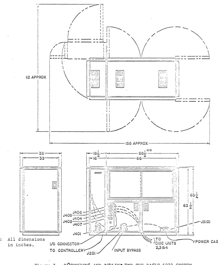
1All dimensions in inches.
~I ~---155APPROX---~----~'~
"yPOWER CABLE
Figure I. Dl1ffiNS10NS AND eM3LIN{; "FOR THE BAS'Ie 5022 SYSTEM.
*
This switching module is only installed if more than one Disc Unit is used.2.2.3
'2.2.4
2.2.5
Sheet 6 of 33
Weight
Disc Unit Logic Unit
2575 Lbs. 490 Lbs.
2.2.3.1 Floor Loading
Disc Unit Logic Unit
107 lbs/square foot 33 lbs/square foot pad loading
134 lbs/square foot 122 lbs/per caster
2.2.3.2 ' Shipping Weight
Cooling
Add approximately 100 lbs. for the Logic Unit and 200 lbs. for each Disc Unit for necessary equipment and packaging.
The top and bottom of the Disc Unit are cooled by separate air currents. The top compartment is cooled by air drawn in from the top of the unit and exhausted through both sides. The bottom compartment is cooled by air which is drmvn in on one side of the unit and exhausted on the other. The air exhausted on the side facing the Logic Unit escapes through the top of the Logic Unit. The Logic Unit also has its own supply of air which is drawn in through the side and is exhausted through the top.
Power Requirements
The basic system utilizing one Disc Unit and one Logic Unit requires 4.5 KW, 3-Phase, wye
con~ected AC power. Each additional Disc Unit
requires 3.5 KW. The system operates from 208 volts, ± 10% and from 60 cps ± 1 cps line frequency. At customer option*, the system can operate from 385 or 415 volts,
±
10% source and a 50 cps ± 1 cps line frequency. The frequency variations specified above may occur either transiently or steady state.2.2.6
2.2.7
2.2.5.1
2.2.5.2
2.2.5.3
Start Current
'The start current of th~ basic system shall not exceed 35 amps on any line of the 3-phase input and shall last for less than 30 seconds.
Run Current
The run current shall not exceed 15 amps on one line nor 10 amps on either of the other two lines.
System Power Control
The Logic Unit contains relay control circuitry to sequence the starting of the Disc Unit. It requires approximately six minutes for each Disc Unit to sequence up.
Disc Rotational Speed
The discs are driven at a rotational speed of 1200 RPM nominal. Induction slip may account for a rotational speed decrease of not more than 5% (60 RPM). (For 50 cps units* the" rotational speed is 1000 RPM with a maximum decrease due to induction slip of 50 RPM).
Physical Mechanization
There are 18 ~iscs in the disc rotation
assembly; two of these are baffle discs. The top baffle contains pre-recorded timing infor-mation accessed by a fixed head assembly. The data tracks on the remaining 16 discs (256 concentric tracks per disc surface divided into two zones of 128 tracks each) are accessed by means of gas lubricated, slider bearing heads mounted in fixed positions on a moveable arm. The arm is part of a mag-netically-actuated positioner which moves the arm to a selected position. The file can be supplied with less than 16 data
discs,m~ the minimum complement of data
discs is four.
*
At the customers option.2.2.7.1
2.2.7.2
2.2.7.3
2.2.7.4
Sheet 8 of 33
Positioners Per File
There are 16 positioners in the DISCfILE; each positioner accesses all 512 tracks on one disc.
Heads Per Positioner
There are 8 heads per positioner. Four heads are used for the upper surface and four for the lower surface. Two of the four heads on each surface access the tracks of the inner zone and the other two heads access the tracks in the outer zone.
Positions Per Positioner
There are 64 positions for each positioner.
Tracks Per Positioner
Eight tracks may be accessed per position, since each of the eight heads accesses its own track.
2.3 Single Access Channel
The basic system contains all circuitry required to transfer data to or from a particular record location. Only one read/write head on one positioner is enabled at anyone time.
2.4 System Cabling and Connectors
2.5 Compressed Air Option
2.5.1
2.5.2
2.5.3
2.5.4
2.6 Color
An. exte'rnal source of compressed air is required only when the compressor contained in the file is not used.
Air Pressure: 40 to 175 psi.
Volume: 4.5 c fm minimUlll.
Filtration: External water trap and 10 micron filter.
2.5.4.1 Recommend8d fil tratio,n media:
Filter F300-A with Cartridge F-113A.
All exterior sheet metal surfaces of the Logic Unit and Disc Unit will be supplied coated with either: zinc chromate primer) or paint specified by ~ Ot"'C
Prs€h:lst-s. Q\""-,,c
I
I$\.' (\1 It (_
3.0 FUNCTIONAL DESCRIPTION
3.1 Address Format
Records are identified and selected by means of a
recs~d identification address. This address consists
of ~ bits separated into five fields. This complete address is stored in the Logic Unit and compared with the data read from headers. A header is a pre-recorded address stored with the record in each sector. Each record in the file is uniquely identified by one of
these headers.
3.1.1 Disc Field
This field consists of six bits in the most significant address positions. The two most significant bits are used to select one of four sets of 16 position~rs and thus, one of four Disc Units in a maximum system
3.1.2
3.1.3
3.1.4
3.1.5
Sheet 10 of 33
Position Field
This field consists of six bits in the next most significant address positions. This
field is used to select one of the 64 possible positions of the selected positioner. Each position has access to eight tracks.
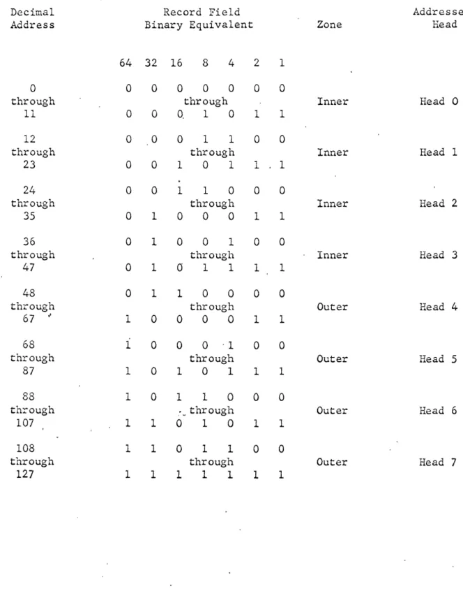
Record Field
This field consists of seten bies in the next most significant address positions. This field is used to select one of the
records associated with the selected position. The record is selected by selecting one of
/'
the eight heads and one of the;sectors
associated with tha~ head. The head address tabulation for a track pair of 32 is shown
in Table I. II
Read Next Sector Field
This field consists of one bit in the second least significant address position. This field is used as a cOITmand to the file and is not written as part of the header address. The functions executed are as follows:
3.1.4.1
3.1.4.2
Read Next Sector Field ZERO
The complete address is used to select a record.
Read Next Sector Field ONE
A partial address is used to select the first available record from a selected track. The partial address consists of that portion of the address required to select a head and thus a given track.
Parity Field
The parity field consists of one bit in the least significant position. It is a bit which makes the address have an odd number
of ONE's. It is not used as part of th~
Table I. Head Address Tabulation for Track Pair of 32.
Decimal Record Field Addressed
Address Binary Equivalent Zone Head
64 32 16 8 4 2 1
0 0 0 0 0 0 0 0
through through Inner Head 0
11 0 0 O. 1 0 1 1
12 0 0 0 1 1 0 0
through through Inner Head 1
23 0 0 1 0 1 1 1
24 0 0 1 1 0 0 0
through through Inner Head 2
35 0 1 0 0 0 1 1
36 0 1 0 0 1 0 0
through through Inner Head 3
47 0 1
a
1 1 1 148 0 1 1 0 0 0 0
through through Outer Head 4
67 " 1 0 0 0 0 1 1
68 1 0 0 0 '1 0 0
through through Outer Head 5
87 1 0 1 0 1 1 1
88 1 0 1 1 0 0 0
through :_, through Outer Head 6
107 1 1 0 1 0 1 1
108 1 1 0 1 1 0 0
through through Outer Head 7
Sheet 12 of 33 3.2 Sectors and Sector Organization
The Disc Unit is supplied with inner zone tracks of 1/12 equal sectors per track and outer zone tracks of
',20 equal sectors per track, thus the standard system is a track pair of 32~1 At the customer's option, track
pairs of 16 (6 and 10) or 8 (3 and 5) can be supplied.
3.2.1 Sector Organization
The sector format is determir.ed by the number of coded sector characters recorded on a single sector control 'track. The total nUfaber of bits per sector is determined by t~e nlliliber of
sectors per track and the nurC,0er of clock bits for the zone which contains the sector. The cotal numqer of bits per sector, ,in eithe~,/
zone) i-s· ~i 7 4·2--B-s:iI';g~;r~k -puLc....:.o { ·32 ~ (
(-For
track pair-s of--16 "and 8·,--the. total-number of -bit-s is-34:84-and-6968-·r-e-spe€-t4-v-e+y-.) Each sector consists of a header containing the record identification address followed by a record containing the stored data. Additional space before the header and between the header and the record is used to acco~uodate mechanical tolerances, including the erase-to-read/write gap. Both the header and the record are pre-ceded by a sync bit (ONE) to identify the beginning of the data.3.~.1.1
3.2.1.2
The Header
The header contains 1·9 bi ts. The read next sector and parity bits are not recorded in the header. In place of these bits, two ZERO bits are recorded (following the sync bit) so that the header has the same number of bits as the address (for comparison during track confirmation and record validation).
Record Length
3.3 Control Tracks
There ~re four independent sets of control tracks. Each set consists of four control tracks. These tracks are located on the top baffle disc and are pre-recorded by Data Products Corporation. Data Products Corporation retains records of customer control track requirements to enable recording of new control discs.
3.3.1
3.3.2
3.3...3
3.3.4
. 3.3.5
One control track contains clock information used to generate clock pulses for inner zone writing. This track contains 20,904 bits
and is recorded with a one-bit maximum anomaly at the splice point.
The second control track contains clock information used to generate clock pulses for outer zone writing. This track contains 34,840 bits and is recorded with a one-bit maximum anomaly at the splice point.
The third control track contains ch~racters used to define the beginning of each track and to locate each sector within the track. There shall be a minimum of four ZEROS
betw~~n any two characters. Index) inner
zone, and o~tey zone sector c~aracters are pre-recorded on this track at a frequency of 500 KC and are identified by means of a 4-bit character code as follows:
Index Character - 1111
Outer Zone Sector Character - 1011 Inner Zone Sector Character - 1101
. The fourth control track contains a single revolution index character (four O~ES in a
track of ZEROS). This track is normally used as the index reference mark for main-tenance purposes .
sheet 15 of 33
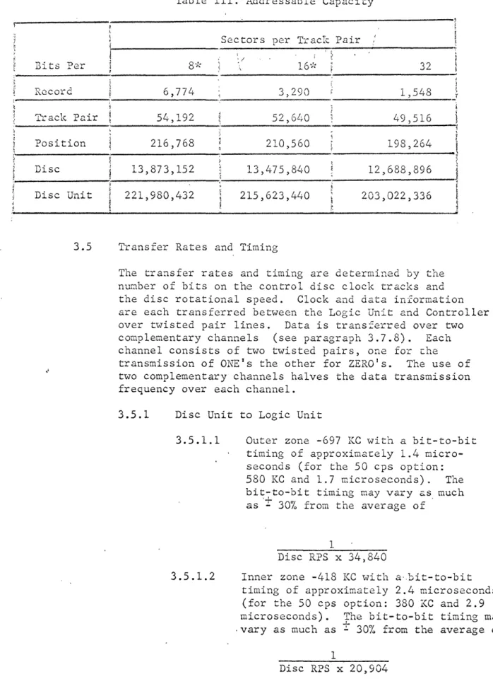
Table III. Addressable Capacity
~---~----·---~---l
~
________________._S_e_c~t_o_r_s~p_e_r
__T_i_~a_c_l~~~,_p_a_i_r
__~
____________ J? ~
32 i
Bits Per
I
~ (
I
l __ --h-iQ-c-o-r--d---~---6-,-7-7-4---~---3-,-2-9-~-Q ________________ 1~,~5_4_8 ____
j
T"'..:-ack. Pair 54,192 52,6£,0 49,516
Position 216,768 210,560 198,264
Disc 13,873,152 13,475,840 12,688,896
Disc Unit 221,980,432 215,623,440 203,022,336
3.5 Transfer Rates and Timing
The tra~sfer rates and timing are determined by the
nunber of bits on the control disc clock tracks and the disc rotational speed. Clock and data information are each transferred between the Logic Unit and Controller over twisted pair lines. Data is trans~erred over two complementary channels (see paragraph 3.7.8). Each channel consists of two twisted pairs, one for ehe transmission of ONE's the other for ZERO's. The use of two complementary channels halves the data transmission frequency over each channel.
3.5.1 Disc Unit to Logic Unit
3.5.1.1
3.5.1.2
*
At the customer's option.Outer zone -697 KC with a bit-to-bit timing of approximace1y 1.4 micro-seconds (for the 50 cps option: 580 KC and 1.7 microseconds). The bit-to-bit timing may vary as much
'+ '
as - 30% from the average of
1
Disc RPS x 34,840
Inner zone -418 KC with a-,bit-to-bit timing of approximately 2.4 microseconds (for the 50 cps option: 380 KC and 2.9 microseconds). The bit-to-bit timing may
..l--vary as much as ~ 30% from the average of
1
3.5.2 Logic Unit to Controller
3.5.2.1
3.5.2.2
Outer zone-291 KC for each channel of the complementary pair with a bit-to-bit timing of approximacely 2.8 microseconds (for the 50 cps
option: 242 KC and 3.4 microseconds).
Inner zone-174 KC for each channel of the complementary pair with a bit-to-bit timing of approximately of 4.8 microseconds (for the 50 cps option: 145 KC and 5.8 microseconds).
3.6 ,Access Times
The time required to access data depends on cne positioner power status of the file at the time the o?eration is requested and upon the length of the stro~2 required to reach the selected track . . The follo~ing paragraphs define the Various components of access time.
3.6.1
3.6.2
3.6.3
Disc Unit Switching Time
This is the time required (in a syscem using more than one Disc Unit) to switch from one Disc Unit to another. This time is 5 milli-seconds minimum. ' "- \", \, !
Power Switching Time
When the positioner is in the "povler holdlt status and a new disc and/or posi~ion is requested, power switching time is required. This is the time between a power of: pulse for one positioner and the power on pulse for a new positioner. The time required is an average of 26 milliseconds but may vary from 20 to 30 milliseconds. When the file is in the power
off status, the power switching time for a new address is seven milliseconds minimum'.
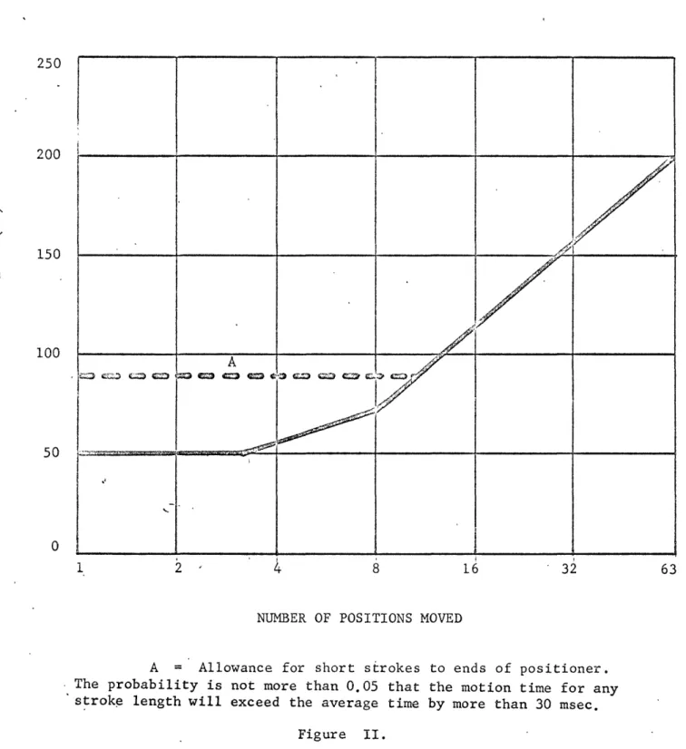
Positioning Time
3.6.4
3.6.5
Sheet 17 of 33
Confirmation is complete when this has been accomplished. A minimum of 39 milliseconds
(for 50 cps, 47 milliseconds) must be allowed for confirmation. The motion time shall not exceed 225 milliseconds and shall be consistent with the values shown in Figure II.
Latency
Latency time will vary from a minimum of one sector time to a maximum of one disc revolution. Average latency is one-half a disc ~evolution.
Minimum latency is always achieved in the read next sector mode.
Minimum Latency
Inner zone: 4.3 ms (50 cps: 5.3 ms) Outer zone: 2.6 ms (50 cps: 3.2 ms)
Maximum Latency
52 ms (with slip) (50 cps: 63 m~) Average Latency
26 IDS (50 cps: 32 ms)
Head Switching Time
The total head switching time (including read amplifier recovery time) is a nominal 100 micro-seconds. This time does not affect access time
s~nce i t is much shorter than the
electro-mechanical times which occur.
3.7 Control Signals and Operation Sequence
3.7.1 Select (Controller to Logic Unit)
The Select pulse logically prepa~es t~e Logic Unit to receive and store an address and
clears all data and sequence error conditions. The Select pulse must always be followed by an address; it is usuallY,sent following the end of a completed read or write operation. However, it is permissible to send a Select pulse followed by a new address after Address Termination
z
o
H
!H
o ::s
250
200
150
100
50
o
/
./
A
'I~ c.~,J ~ G.::O '.G eo C':) C13 f.''3 c.;..:::) Q;;) ~ &::;..I~ ~ ~ /...4
~
~
.'
1 2 8
~
j /
I
16 . 32
NUMBER OF POSITIONS MOVED
A Allowance for short strokes to ends of positioner • . The probability is not more than 0.05 that the motion time for any
. strok~ length will exceed the average time by more than 30 msec.
Figure II.
3.7.2
"
Select pulse sent after Address Ter~inntion
but before Rea~y (pnragraph 3.7.4) causes
a
seck interrupt which automatically interrupts the seek operation being executed. The Select pulse shall not be sent between the Alert pulse and the End pulse (paragraph 3.7.10).The tir'..1e required to, execute a seck interrupt depends upon 11m" far tli....: ~ ... ~.~rrupted seek operation has progressed. W~en the new Select arrives before the posicioner is set in motion, the file im~ediately begins to operate on the new ndGress. Hhen the n2\" Select is received after the positioner is set in motion, there is a delay. before the new address is operated upon. This delay is dependent u?O~ ~he time the file has spent operating upon the Old address but shall not exceed a nominal 250 ~illiseconds.
The delay is required to ensure ~~at power is not removed from the positioner while it is in motion.
Address (Controller to Logic Unic)
The address of the record that the Controller is seeking is sent serially over the Even Data complementary channe+. Address bits will be
sent in. the following order: addre'ss ·parity ·bit, \
, I ! \ ( ~ ! ' ( J l I ,
re~d\n~xt sector'~it, record field, posttio~ field,
and"d'isc "ffe'ld with the least significant bit of each field first.
Address transmission shall not begin sooner than 5 microseconds after the Select pulse has been sent. The rate of transmission is determined by the controller and is 750 KC maximum.
The complete address is stored in the Logic Unit. The address is checked for parity and correct length. After the transmission of. the address
i~formation, an Address Termination pulse is sene
which disconnects the file system from the
Controller. The read next sector field is stored <.·,nd interpreted by the Logic Unit to select the full address or the partial address for record selection.
\ \
3.7.3
3.7.4
Termination pulse is rQceiv2d. ~he stored address is used to sclect a positioGer, move that positioner to the selccccd position and select a head for re~ding headers (A header is a unique code sto~ed in each sector to identify each record). A sufficien~ numoer of headers from the selected tr~ck are read to determine that the positioner is settled on the tr&ck. After the desired address is found, the file system is pre?8red to perform a read or write operation. The Lime to locate the address sought is conditioned by the read next sector bit, since a full &ddress compare is performed only if i t is a ZERO.
Address Termination (Controller to Logic Unit)
The Address Termination pulse is sent over the
ONE twisted pai~ of the O~d Dat~ c9~plement&ry
channel (see paragraph 3.7.8), lO ~ 9 mi~ro
seconds after the last bit of ~ne address is sent to the logic Unit. This pulse logically disconnects the Logic Unit from th~ Controller and initiates the seek operation.
Ready (Logic Unit to Controller)
The seek operation terminates with the trans-mission of,a single Ready pulse to the Controller
, , I ~ ... j , .1, • • \ ' . "\ \ " ' ; .
over the tw~sted pa~r llsed to rece~ve the Clear pulse. , This pulse is generated after the
positioner has settled, and the address stored in the Logic Unit agrees with the address read from a header. This pulse indicates that the read/write head is located in the sector
immedi-ately prior to that in which reading or writing may be performed.
Wnen the read next sector bit is a ZERO, the Ready pulse is sent to the Controller at the end of the header which cOillpletely agrees with the disc, position and record fields of the address stored in the Logic Unit. If the
Con-trolle~ does not respond to a Ready with an
3.7.5
3.7.6
If the read next sector bit is a OX':) then the Ready pulse is sent as soon as the positioner is settled on the track. The Ready pulse is then sent after each header is ~e&d until an Alert pulse is received. wnen headers are written from the Controller, the Ready pulse
indicates that the positioner has settled at the selected position.
Alert (Controller to Logic Unit)
The Alert pulse logically prep~res a Logic Unit to receive a Read or Write pulse.
The Alert pulse shall follow :he Ready pulse by 2 microseconds miniml:n1, 2 milliseco:'-lds maximum. The Alert pulse causes the Logic U~it to incre-ment the stored record adcress by one. Then, the header associated with the reco~d to be operated on is compared with ehe iGcremented address, the extent of the com?sre riepending on'the read next sector bit. Rence, the address of the record in which t~e read or
write operation will be perfor~ed is the address originally received from the Controller augmented by one.
Read (Controller to Logic Unit)
The,Read pulse shall follow the Alert pulse by
10 T 9 microseconds and prepares the file for a read operation.
The Logic Unit commences to transm~t the data read from the addressed record. wnen the Con-troller has received sufficient data, i t may disregard further read signals, however, i t cannot properly terminate the flow of data unless i t sends an End, Read or Write pulse. A Read or Write pulse given before the end of the record will terminate data transfer and the read or write operation will be performed in next s~ctor; an End will terminate communication.
After the selected record is read, a time slot (8 microsecond,s) is available to tell the file whether the operation is to terminate or continue.
3.7.7
just read will then be read. This operation of"reading the following record r.1.:ly be repeated so that all records which correspond to a given position are read sequentially. The file system can execute this mode of operation indefinitely. If a Write pulse is sent during this time slot, the record address will be incremented and a write operation will be performed in the next
sector.
Write (Controller to Logic Uui~)
jThe,Write pulse shall follow t~e ~lert pulse by 10 T 9 microseconds. The Co~~roLler chen responds to the Logic Unit Write Clock pulses vlith write data pulses.
After the selected record is written, a time slot (8 microseconds) is available to tell the file whether the operation is to terminate or - continue. An End pulse terminates the '\VYite
operation. If a Write pulse is sent during this time slot, the address stored in the file is incremented by one and the next record following the One just written is w£itten a=ter a favorable compare. This operation of writing ~he following rec.ord may be repeated so that .:..:"1 records which correspond to a given position may be written ,sequentially. The same method
0=
sequentialaccessing is used for write as is used for read.
I~ is importan~ that the Controller ~ee? count
of. the number of records sequentially written at one position to avoid destroying data not yet read.
A Write Check mode is also available in the Logic Unit. This mode is enabled by issuing a Read pulse during the record or in the time
s16~ following t~e record just written. The
Read pulse does not increment ~he address. This mode thereby constitutes a write-check
con~inue, since the Logic Unit iLcrements t~e
stored record address by one if given another Write pulse, the operation may be continued
through all the continuously addressable records at one position.
3.7.8
3.7.9
Sheet 23 of 33
Complementary Data Channels (Controller to Logic Unit and Logic Unit to Controller)
There are two complementary data- channels; one is the Odd Data Channel and the other is the Even Data Channel. Each channel contains two twisted pairs; one for trans-mission of ONE's and one for transtrans-mission of
ZERO's. On each transmiS~~0~ of a bit, one, and only one twisted ,pair shall be pulsed. Furthermore, data transmission alternates between complementary channels and there must not be con-current transmission on both channels. The direction of transmission on these channels depends upon whether the file system is reading or writingo
When reading, the Logic Unit transmits
the information read over these cha~nels. Each channel is pulsed al~ernately with the first bit of each record being transmitted over the Odd Data complementary channel.
During the write operation, the Controller
transmits pulses over these channels in response to Clock pulses sent by the Logic Unit. The Clock p~lses are gated back on the Odd or Even complementary data ... channel as ONE I S or ZERO's
over the appropriate twisted pair, in 0.4 to 1.0 microsecond. The delay time is determined by the propagation time of the line and the Controller delay and is measured at the file interface.
The time between two consecutive data pulses when reading may vary by
±
30% from the average data rate, as defined in paragraph 3.5.1.Write Clock (Logic Unit to Controller)
The Write Clock pulses are sent to the Controller on two twisted pairs (odd and even). The first clock pulse is transmitted on the odd twisted pair. The Write Clock pulses start when the head reaches the portion of the track to be written. The pulses terminate with the receipt
of an End, Write, or Read pulse. If an End pulse is received, no more data is to be
3.7.10
3.7.11
3.7.12
End, Read, or Write pulse is received before the reco~d is completely written, ZERO bits are automatically written in the remainder of the record.
The c16ck pulses are generated from information read from the control disc clock tracks.
End (Controller to Logic Unit)
The End pulse is sent by the Controller to discontinue communication. The End pulse also disconnects the Logic Unit from the Controller and the file is then ready to receive a new Select command. Upon receipt of the End pulse, the Logic Unit transmits no more than one clock pulse or dat~ bit. The End pulse may be given at any ti~e during the record. If co~~unication
is to be terminated after a record, the End pulse must be sent during the 8 microsecond guard slot.
Clear (Controller to Logic Unit)
The Clear pulse is sent on the same twisted pair used for Ready. This pulse is used if it is desired to interrupt the "power holdlr state of the file system. The positioner circuits of the file system are designed so that the heads remain on the tracks at the position selected until a Clear pulse or master clear level· is received or a new disc and/ or position is selected.
The End pulse is also used to gate the Clear pulse into the system. The Clear pulse shall be transmitted to the Logic Unit no sooner than the End pulse, and no later than 2 micro-seconds after the End pulse.
Lockout Warning (Logic Unit to Controller)
3.7.13
3.7.14
3.7.15
Sheet 25 of 33
If the Controller attempts to write data, data writing or erasure is inhibited and a Data Check error (paragraph 3.8.12) is genera~ed.
Master Clear (Controller to Logic Unit)
This signal removes power from the positioner currently accessed and then clears all internal logic. The signal is supplied over
a
twisted pair which is normally an open circuit. Contact closure from the Controller i~itiates the master clear function.Operable (Logic Unit to Controller)
This signal is sent over a twisted pair which is a closed circuit when the storage system is operable. Power is first applied to the Logic Unit and the Disc Unit (or units) by depressing the Power On pushbutton on the Logic Unit. When the Logic Unit (and its associated Disc Units) is operable and avail-able to receive ~ommands from the Controller, a relay contact closure indicates Operable.
The Operable signal is terminated: by depressing the Power On pushbutton on the Logic Unit;
placing the Logic Unit or Disc Unit in test mode; when the positioner power supply output in the Disc Unit falls below normal; or when an over temperature condition is detected.
Alarm (Logic Unit to Controller)
This signal is'sent over a twisted pair which is open-circuited if operation is normal. The Alarm signal is indicated by the closing of a relay contact if the ambient. temperature in the
storage system, (Logic Unit or Disc Unit) reaches the alarm level, or when any of the test mode switches is in a test position during the normal operate mode or when a malfunction in the flying head air supply is indicated. The signal is also active when the positioner power supply fails or when an oVer temperature condition is detected;
3.8 Error Signals
An error pulse is transmitted to the Controller in
response to any of the error conditions to be discussed. The Logic Unit contains a FAULT indicator on its external control panel which lights when a sector or positioning error occurs. Each of the error condicions are indicated by sep'arate lamps on the internal mair.tenance panel. A new Select pulse clears all data and sequence error
conditions. Electro-mechanical malfunctions) as indicated by the Alarm signal) cannot be reset electronically but require manual interruption.
3.8.1
3.8.2
3.8.3
3.8.4
Address ,Pari ty Error
This error condition exists if the ad¢ress parity bit as received by the file does not give odd parity to the address transmitted. Address parity is checked when the Address Termination pulse is received. If an address parity error exists, an Error pulse is transmitted to the Controller, and the PE (parity even) error indicator is lit.
Address Termination Error
If the Address Termination pulse is not received at the time specified in 3.7.3) an Address
Termination error exists. An Error pulse is sent to the Controller approximately 30 micro-seconds after the last bit of the address is transmitted) and the AT (address termination) indicator is lit.
Incomplete Address Error
If the Address Termination pulse is received before the complete address has been trans-mitted; an Incomplete Address Error exists. An 'Error pulse is sent to the Controller and
the IA (incomplete address) indicator is lit.
Address Transfer Error
3 .. 8.5
3.8.6
. 3.8.7
3.8.8
Sheet 27 of 33
are transferred in parallel to a storage register. The contents of the storage
register and the portion of the shift register which was transferred are then compared with
the exception of read' next sector field. If they do not agree, an Address Transfer Error exists. An Error pulse is transmitted to the Controller and the T (traqsfer) indicator is lit.
End Error
If, after reading or writing a record no End, Read, or Write puls~ is received during the provided guard slot, an End error exists. An Error pulse is 'transmitted to the Controller and the END indicator is lit.
Write Clock Error
During ~ Write operation, pulses from the clock track used for ge~erating Write Clock pulses are checked to see that no pulses are missing. If a pulse is missed, a Write Clock Error exists. An Error pulse is sent to the Controller and the
we
(write clock) indicator is lit .Positioning Error
When a seek operation is initiated, and is not terminated approximately 600 milliseconds later by the positioner settling down, a Positioning Error exists. An Error pulse is transmitted to the Controll~r and the DP (disc position) and the FAULT indicators are lit.
Sec tor Error
The Sector Error condition exists if, approximately 120 milliseconds after the positioner is settled, the desired record cannot be found. This condition would prevent a Ready pulse from being transmitted. Also, if, after the file has been alerted and
conditioned to read or write the file is unable to match the header address with the stored address,
3.8.9
3.8.10
3.8.11
3.8.12
Data-In Error
This error exists, while writing in the file, if any two successive data pulses received are separated in time by more than 150% of the normal time separation. Both complementary data channe1sare examined for this condition. The error condition sends an Error p~ls~ to the ,Controller and lights the DI (data in) indicator.
Data-Out Error
This error ,exists, while reading from the file, if any two successive data pulses sent are separated in time by more than 150% of the normal time spearation. Both complementary data channels are examined for this condition. The error condition sends an Error pulse to the Controller and lights the DO (data-out) indicator.
Clock Check Error
A clock check error is generated when, during a write operation, an odd or even clock pulse is dropped, an outer zone even clock is gener-ated during an inner zone operation, or a write amplifier malfunction is detected. Any of these ,conditions results in an error pulse to the Controller and lights the CC (clock check) indicator. '
Data Check Error
During a write operation, a bit-by-bit
compari-~on is continually made betwee~ the data trans-mitted by the Logic Unit and the data content of the write current. Bad com?arison results in an error pulse to the Controller and lights the DC (data check) error. This error will also occur if an attempt is made to write on a looked~ out disc.
3.9 Equipment Life
3.10
3.11
Sheet 29 of 33
Errors Warranty
There shall be no errors due to failure of the magnetic recording medium (bad spots) for the warrantable life of the equipment assuming that recommended maintenance procedures are followed. In addition) the equipment shall not exhibit any magnetic degradation with time of pre-written data sufficient to cause errors while reading.
Design Objectives and
t.~f~-:e. '-~-~ror
RatesThe following paragraphs define the design objectives and acceptance error rates of the,DISCfILE system. The system. shall be accepted by the cus~omer on the basis of criteria defined in Data Products Corporation acceptance test specification Number 102254.
3.11.1 Malfunction Definitions 3.11.1.1
3.11.1.2
3.11'.1.3
3.,11.1~4
Reading Error
A data error is detected and three repeated reading opera~ions initiated either automatically or under program control) are error-free.
Writing Error
A data error is detected as the result of a write check* and three repeated writing operations) followed by write checks initiated either automatically or under program control are error-free.
Incomplete Operation Error
A malfunction of the equipment 'occurs during which there is no data error. Either automatically or under program control) the operation is repeated and is completed successfully.
Failure
A condition which causes errors or other malfunctions which can only be corrected by unscheduled maintenance.
3.11.2
3.11.3
The design objectives of the system for field ?peration are listed below.
NOTE
The following failure and error rates are design objectives for the equipment wh~le operated in a typical commercial computer environment.
3.11.2.1
3.11.2.2
3 .. 11.2.3
3.11.2.4
Incomplete Operation Error Rate
Not more than 1 in 105 operations.
Reading Error Rate
Not more than 1 in 1010 data bits transferred.
Writing Error Rate
Not more than 1 in 5 x 10¹⁰ data bits transferred.
Failure Rate
Not more than 1 failure for 250 hours of cumulative file operation.
1 i
~....z/v'i-1:-""',-,-,,;~,-. { • .(.~,
Accep~.rr~e-Test Error Rates _ 1.
1.,:-,:.
f ' I/'l..~" C.l:.i...A/... \
~·vrc"),"""'\(l;..~"d"':- . ____ ...l... t
-Following are .th~acceptance test criteria~ f~
th~re.dellve-ry- aceeptance···'te'st-·'Performed
at D~ta"Products-,Corp-or'ation.
3.11.3.1
3.11.3.2'
3.11.3.3
Incomplete Operation Error Rate
Not more than 1 in 2 x 10⁴ operations.
Read Error Rate
Not more than 1 in 2 x 10⁹ data bits trans ferred.
Write Error Rate
Sheet 31 of 33
3.11.3.4 Failure Rate Four. maximum
4.0 INTERFACE CHARACTERISTICS
4.1
Controller to Logic Unit Interface4.1.1
4.1.2
Electrical Characteristics
All communication between Logic Unit and controller shall be by O.S-microsecond pulses over twisted-pair transmission lines with a characteristic impedance of approximately 100 ohms, each twisted pair constituting one channel. The O.S-micro-second pulse, ± 20% at the 50% crossover point, shall have a rise time of 0.1 microsecond maxi-mum and a fall time of 0.1 microsecond maximum. The pulse amplitude shall be 5.5
t
1.3 volts at the receiving end, and the noise shall have a rise ,time of less than 2 volts per microsecond. The aforementioned Signal characteristics shall ,be over a maximum cable length of 100 feet betweenthe Controller 'and the Logic Unit (interface). Data Products Corporaeion shall supply a termin-ation plug with each Logic Unit.
Interface Pulse ~ignal Summary
4.1.2.1
The following 14 signal twistedpairs constitute the pulse interface. Each has the characteristics defined in paragraph 4.1.1.
Select
Even Data ONE's , (Addlress) Even Data ZERO's
Odd Data ONE's (Address Termination) Odd Data ZERO's
Ready (Clear) Alert \
Read Write
Wr i te Clock Odd Write Clock Even End
Error
4.1.3
4.1.2.2 Three additional signals are provided by relay closures:
Operable Alarm
Master Clear
Interface Wiring (Controller to Logic Unit)
The cable between the Controller and the Logic Unit (supplied by the customer) shall be
constructed in the following manner:
4.1.3.1 .
4.1.3.2
4.1.3.3
4.1.3.4
Signals shall be transmitted over pairs of twisted conductors.
Each Conductor shall be #18 AWG stranded wire covered with 600-volt insulation.
Each pair shall be twisted a m~n~mum
of 12 turns per foot of cable length.
Each twisted pair shall be terminated in the Controller by approximately 100 ohms.
The twisted pairs are grouped below together with the pin numbers on the connector in the Logic Unit (Connector J401 in Figure
I).
B4 B2
Cl C3
C5 C7
C9 Cll
D4 E5
D14 E15
Alert
+
AlertSelect
+
SelectWrite Clock Odd
+
Write Clock OddWrite Clock Even
+
Write Clock EvenData
'a'
Odd+
Data'a'
OddData
'a'
Even (Address) Data'a'
Even (AddressEl Data ' l' Odd/Address Termination D2 Data ' I' Odd/Address Termination
Ell Data '1' Even (Adress)
+
D12 Data 'I' Even (AddressF2 Read
+
F4 ReadF6 Write
+
F8 WriteFlO End
+
F12 End+
H2 Ready/Clear+
H4 Ready/ClearLl L3
L5
L7
5.0
Sheet 33 of 33
Alarm
+
M2 Error+
Alarm M4 Error ~
Master Clear
+
S6 Operable+
Master Clear Sl OperableU9 Write Lockout Warning
+
Ull'. Write Lockout Warning
MAINTENA..'I\CE
5.1 Scheduled Maintenance
Routine scheduled preventive maintenance procedures will normally require about 8 man-hours per mo~th. This main-tenance should be performed by suitable trained and competent customer personnel. The schedule for routine preventive maintenance shall be in accordance with the preventive main'tenance procedures recoramended by
Data Products in the instruction manual and Customer Information Bulletins.
5.2 Unscheduled Maintenance
5.3 Spare Parts