-, f
':
The Magazine of
I
I
L
i:
/
\.,;
I
I I It ..
r!'J
January / February
...,...---~
-~-.---,---1~.7~~~:.>~'-~~~;~,~\o:\
' .
~!tBa
'8UJOt{+/>'l'BH. opuwas
tnt
riI
10VI.
~n:
f.n::
.!\.~a S01uo.!~oetm:·
f -: - . . ':aGE:
t{s"eO
1~13tiI
:1)?JtJ.~(~.~:~~:I
ro.Id
4111=9"[51
~
putUll'Pm: '
)_. :-
,.:-=(:\:/~\:~___ . _
... ___ .... __ . __ _._
._._0' .. __ , __ c .••. _ .. __ . _ _ . .BlearCh
~tngineering
A SMALL, TRANSISTORIZED UNIT FOR SYSTEM COMPATIBILITY IN:
data processing,
com-puting and automation systems. Another member of Telemeter Magnetics' growing
family of coincident current magnetic core storage buffer units, this neatly designed
package containing storage capacity for 1152 binary digits, switching and driving
circuitry to load and unload information and a self-contained power supply, measures
only 8% inches high and 14 inches deep in standard relay rack mounting. Like the larger Telemeter Magnetics
buffers, it is designed to provide compatibility between two data systems having different operating characteristics.
Pioneer work in the development and manufacture of magnetic core storage buffers has made Telemeter Magnetics
a specialist in this field. Call them in to solve any memory or buffering problem, or for specific information
reg~rdingthe 144-BQ8 or the 1092 series
of
buffers, write:
o/i
TELEMETER.
MAGNETICS
Inc.
2245 Pontius, Los Angeles 64, California
For use as: delay,
<l
A~ A~ ~2)
U' D
~f))
temporary~torage
Olj
I
{~
J(!J1
D ) , ) ,
((~)
buffer, specify the "",...:l!
r:::....
\JJ(,~/SPECIFJCATIONS: Number of characters: 144: Number of bits/characters: S", loaded or unloaded simultaneously; Loading or Unloading Speed: 14 JJ. sec/character: ~olid state compoRents only: Signal Amplitudes: Input: ZERO-S Vdc, ONE+S Vdc, Output: Pulse: ZERO-5V, one +Sv. Load Sync: +10v, Unload Sync. +10v. Power: 1 amp at 115v, 60 cps.
trAvailable in 4 bit model, specify 144-BQ4
DATA
the automatic handling of
information
volume
4,
number
~..,
OVER 23,000 CIRCULATION
Research & Engineering is circulated without charge by name and title to the manufacturers and users of automatic information-handling equipment in all branches of business, industry, government and mili-tary installations. Qualified individuals in the United States and Canada are invited to request this publi-cation on their company letterhead, stating position and the firm's business. Available to others by sub-scription at the rate of $10.00 annually; single issue, $1.00 when available. No subscription agency is authorized by us to solicit or take orders for sub-scriptions in the U. S. or Canada.
Published bi-monthly by The Relyea Publishing Corp., Frank D. Thompson, president. Executive &
Circulation office: 103 Park Ave., New York 17, N. Y., LExington 2-0541; Editorial & Advertising office: 10373 W. Pico Blvd., Los Angeles 64, Calif., BRadshaw 2-5954. Unsolicited manuscripts must be accompanied by return postage; although all rea-sonable care will be taken, the editor assumes no re-sponsibility for their safety or return. Published and accepted as controlled circulation pUblication at Los Angeles, Calif. Copyright 1958, The Relyea Pub-lishing Corp. The trademarks R;E and Research &
Engineering are the property of The Relyea Publish-ing Corp., registered with the U. S. Patent Office.
FEATURES
7 Data Retrieval . . . One Solution: The Searching Selector of Western Reserve University (Cover Feature)
12 Displays for Decision - An Evaluation of Automatic Plotters 16 A Data Processing System for Low-Level Sig1lals
19 Core Buffering: An Aid to Balanced Data Flow by Ernst Jacobi, Telemeter Magnetics, Inc.
34 Some Features of the Czechoslovak Relay Computer SAPO by Jan Oblonsky
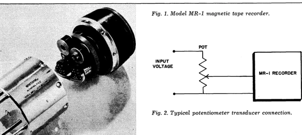
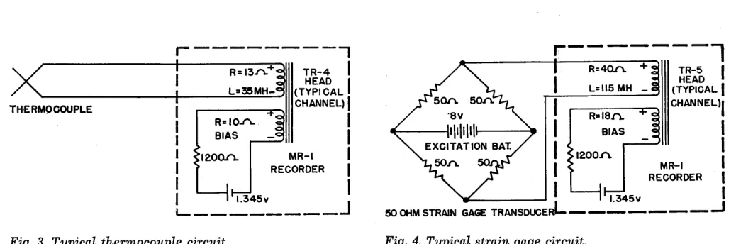
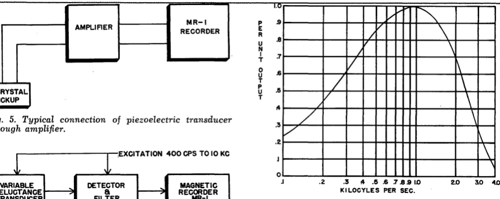
40 Miniature/Portable Magnetic Tape Recorders by Eugene Bollay, Northram Electronics, Inc.
ARTICLES
5 Clary Introduces New ECS Low-Priced Computer
IS GM Computer-Simulator Permits Car Stability & Control Study 24 An Executive Voice in Datamation: James R. Bradburn 36 Bendix Completes lOOth G-1S Computer
38 IBM's Ramacade Takes to the Road
43 Computer-Run Submarine Simulator Provides New Dockside Training 44 Experimental Device Reads Handwritten Numerals
48 Ramo-Wooldridge Develops New Memory Unit
DEPARTMENTS
II Datamation A broad
33 Datamation Book Capsules
3 Datamation in Business & Science
22
Datamation on Campus37 !mportant Dates in Datamation
45 New Datamation Literature
26
New Products in Datamation21
People Moving Up in DatamationPUBLISHER 6' PRESIDENT Frank D. Thompson
VICE-PRESIDENT Gardner F. Landon
EDITOR Charles R. Kluge
ASSOCIATE EDITOR Santo A. Lanzarotta
PRODUCTION MANAGER Dorothy B. Creeden
CIRCULATION MANAGER Martha Knowles
SALES MANAGER Earl W. Wilken
EASTERN REPRESENTATIVE Paul S. & Donald C. Weil
39-01 Main St., Flushing 54, N. Y., INdependence 3-9098 CLEVELAND REPRESENTATIVE John J. Millar
3537 Lee Rd., Shaker Heights 20, Ohio, WAshington 1-9370 MIDWEST REPRESENTATIVE Gilbert Thayer
201 N. Wells St., Chicago 6, III., Financial 6-1026 WESTERN REPRESENTATIVE Earl W. Wilken
10373 W. Pico Blvd., Los Angeles 64, Calif., BRadshaw 2-5954
2
DATA
FROM THIS
OR THIS
•
• •
• •
CAN BE
AUTOMATICALLY PLOTTED
Electronic Associates Inc.
DATAPLOTTE·R
IN ANY OF THE FOLLOWING FORMS
1. One set of data represented by successive dots on an X-Y graph.
2. Up to twelve sets of data represented by successive symbol marks on an X-Y graph, each set identified by its own unique symbol.
3.
A continuous line connecting pre-selected points to produce engineering drawings or statistical charts.Masses of invaluabl~ research clata, business statistics, and actual physical measurements Can be
quickly
presented in clear, easy-to-understand graph pictures.Write Dept. D-2
BY
ELECTRONIC
ASSOCIATES
• • • • •
MANUFACTURERS OFP A C E
9~
PRECISION ANALOC COMPUTING EQUIPMENTLONG BRANCH. NEW J E R S E Y . TEL. CAPITOL 9-1100
Ciule 2 Oft Reader Service Card
i.:.
:Ii
.~
..
DRTR
~
NEW SERVICE
BY RAMO-WOOLDRIDGE
WJCC THEME:
CONTRASTS IN COMPUTERS
IBM, TI
IN TRANSISTOR AGREEMENT
COMPANIES
JOINTLY OPERATE CENTER
MONSANTO
INSTALLS ANALOG SYSTEM
305, 608
NOW IN OPERATION
in business and science
A Computation and Consulting and Service Bureau for business
and industrial organizations has been established by the
Ramo-Wooldridge Corp., Los Angeles, Calif. It will be operated as part
of the company's digital computing center headed by Dr. Walter
F. Bauer. Consulting in computer applications and digital
comput-ing services includcomput-ing numerical analysis, programmcomput-ing, and
equipment rental, will be offered.
When the 1958 Western Joint Computer Conference convenes at
the Ambassador Hotel in Los Angeles on May 6, the first
na-tional symposium on modern computer design methods and
appli-cation techniques will take place. Leading authorities in the field
will argue the relative merits of various systems and components
under the general theme of "Contrasts in Computers."
Texas Instruments, Inc., Dallas, has signed an agreement with
International Business Machines Corp. under which both
com-panies will work together in the area of transistors for data
pro-cessing machines. The pact is expected to expedite progress in
the area of computer development through the exchange of
tech-nical information pertaining to transistors.
The agreement provides that I BM wi II purchase from TI a
substantial portion of its expanding future commerdal transistor
needs. This places no restrictions on either company's present or
future relations with other customers and suppliers.
Twelve tenants of Westbury I ndustrial park at Westbury,
L.I.,
N.Y., have come up with what might be the answer to the large
initial outlay for computers by medium and small-sized firms. In
the first known experiment of its kind, these companies are
shar-ing use of data processshar-ing equipment at a center operated bo/
Scientific Tabulating Corp. The center features $160,000 in Rem
Rand equipment and cost approximately $320,000.
Monsanto Chemical Co., St. Louis, Mo., has completed installation
of a large scale analog computer system. To be operated by the
company's research and engineering div., the computer is expected
to be a voluable tool in helping to solve mathematical equations
arising from Monsanto's study of automatic control systems for
, its chemical plants. A special facility of the computer is the
solu-tion of differential equasolu-tions found in studying automatic control
and process dynamics. problems.
First production models of two new I BM computers, the 305
RAMAC and the ,608, have been delivered to customers.
A pair of 305s, developed and manufactured at the IBM
plant in San Jose, Calif., were installed at the Denver operational
headquarters of United Airlines. They are speeding the processing
of thousands of ticket reservations made daily by the airlines' many
ticket offices across the country. Another 305 is being employed
in electronically controlled warehousing and distribution at Factory
Motor Parts, Inc., San Francisco, Calif.
4
G-T BEGINS
COMPUTER DIODE OUTPUT
POTTER CITES
PATENT INFRINGEMENT
EDP HELPS
ELECTRON TU BE BOOM
AUTOMATE
-OR DIE, SAYS M-ORAN
DATA-CONTROL
FORMED BY JEFFRIES
BURROUGHS
HAS BUSY DECEMBER '57
Production of germanium and silicon computer diodes and silicon
rectifiers has begun at a new General Transistor Corp. plant in
Richmond Hills, Queens, L.I., Rudolph Sachs, formerly with
CBS-Hytron and Clevite Transistor, is v-p in charge of the diode div.
Notice to cease infringement of his patent rights has been sent
to leading manufacturers of digital computers and data processing
systems by John T. Potter, president of Potter Instrument Co., Inc.,
Plainview, N. Y. Patent number 2,624,786, held by Potter since
1953, will affect the manufacture of approximately $100 million
worth of computer apparatus now being produced. This figure
could increase to about $200 million in 1958.
The originality of the patent is indicated by the fact that
the patent examiner allowed its broad claims in the first action.
Briefly, the patent covers the use of magnetic cores for storing
and retrieving data, a method employed by most major computer
and data processing equipment manufacturers.
The data processing industry is expected to account for a
substan-tial increase in the use of electron receiving tubes during 1958,
according to estimates disclosed by Robert B. Sampson, a research
director for RCA. Sampson predicted a demand in the electronic
industry of 490 million units, an increase of 4 percent over last
year. Factory value of this market, he said, would be $430 million.
"Automation is coming as rapidly to the office and to the credit
department as to the production end of business. It may not come
upon us all of a sudden, but we cannot presently ignore it with
the mistaken thought that it is 15 or 20 years hence.
"The concern that is not ,alert to increase automation in every
applicable area of its operation is flirting with commercial suicide.
I f a company does not keep awake to these aggressive changes,
it wi II have no jobs left."
-Edwin :Moran, Financial Management
Formation of Data-Control Systems, Inc., Danbury, Conn., has
been announced by Dr. Robert J. Jeffries, the company's first
presi-dent. Data-Control will develop, manufacture, and sell equipment
in the broad field of instrumentation.
The new company's technical program will include
develop-ment of products and sponsored research in four principal areas:
measurement, computation and data handling, telemetry, and
control. The company's program, Jeffries said, has been geared to
increasing commercial and government interest in the development
and procurement of complete data and control systems for defense,
research, and production.
Each of the company's four technical areas will beunder the
direction of a nationally recognized authority in the field.
I n December 1957, Burroughs Corp. shipped nine Datatron data
processing systems and other computing equipment, valued at
$3,600,000, from its ElectroData Div .. in Pasadena, Calif.
Bur-roughs has installed 245 computer systems nationwide.
One of these, a desk-size E-l0l, is being used in
Cincin-nati .by the U. S. Army Corps of Engineers' Ohio River Div. to
evaluate the effects of rainfall. Precipitation data is
automati-cally analyzed and necessary flood control measures initiated.
CLARY INTRODUCES NEW ECS LOW-PRICED COMPUITER
C
LARY Corp., San Gabriel, Calif., has introduced a new electronic computation system, the ECS, thatperforms many of the functions of the complicated com-puter while offering simplicity of operation.
The completely-transistorized unit, built into a stand-ard office desk so that it takes up no extra space and can be moved about easily, is priced at $15,000 F.O.B. San Gabriel. It can be operated from any ordinary
110-volt wall plug outlet.
"The ECS has simplicity built into it," says Hugh L.
Clary, president of the business machine manufacturing company. "Many of the common repetitive problems of business such as payroll computation, billing, produc-tion control, interest computaproduc-tion, marketing research, load formulas, and insurance rates can be programmed into ECS in minutes by office personnel. In fact,
pro-grams used often can be pre-set into a program cartridge and plugged into the program panel in seconds."
In addition to its many commercial uses, the new multipurpose computation machine will solve many scien-tific problems and all straight arithmetical calculations. In the latter applications, the unit functions as an elec-tronic calculator requiring no programming and leaving undisturbed pre-set programs.
. The system uses electronic means to perform all basic types of computations. Figures are entered into it by an adding machine-type keyboard mounted in the top of the desk. The computations are performed by an electronic unit stored in the drawer section of the desk, and results are printed automatically on an adding ma-chine-type print unit mounted flush with the desk unit.
The unit adds or subtracts amounts from immediate or successive computations. It multiplies and divides, performing these operations repetitively or in combina-tion as required. Information can be keyed in from source documents, such as time tickets and billings, and stored in the electronic unit until it has served its purpose in the computation. Multiple results may be computed and held in the unit until they are printed.
Group multiplication can be performed with either the multiplier or multiplicand as the group factor. Other group operations can also be accomplished, such as the accumulation of figures from a group of source docu-ments, and the printing of summarized results at the end of the last transaction. All programs' can be visually checked and quickly corrected, if need be, to insure positive accuracy.
The ECS consists of 4 desk-mounted units con-nected by electrical cables: (1) key entry unit, (2) elec-tronic computation unit, (3) programming unit, and
( 4) printing unit. The entry unit has a standard
10-key 10-keyboard along with function and operation 10-keys
p'atricia Ronning enters figures into ECS through spe-:-ctal keyb?ard as Hugh L. Clary, president
of
Clary Corp., pomts to pre-set program cartridges that canbe plugged into program panel in seconds.
for manual operation. Fadors keyed into the entry unit are transferred to the designated memory locations in the electronic computation unit's magnetic drum storage. All operations are performed by the computation unit either under manual or program panel control. Re. sults are then transferred back to the printing unit under print-out control. Negative results print in red, and posi. tive in black. The unit prints up to 18 digits and as many as 3 identifying symbols.
A magnetic drum memory storage is used in de-veloping results of a computation, storing constants, or storing the results of a calculation for later use in de-veloping computation. A program unit supplies electronic impulses which control the predetermined sequence of steps during an operation. Present models provide for
30 program steps.
A decimal selection unit permits figures transferred from an accumulator location to other locations to be shifted as many as 8 decimal positions. Delivery time for the unit at present is under 6 months.
Specifications: weight, approx. 200 lbs.; size 30"
high, 30" wide, 45" long; power requirements, 110 AC; air conditioning, normal room temperature; memory, magnetic drum memory capacity of 100 words (each word 18 digits, plus sign); arithmetic unit, 4 arithmetic processes of add, subtract, multiply, and divide (11 addi-tional command functions, decimal point selection from zero to five places); input, manual keyboard; output, printed adding machine tape; programmer, external plug-board wiring or pre-programmed cartridges.
o
6
COMPUTER OUTPUT
NEED PICTURES TO VISUALIZE DIGITAL INFORMATION?
If your problem is how to graph data from punched cards, punched tape or magnetic tape ...
and your application includes-. X-Y symbol plotting-straight line graphing, as used in cross-sections,
.' profiles or statistical bar-charts-or printing numbers and line segments
at indicated X-Y coordinates ...
Specify one of Benson-Lehner's four ELECTRO PLOTTERS.
Write for additional information to:
~
Co:>G)O'i)$(Q)[J"'i)-D~lru
o-DG)[jGcorporation
11930 Olympic Boulevard, Los Angeles 64, California
OFFICES: LOS ANGELES, CALIF.; SUMMIT, N.J.; WASHINGTON, D.C.; DAYTON, OHIO; LONDON; PARIS AND OTTAWA
Circle 3 011 Reader Service Cal·d
Data retrieval . . . one solution:
THE SEARCHING SELECTOR
OF
WESTERN
RESERVE
UNIVERSITY
S
INCE the close of World WarII,
it has become increasingly evident that new techniques for ef-ficient use of ever-expanding ac-cumulations of recorded knowledge are of vital importance to scientific research, t e c h n i c a I development, and other areas of professional acti-vity such as law and medicine.Efforts to ensure ready access to recorded knowledge and to facili-tate its correlation have involved the application of a wide range of devices as exemplified by hand-sorted punched car d s, automatic card-operated accounting machines, electronic computers such as Seac of the Bureau of Standards.1
All of these devices, despite diversity in design and capabilities, select pertinent documents on the basis of characteristics of their subject contents. The various de-vices differ with regard to the types of characteristics that may be
Excerpted, with permission, from a book to be published by Western Reserve Univel'sity (Cleveland, 0.)
in mid-1958.
FigU1"e 1. Cil"Cuit diagram to
illus-trate detection. of logicalp1"oduct,
A. B. C. D.
recorded at reasonable cost to serve as the basis for selecting operations. With .hand - sorted pun c h e d cards, for example, it is so difficult as to be impractical to record rela-tionships between entities, attributes, processes, conditions, and the like. Furthermore, the various devices differ with regard to their search-ing and selectsearch-ing operations.
Thus, the manual manipulations required for sorting of handsorted punched cards have tended to limit their practical application to rela-tively small files. At the other ex-treme of the equipment scale, the design 0 f commercially - available electronic computers has been and continues to be such that highly-complex programming is required to conduct relatively-simple search-ing and selectsearch-ing operations.
The development of equipment specifically designed to per for m searching and selecting operations can do much more than simplify both· the programming of s u c h operations and their accomplish-ment. Appropriate equipment design makes possible a wide extension in the range of characteristics that may be recorded as reference points for defining the scope of a search.
In addition, appropriate equip-ment design can permit the pro-cessing of information to be stream-lined. As a consequence, it becomes possible to hold at a low level the costs involved (1) in the consistent analysis of the subject contents of
[I{'-J:(i (~H.i''(4iti
1;{:'li~'.
documents, and (2) in the encoding and recording of the results of such analysis preliminary to automatic
se~rching and selecting.
More specifically, the range of characteristics available for defin-ing. the scope of a search may be extended in two respects, while maintaining low costs for informa-tion processing. First, the relainforma-tion- relation-ships between entItIes~ attributes, processes, conditions, etc., may be recorded as characteristics which may be taken into account in con-ducting searching operations. (To achieve this purpose, abstracts writ-ten in English or other natural language are edited into a stylized, standardized form.)
Second, generic concepts re-lated to specific entities~ attributes, processes, conditions, etc., may be recorded as characteristics for de-fining the scope of searches and, especially, for extending the pos-sibilities of achieving correlations.
(The cost of making generic con-cepts available is kept at a low level by automatic procedures for the en-coding of words and terminology.) These two procedures accomplish the encoding of abstracts for ma-chine searching.
The design of automatic equip-met must be based on a clear formulation of the purpose to be served and a detailed analysis of the operations to be performed. As a first step in such formulation, we observe that our purpose is to iden-tify, within a collection of docu-ments, those that are of interest to a given problem or situation.
DATA RETRIEVAL . . . ONE SOLUTION:
Figure 2. Circuit diagram to illus-trate detection
of
logical sum, A+
B+
C+
D.(1) Characterization of subj ect contents of documents, and record-ing of results of such characteriza-tion, e.g., by compiling an alphabeti-cal index, by grouping in a classifi-cation system, or by. recording char-acteristics in an appropriate medi-um for machine searching.
(2) Analysis of information re-quirement in terms of same char-acteristics as used for analysis of subj ect contents of documents.
(3) Identification of docu-ments of interest by determining which of the documents were found on preliminary analysis of their sub-ject contents to be characterized in the same way as the information re-quirement to be serviced. (This identification step consists, there-fore, of a matching operation di-rected to the characteristics of docu-ments, on the one hand, and the characteristics of an information re-quirement, on the other hand.)
This general outline of the steps involved in the identification of documents is, however, insuffi-cient for the detailed design of auto-matic equipment and for the design of electrical circuits.
As a further step toward such design, it is essential to recognize the fact that the selection of docu-ments on the basis of characteris-tics may be formulated on the basis
8
tc .::::::::.::-:::::;:;.,
.
::::;.;.:'::;~::';:=:::';';::':;;==-;:-:=-=-= :=---~:!\_-.
j"I~~' .• 1~1 ~,;\;J"'I'
I;~.H;'"
of the theory of class definition.!! Thus we may specify that we wish to select only those documents, each of which is characterized by all of several characteristics. .
Such a sea r c h requirement would correspond to a logical pro-duct which may bp. symbolically ex-emplified by:
A.B;C.D.E
Another possibility is that we may wish to select all documents that are characterized by anyone of several characteristics. Such a search requirement w 0 u I d corre-spond to a logical sum which may be symbolically exemplified by:
A + B + C + D + E Another possibility is that we may wish to select all documents that are characterized by the pres-ence of some specified characteris-tic and by the absence of another. Such a search requirement would correspond to a logical difference which may be symbolically exem-plified by:
A - B.
Finally, we may wish to select all documents t hat are charac-terized by a set of characteristics interrelated in such a fashion that two or more of the basic relation-ships (product, sum, and differ-ence) are involved. Such complex logical relationships may be sym-bolically exemplified by:
(A
+
B) (C+
D)A.B+C.D
A - B. C
(A . B
+
C) (E - D)The three basic logical re-lationships and their complex com-binations, as exemplified above, are of basic importance to a wide range of searching and selecting devices . Such logical relationships underlie, the searching and selecting opera-tions performed with the aid of hand-sorted punched cards.
This fact, although helpful in planning the use of hand-sorted punched cards, is of fundamental importance in designing automatic searching and selecting equipment. To understand why this is true, it is necessary to consider how the logical relationships may be de-tected with the aid of very simple electrical switching circuits.
A particularly-simple example of an electrical switching device is provided by an electro-magnetic re-lay. Figs. 1 thru 4 illustrate how combinations of relays may be wired so that the types of logical relationships mentioned above may be detected by the closing of a sin-gle test relay.
The circuits shown in Figs. 1 thru 4 are of basic importance in the design of the WRU Searching
Se-lector. To provide background for
detailed discussion of how these basic circuits are worked out and applied in the searching selector, at-tention is next directed to certain structural features of the encoded abstracts which the machine is de-signed to search.
The basic units in these ab-stracts are in d i v i d u a I symbols, namely letters, numbers, and special symbols such as punctuation marks. Significance of one type or another is attached not only to certain in-dividual symbols but to combina-tions of symbols, as typified by
kej to designate "material pro-cessed" and, also, role indicators, e.g., by semantic factors, e.g., m-ch
for "machine." Here the dash
indi-The Magazine of
DRTRf\If~-rl 0 i'1 [image:10.612.46.379.126.296.2]r-DATA RETRIEVAL . . . ONE SOLUTION:
cates anyone of a group of letters used to denote certain relationships between the semantic factor and en-coded term.
Th us, mach is used to encode a term which designates a machine or a kind of machine. By combin-ing code elements, such as mach
together with arbitrarily assigned numerals, codes for specific terms are built up. Thus, the code for "clock" is mach.musr.twmm.1 which indicates a device for measuring time.
In the encoded abstracts, the codes for individual terms are com-bined with role indicators to form "phrases," and the latter, in turn, are organized in to "sentences" which may be organized into larger groups analogus to "paragraphs." Several such may be required onoc-casion to record the important char-acteristics of an encoded abstract. This ability to organize char-acteristics into successive levels of higher order analogous to "words, phrases, sentences," etc., is impor-tant in preventing false association of characteristics when searching. For example, by proper "phrasing," it is possible to prevent the pro-perties of one chemical being
in-Figure 3. Circuit diagram to illus-trate detection
of
logical difference, A - B .correctly attributed to some other compound.
Detailed rules for such use of "phrases, sentences, paragraphs," etc., hav been recently written up in the form of a manual.3
The WRU Searching Selector
has been designed to perform the following operations:
(1) Record sequences of sym-bols by punching paper tape. In this way, the characteristics of docu-ments may be recorded one after another for subsequent search by the selector. (Individual symbols and combinations of symbols may be used to record the characteristics of documents in the same way that individual letters and combinations of letters are used to denote words in ordinary writing. It should also be noted that meaning may be as-signed to any single symbol or to any combination of symbols as may be appropriate.)
Figure 4. Circuit diagram to illus-trate detection
of
logical relationship,(A . B
+
C) (E - D).(2) Read the punched paper tape and convert the patterns of holes used to record successive sym-bols into corresponding pulses of electronic pulses which then activate the discriminating unit.
(3) Detect those characteristics and combinations of characteristics which typify the subject contents of documents that are of pertinent in-terest. The discriminating unit is conditioned to detect such char-acteristics by appropriate wiring of a plug board prior to initiating a given search.
(4) Type out automatically the serial numbers of those documents whose characteristics correspond to the requirements of a given search. The scope of a search will be ex-pressed by specifying that the docu-ments of pertinent interest shall have some one characteristic or some combination of characteristics as outlined above.
These four functions are per-formed by four interacting major units. One of these is the paper lape which is punched to record se-quences of symbols appropriately organized to express various char-acteristics of the subject contents of documents.
[image:11.618.236.565.137.271.2] [image:11.618.55.385.542.751.2]combina-DATA RETRIEVAl. ,
. . .
ONE
SOLUTION:
Encoded abstracts ldentific ation of alpha-numerical and other symbols
Signal to Flexowriter if wanted abstract is identified
Flexowriter types -out serial number and bib-liographic reference of wanted abstract
Figure 5. Selector operations. Figure 6. WRU's Searching Select01·.
tions of pulses, and conducts
va-riou~ detecting and discriminating operations to identify those encoded abstracts that are of pertinent in-terest with a search directed to a given information requirement.
This unit is conditioned with regard to the information require-ment by appropriate wiring of its plugboard. 'When an abstract of pertinent interest has been identi-fied, the searching unit provides certain signals as its output. The fourth unit is an automatic type-writer activated by the output sig-nals originating in the other units.
This fourth unit produces a listing of those abstracts or docu-ments that have been identified as pertinent. Such listing is accom-plished by causing the automatic typewriter to print out a list of serial numbers of the identified ab-stracts or documents.
In addition to the serial num-ber, the bibliographic reference
10
may also be typed. A block diagram of operations is given in Fig. 5. When conducting simultaneous searches, each is assigned a dif-ferent number which is automati-cally typed immediately following the serial number of each abstract or document whose characteristics are found to correspond to the search requirement in question.
If a given document fulfills the requirements 0 f several simulta-neously-conducted searches, all of the latters' identifying numbers are typed immediately following the serial number of the abstract or document in question.
The Selector is shown in Fig. 6. The operator at the left is pre-paring to insert "encoded abstracts" into the reading unit of the Flexo-writer; the operator at the right is programming the WRU Searching Selector to "ask" ,10 questions of the encoded "library."
Information requests
originat-ing within the metals industry are now being searched automatically on a pilot operational basis by the Center for Documentation & Com-munication Research. In this work, the WRU Searching Selector is pro-grammed to search the file of en-coded metallurgical abstracts gene-rated for Amer. Soc. for Metals.
The Selector has been designed so that 10 searches may be conduct-ed simultaneously. Such searches may be interrelated as to scope or completely independent.
BIBLIOGRAPHY
(1) J. H. Shera, Allen Kent &
J. W. Perry, Information Systems in
Documentation, Interscience, N.Y.C.,
1957.
(2) J. W. Perry, Allen Kent
& M. M. Berry, Machine Literature
Searching, Interscience, N.Y.C., 1956.
(3) J. W. Perry, Allen Kent, eds., Tools for Machine Literature
Searchings: Semantic Code Diction-ary, Machines, ApplicatiOns,
[image:12.618.49.558.88.427.2]DRTR
NATIONS
FORM IFAC IN PARIS
ENGLAND
WILL OPERATE EMIDEC
BRUSSELS
GETS COMPUTER CENTER
RUSSIANS
WORK WITH BESM, M2
abroad
Scientists from 19 nations have formed the International
Federa-tion of Automatic Control (IFAC) in Paris. France, Germany,
Rus-sia, Italy, Poland, England, and the United States are among
coun-tries represented. Harold Chestnut of General Electric is president.
I nternational meetings wi II be scheduled every three years
(the next is set for Moscow, 1960). Smaller meetings are planned
before them. Papers will be solicited from persons working in
auto-matic control anywhere in the world with special emphasis on
current interest papers .
. Other I FAC officers include Alexander M. Letov, Russia, 1 st
vp; Victor Broida, Frrance, 2nd vp; George Ruppel, Germany,
secre-tary. Executive council consists of these officers, a treasurer, and
six ordinary members.
W. Schweisheimer, Russian-to-English application of IBM 701
computer in September, 1957 issue of "Australasian
Engi-neer," Vol. 50, page 112. Title: "Russian I s Turned Into
English by Electronic Translator."
First units of the EMI DEC 2400, a transistorized data processing
system, will soon be opeliated in England by EMI Electronics Ltd.,
Hays, Middlesex. EMI is sponsored in this work by the National
Research and Development Corp.
Standard processing units will soon be available. Transistor
diode logic with germanium junction transistors and point contact
or gold bonded diodes form the main circuit elements. The
com-ponents are assembled on plug-in printed circuit panels. Three
forms of storage ore used: magnetic tape, ferrite core storage, and
diode capacity storage.
Belgian Minister of Foreign Trade Henri Fayat and C.
L.Adamson,
vp of Electronic Associates, Inc., Long Branch, N.J., have officially
opened the U.S. firm's first overseas operation, the European
Com-putation Center in Brussels.
The center is equipped with two expanded analog computer
systems and provides education to engineers in analog technique,
consultation service, and rental time on center machinery.
Recent achievements of the machine translation research
group of the Russian Academy of Sciences discussed by I. K.
Belksaja. The paper: "Machine Translation of Languages"
-pages 383 to 389, "Research," Vol. 10, October 1957.
Approximately 40 BESM digit,al computers were reportedly in
operation in Russia last year, according to information reaching
New York. Authoritative sources spoke of "giant strides" in
com-puter'development and production in the Soviet Union during 1957.
BESM, used primarily for research and design problems, was
developed in 1951 at the Russian Academy of Sciences and
origin-ally had 7,200 tubes.
Russia's newest computer, the M2, is said to have a memory
of parallel design with a capacity of 512 double figures. Impulses
are stored on oscillographic tube screens and it reportedly has an
arithmetical unit of parallel action with four static trigger
regis-ters. Assembly supposedly permits operation with both fixed and
floating points.
DISPLAYS FOR DECISION
-an evaluation of automatic plotters
THE graphic display of data is one of the basic methods used to expedite the assimilation of infor-mation by groups engaged in the analysis of test
re-sults~ highway or bridge design, checking financial trends, etc. The widespread use of electronic digital com-puters has brought about a need for replacement or manual methods of graphic displays by more automatic machine techniques.
0 0 0 0 0 0
Dobbie - McInnes l01811P1G automatic graph plotter.
The machine techniques in use break into three groups: (1) electro-mechanical plotters, (2) high-speed cathode ray tube displays, (3) machines which are pri-marily alpha-numeric tabulating machines that print lines, symbols, letters, and numbers on pin-fed rolls of paper. This article is primarily concerned with de-veloping an outline for evaluation of the electro-mechan-ical plotters.
The high-speed cathode ray tube type of device, such as the IBM Type 740 Cathode Ray Tube Output
Re-*Computing News, "Plotting on the 407 Continuous Read
on the 1l03A," Vol. 5, No.9, May 1, 1957; "Plotting on Univac Printer," Vol. 5, No. 13, July 1, 1957.
tBecause each manufacturer expresses accuracy in a somewhat different manner, it is important to define your own needs and then check whether or not a given manufacturer can meet those needs. Keep in mind that all of the following contribute to the total system accur-acy: quality of graph paper, mechanical linkages in the unit, potentiometers, positioning mechanism, the print mechanism, and the digital-to-analog converter.
12
corder, the Stromberg-Carlson Charactron Computer Readout Unit, and the Laboratory for Electronics' SM Generator and Viewer, will be covered in a future article in Datamation. Plotting techniques using tabulating
de-vices have been discussed in some detail in recent issues of Computing
N
ews.'~If you are considerin~ the purchase of an auto-matic plotter, the following list may be useful as a guide in helping you to compare available equipment with your requirements. Datamation's list of criteria breaks into
three main areas: the machine itself. the machine-opera-tor relationship, and the supplier.
The Machine
Plolling Sllrface
(1) What are the largest size plots you will need to produce?
{2) Ninety-five percent of your plotting will be on what size paper?
(3) If an automatic paper hold - down system is used, how efficient is it?
(4) Is a horizontal plotting surface or a vertical plotting surface needed for your application?
Positioning
JlII
eclzallisln{I) Accuracy. t How accurate is the plotter from numeric input to the symbol position on the paper? What is the linearity of the positioning mechanism? How accurate and how linear is the graph paper which
will
be used?(2) Scale (counts per inch) changes with time. What is the maximum percentage scale change (drift) that you can tolerate between one and two hours after
switching the machine on? How does the machine meet your requirement?
(3) What affects do line voltage changes have on the accEracy, scales, and performance?
(4) Can the plotter handle all scale ranges that will be used? Are there any "blank areas" which can-not be covered?
(5) When checking plotting repeatability (having the plotting head approach a given X-Y position from all four diagonal directions), what is the maximum cir-cle of error that can be tolerated?
(6) What is the plotting speed when using a punched paper tape reader? A serial type punched card reader? A parallel type punched card reader?
Plotting Mechanism
(1) What is included with the plotter at the stand-ard price?
(2) What are the various symbols offered? If
special symbols are required, what are the physical limitations? Cost?
(3) How easy is it to change symbols manually? Is automatic sequential symbol change offered or needed? Is automatic random symbol selection offered or needed? Is it desirable to have numeric information printed next to the symbol?
(4) What is the method of printing, i.e., ink, car-bon ribcar-bon, etc.? Will it reproduce when using standard copy machines such as Ozalid, Bruning, etc.?
(5) Is multi-color plotting offered or needed?
Inputs
(1) What input media are needed (tape, cards)? What count range is needed, i.e., 000 to 999 or -9999 to 9999?
(2) What accessory equipment is necessary for each media~tape reader, card reader, extra electronics, etc.? What are the additional costs?
(3) What is the standard format required for each
1. F. L. Moseley, Inc., Autograf plotter Model 2 operating from a Commercial Controls punched paper tape reader.
2. Electronic Associates Dataplotter Model 3033B for line drawing or point plotting from either punched-card or punched-tape input.
3. Tally Register Model 201 plotter.
4. Tally Register Primary buffer and tape recorder for use with Model 201 plotter.
5. Benson-Lehner Electroplotter Model H draws lines as well as plotting points.
6. Benson-Lehner Electroplotter Model E with input from Remington-Rand card reader.
7. Electro-Instruments Model 200 recorder operating with their Model 275 card-tape converter.
DISPLAYS FOR DECISION . . .
input media? How much flexibility in format and tape codes does the manufacturer provide without factory of field machine modifications, or additional cost?
Machine-Operator Relationship
Paper Change & Positioning
(1) How easy is it to handle sheet paper? Roll paper?
(2) How quickly can an operator align the plotter and the grid lines on a sheet of paper and initiate the paper hold down?
(3) Is it possible to change sheets of paper and re-index the next sheet accurately and quickly?
(4) How simply and quickly can an operator set up an origin of OOO,OOO? An origin where the 000,000 coordinate is positioned off the paper? Does changing the origin position upset the scale setting?
Scale Setting
(1) How quickly, easily, and accurately can scales be set up and changed?
(2) How much interaction is there between scaling controls? (Does changing the full scale setting change the origin position? Check this by making large changes in origin and scales and set-up from one scale to the other.)
(3) How easy is it to change symbols?
(4) How easy is it to change the print ribbon, or refill plotting ink?
(5) Are the controls laid out with the point of view of convenience and ease of operation in mind?
(6) When entering data manually, is it con-venient, and what is the method of visual feed - back
(checking) ?
(7) How convenient is it for the operator to align the point at which the print head will plot with the grid lines on the graph paper?
Supplier
(1) What is the price of the unit as related to the features that you need vs. your budget?
(2) What is the manufacturer's quoted delivery and the reliability of this being correct?
(3) Is the installation of the equipment included in the base price? If not, what is the additional charge?
( 4) Is operator training provided?
(5) What are the terms of the manufacturer's war-ranty?
(6) What is the availability of future service in case of breakdown-service plans, coverage, costs, etc.? (7) How close is the manufacturer's nearest serv-ice center?
(8) How much other equipment from this manu-facturer does your firm pre~ently own?
(9) What quality of service and operation manuals are available?
14
Scientific-Atlanta Model 501 plotter operating from ERA 1102 punched paper tape.
(left) Beckman/Systems tape-to-curve converter. (right) Librascope rack-mounted X-Y plotter.
Electronic Associates Dataplotter Model 1133B.
Firms known to be currently manufacturing elec-tro-mechanical plotters include the following: Beckman/ Systems Div.; Benson-Lehner Corp.; Dobbie McInnes (Electronics), Ltd.; Electro-Instruments, Inc.; Elec-tronic Associates, Inc.; Librascope, Inc.; F. 1. Moseley Co.; Scientific-Atlanta, Inc.; Tally Register Corp.
All accept input from either punched paper tape or punched card readers. Machines manufactured by these firms, however, may differ in size of plotting sur-face, ability to draw straight lines between points, ac-curacy, input range and scaling flexibility, computer codes and format flexibility, price, etc.
Two of the machines, the Benson-Lehner Electro-plotter Model H and the Electronic Associates Data-plotter, have a point-to-point line-drawing feature allow-ing for graphallow-ing of highway cross-section data, profiles, statistical charts, bar graphs or applications where the display is made up of a series of points connected by straight lines.
One of the machines, the Benson-Lehner Electro-plotter Model S, contains circuitry and a complex print-ing mechanism for producprint-ing graphic displays contain-ing symbols and numbers printed at specified X-Y loca-tions. This machine has application where it is desir-able to flag the plotted symbols with numeric or other identifying information, as in the plotting of explora-tion gravity survey data, topographic plots showing elevations, etc.
Most of the manufacturers listed above show their equipment at either trade shows such as the I.S.A. Na-tional Conference, or the I.R.E. NaNa-tional Conference. In most cases, it is possible to visit operating equipment installations where you will not only be able to see and try the machines, but will have a chance to talk with the user to get his reactions, estimates of down time, etc. We hope the above will be of use to you in selecting the electro-mechanical plotter that will best suit your needs. Let us have your comments so that at a later date we can summarize these for our readers.
Electro-Mechanical Plotter Manufacturers
Beckman/Systems Div.
325 N. Muller Ave. Anaheim, Calif.
Benson·Lehner Corp.
11930 W. Olympic Blvd.
Los Angeles 64, Calif.
Dobbie-Mclnnes, Ltd.
33 Tangier Rd. Guildford, Surrey, Eng.
Electro-Instruments, Inc.
3794 Rosecrans St. San Diego 10, Calif.
Electronic Associates, Inc.
Long Branch & N aberal Ave. Long Branch, N. J.
Librascope, Inc.
808 Western Ave. Glendale, Calif.
F. L. Mosely Co.
409 N. Fair Oaks Ave. Pasadena, Calif.
Scientific Atlanta, Inc.
2162 Piedmont Rd., N.E.
Atlanta 9, Ga:
Tally Register Corp.
5300 Fourteenth Ave., N.W.
Seattle 7, Wash.
Circle 102 011 Reader Service Card
Research
&
Engineering, January/February 1958
GM Computer-Simulator permits
Car Stability
&
Control Study
A
STEERING wheel attached to an electronic ana· logue computer enables General Motors Research Staff engineers to study car stability and control with a miniature automobile in the laboratory. The com-puter is linked with an automobile handling simu-lator. On the simulator stands a miniature car con-trolled by servo mechanisms. It responds to various steering "inputs" at the wheel, just as a full-size vehicle would respond to driver motions or "inputs" at the business end of the steering gear.According to Joseph B. Bidwell, head of Re-search Staff's Engineering Mechanics Department at GM Technical Center, this computer-simulator com-bination resembles in principle the technique aircraft designers use to "fly" synthetic airplanes mathemati-cally. From their computations, aircraft designers can predict how control systems will operate before an airplane reaches the blueprint stage.
The same general type of information can be computed for an automotive steering and control system before it reaches the early design phase, Bid-well explained. In short, the system works this way:
An automobile moving down a highway per-forms certain lateral motions-yawing, rolling, or side-slipping-as distinguished from its straight-ahead motion. These lateral motions result from steering wheel torque and displacements applied by the driver. The resulting car motion is dependent on the car's speed, wheelbase, steering gear ratio, weight distribution, tire properties, and suspension geom-etry. So-called equat~ons of lateral response relat-ing to all these variables have been developed.
These describe mathematically how the entire steering or car handling system will respond to driver reactions-whenever the driver adjusts his .steering to maintain a straight-ahead course, when he veers from his path to pass another car, when he rounds a curve, etc. The electric analogue computer con-tinuously solves these equations for any steering wheel input. Adjustment of controls on the com-puter permits changes in all of the car and tire characteristics. It can, thus, represent cars of shorter or longer wheelbase, different weight distribution, or different suspension properties.
Circle 103 011 Reader Service Cal·d
This system is in the final stage
0/
check out prior to delivery to Thompson Products, Inc., Inglewood, Cali/.,A DATA PROCESSING SYSTEM FOR LOW-LEVEL SIGNALS
A
NEW data processing system has been developed by Arnoux Corp., Los Angeles, Calif., which is de-signed to accept low-level dc signals in the 0-20 mv. range.Called Aladis I (Millivolt analog-digital instrumen-tation system), the basic system is a high-capacity, medium-speed data system consisting of a 675-channel commutator, an electronic analog-to-digital converter, a control and timing unit, a digital tape recorder, and a novel test and monitoring system.
The output from the new system is in digital form re-corded on an output tape in a format compatible for direct in,put to such computers as IBM's 650, 701, or 704, as well as Remington Rand's 1103A.
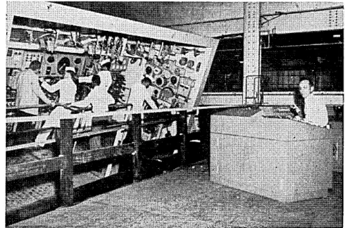
Figure 1 shows the complete system. The equipment contained in the five relay racks on the left comprises the input system, while that contained in the five racks on the right comprises the digital system. The center rack contains terminal strips for connecting the two.
Figure 2 is a block diagram of the input system. Several types of transducers are used, all of which have output signals in the 0-20 mv range to feed directly into the data processing system without prior amplification.
This particular version of M adis I monitors and reo cords the outputs of 576 thermocouples. Each thermo-couple is connected to a reference j unction maintained at 2500
F. constant temperature for maximum stability. When the temperature of the parameter being measured requires a different base reference, this reference is estab-lished by voltage-biasing circuits on the output side of the reference junction.
When other than standard ranges are required, potentiometer gain circuits in conjunction with the bias circuits extend the range to that necessary to monitor a particular parameter. Each bias and gain module con-trols 72 data channels.
Provision is made on the temperature monitor unit
for monitoring bias voltage at each of the eight bi'as and gain modules. Provision is also made for monitoring reference junction heater temperature.
A number of dc strain gage type transducers with output voltages in the same 0-20 mv range are used to provide pressure data. Later ~his pressure data can be correlated with temperature and flow data to give a com-plete picture of the process or operation monitored.
Mass flowmeters or volumetric flowmeters of the Waugh type give continuous flow indications on the function measured. Some ac and dc voltage measure-ments are also made. AC signals must, of course, be rectified and attenuated to bring the values down to the required 0-20 mv range. DC signals go through a voltage divider network to provide necessary .attenuation.
Each of the signal outputs are brought' to a three-terminal output connection in the three-terminal rack. Here is where connections between the input system and the output system are made. Any input signal can be routed in such a manner that the output signal will appear as a specific output sample of the commutated information, i.e., input signal no. 17 can be made to appear as output sample no. 435 or any other number.
The digital system (see Figure 3) consists of a com-mutator that can be operated in a manual or automatic mode, a control and timing unit, an elapsed-time generator, analog-to-digital converter, remote data code indicators, digital storage register, digital magnetic tape recorder, and a system monitor.
[image:18.612.46.558.550.749.2]The heart of the Madis I digital system is the com· mutator which is basically a relay matrix driven by a ring counter. It contains a total of 675 relays that operate sequentially at a rate of 125 per second. The modular concept employed throughout the system pro-vides for addition or subtraction of relays in multiples of 25. Where higher sampling rates are desired, the relay
Figure 1. Complete Madis I data processing system.
,,,itching rate Illay he increa~ed to gOO per ~e(,ol1d.
Circuitry developed ill conjunction with the ('Olll' llIutator permit~ direct comlllutation of de signal~ at the
1.,\,(') of 1l-20 111\'. \\'ith an over-all :'itated sv~tem error of )e!':'~ than 0.15(;; and, at the same time, give~ good ('(Jlnmon nlOde rejection. Commutation of millivolt sig-nals ill the prt~s(,llce of SO \'oit rms COlllnlun mod!' yolt-ages is possihle. COllllllOIl Illode rejection of dc_ 6() cps. and 40() cps voltages i~ es~(~ntially infinit('. III addition_ a
10\\ -pass filter is also used at the COl1lnlutator input to
t'limi-nate unwanted vo\tagt's generated hy power or s\\itchillg frequencies.
COllllllutator s\\'ilching synchronizatioll. as well as synchronizatioll of all components of the system. is oh-tained frolll the control and timer unit.
Elapsed-time indications are generated at the
Iwgin-Fin. 2. Block cliagmm of inpHt system.
TI-I ERMOCOUPLes
<
PRESSURE TRANSDUCE~
A. C. VOL.TA6E5
D.C. VOLTAGES
MISC.
0-20 MV
~IGNAL.l5
...
"-€
-~
0
THERIo.10c00PLt:
HOT REFEReNCE JUNCTIONS
SUi CHANNELS
I
PRE.5!5URf! TRANSDUCER .JUNCTION BOX
I •
WAUGH FLOW
CONveRTeRS
A.C. VOLTAGE CONVERTf.R
D.C. VOLTAGI!
I
CONVl!:RTl!:R
/ling of each ('onllllutatioll ('\ (,1(, and ar(' gi\('n in hours.
Illillllt('S. and t(,nths of Illi/lul<'~. Tilll<' ('ol')'('lalio/l t() a
Illilli~e('ol)(1 can
IH-'
prmid('d "h('['(' the tran~i('nt natul'l' of the data rt'quires Illore ac('urate tilll!' indications.Three channels of information are available for in-st'rtion of sllch fiXt~d parameters a~ test numhers. Tillle insertioll into the s~~tern is controlled hy th(' rda\" Illatrix in sllch a IlUlllller that the sit!nal does not ella;l!!!' dur-ing its sampldur-ing period. Time is illserted at th(' begin-ning of a sampling cycle. and evcnt time for a particular channd function is then calculated frolll tilt' ori!!inal timt' a1ld the known switching rate.
The remolf' data code indicator sho\\s in hincH\' form the output of the analog-to-digital C()ll\'(~rt('r.
t\
relllolt' data code indicator is located wherever trans-dW'('r out put scali ng is required. The data code i1ldi· cator is used with comlllutator operation in the Illallual positioll to permit monitoring of any selected channel. Analog-tn-digital eonH>rsioll is accomplished by an r---PIlEU510N f -POWER ~PPLYTeRMINAl. THERMOC:OUPL.E fo-r - RAGK 61A5 ANO GAIN
UNITS
ntAPf:AATURr
L 5Y!sT~
1040N I TOR
j
PRECISION poweR
SUPPLY
i
,
I
I
A DATA PROCESSING SYSTEM . . .
MANUAL COMMUTATOR CONTROL
G7S eN.
LOWL
[image:20.612.47.553.130.428.2]GOMMl/
Figure 3. Block diagram
of
digital system.Epsco Datrac Model B high-speed converter. This con-verter consists of a high-speed digital-to-voltage conver-ter, a high-speed low-level digital voltage comparator, a digital storage register, and a programmer. When the converter is used as a voltage-to-digital translator, the digital-to-voltage converter is employed as part of a closed-loop nulling system.
Operation is based on a programmed successive ap-proximation technique. During the voltage-to-digital encoding process, a rapid series of decisions is made, controlled by a comparison of the input voltage and the voltage generated internally by the digital-to-voltage con-verter. Each binary decision is completed within two microseconds with a stated accuracy of 0.05%.
This high digitizing rate produces excellent signal-to-noise ratios during conversion. The output code is an II-bit straight binary signal which goes to the digital storage register and to the remote data code indicator. The storage register unit provides digit storage of the II-bit code and the correct output density for re-cording on the magnetic tape of the recorder. This, of course, is necessitated by the compatibility requirements of the computer input. Parity marks for the tape are also provided by the storage register.
This controlled recording density, together with the
18
insertion of required gaps and parity marks, assure com-plete compatibility to the computer input requirements. No additional processing is necessary prior to feeding the computer; however, outputs for punched card data can be supplied for card input computers or X-Y plot-ters or other special equipment.
Magnetic tape recording and playback equipment utilizes an Ampex FR-207. IBM hubs and reels are sup-plied to simplify still further data input requirements of IBM computers. The IBM 704 reduces the data by performing, scaling, linearizing, and arithmetic functions on each data point in a fraction of the time required for recording. Final data is presented on tabulated sheets. Another feature of
Madis I
is the system monitor by which system operation can be monitored at almost any step in the processing. Com~uato: outpu~ wave-forms, timing pulses, storage regIster mformatIon, or tape monitoring can be presented visually.Accessory equipment can be used to adapt the
M adis I
to almost any data processing application. These accessories may include stich features as special record-ers, mobile input adapter carts for transdu~ers an~ as-sociated conditioning equipment, automatIc b rId g e balancing, remote reference junction and bias units, ~pe~ ial precision power supplies, or remote read-out mdI-cators. Channels may vary from 100 to more than 1000, with sampling rates up to 800 per second.Circle 104 on Reader Service Card