(
DSD 7215
MULTIBUSe DISK CONTROLLER
Copyright © 1983
USER GUIDE
Data Systems Design, Inc. 2241 Lundy Avenue
San Jose, CA 95131
All rights reserved. No part of this manual may be reproduced in any form or by any means without prior written permission of Data Systems Design, Inc.
Data Systems Part No: 040038-01 Revision A
('
(
WARRANTY STATEMENT
Data Systems Design's products are warranted against defects in materials and workmanship. For DSD products sold in the U.S.A., this warranty applies for ninety (90) days from date of shipment.
*
DSD will, at its option, repair or replace either equipment or components which prove to be defective duri~ the warranty period. This warranty includes labor, parts, and surface travel costs of system modules or components. Freight charges for other than surface travel or for complete systems returned for repair are not included in this warranty. Equipment returned to DSD for repair must be shipped freight prepaid and accompanied by a Material Return Authorization number issued by DSD Customer Service. Repairs necessitated by shipping damage, misuse of the equipment, or by hardware, software, or interfaci~ not provided by DSD are not covered by this warranty •. NO OTHER WARRANTY IS EXPRESSED OR IMPLIED, INCLUDING, BUT NOT LIMITED TO, THE IMPLIED WARRANTIES OF MERCHANTABILITY AND FITNESS FOR A PARTICULAR PURPOSE. DSD SHALL NOT BE LIABLE FOR CONSEQUENTIAL DAMAGES.
ORDERS SHOULD BE PLACED THROUGH THE NEAREST REGIONAL SALES OFFICE.
WESTERN REGION SALES Data Systems Design, Inc. 2580 Mission College Blvd. . Suite 108
Santa Clara, CA 95050 (408) 727-3183
EASTERN REGION SALES Data Systems Design, Inc. 51 Morgan Drive
Norwood, MA 02082 (817) 789-7820
~: 710-338-0120
CENTRAL REGION SALES Data Systems Design, Inc. 5050 Quorum Drive
Suite 339
Dallas,TX 75240 (214) 980-4884
CORPORATE HEADQUARTERS Data Systems Design, Inc.
2241 Lundy Avenue San Jose, CA 95131
(
PRBFACB
Thm manual describes the features, specifications, and programming of the DSD 7215 Multibus Dmk Controller. Instructions for equipment installation, operation, and elementary troubleshooting are included.
The material in this manual is subject to change without notice. The manufacturer assumes no responsibility. for any errors which may appear.
Please note that Intel, iSBC, iSBX, Multibus and the combination of iSBC, iSBX, or RMX and a numerical suffix are registered trademarks of Intel Corporation. CP/M is a trademark of Digital Research, Inc. UNIX is a trademark of Bell Laboratories.
TABLE OF CONTENTS
(
1.0 GENERAL INFORMATION 1-11.1 Introduction 1-1
1.2 Features 1-1
1.3 Self-Test and Diagnostics 1-1
1.4 Off-Line Backup Capability 1-1
1.5 Summary 1-2
2.0 SPECIFICATIONS 2-1
2.1 Introduction 2-1
2.2 Data Storage Capacities 2-1
2.3 Media Recommendation 2-3
2.4 Cables and Connectors 2-3
2.S Specifications 2-8
3.0 INSTALLATION 3-1
3.1 Introduction 3-1
3.2 Unpacking and Inspection 3-1
3.3 Installation 3-1
3.4 Jumper Options 3-1
3.4.1 Jumper Configurations 3-1
3.4.2 Bus Arbitration Modes 3-5
3.4.3 Source V oltage Selection for -S V de Output 3-S
3.4.4 Drive Jumpering 3-5
3.S Initial Checkout and Acceptance Tests 3-6
3.5.1 Test and Verification 3-6
(
4.0 PROGRAMMING 4-14.1 Introduction 4-1
4.2 Winchester Disk Organization 4-1
4.3 Floppy Disk Organization 4-1
4.4 Streaming Tape Organization 4-1
4.5 Host/Controller Communications 4-2
4.5.1 Input/Output Commands 4-2
4.5.2 Interr~ts 4-3
4.5.3 Memory-Based Control Paths 4-3
4.5.4 Address Representation 4-3
4.5.5 Wake-Up Block (WUB) 4-5
4.5.6 Channel Control Block (CCB) 4-5
4.5.7 Controller Invocation Block (CIB) 4-6
4.5.8 Input Output Parameter Block (IOPB) 4-7
4.6 Issuing Commands and Receiving Status 4-9
4.7 Controller Commaoos 4-10
4.7.1 Initialize (OOH) 4-11
4.7.2 Transfer Status (OlH) 4-15
4.7.2.1 Error Status Buffer 4-15
4.7.2.2 Extended Error Status 4-17
4.7.3 Format (02H) 4-17
4.7.4 Read Sector ID (03H) 4-19
4.7.5 Read Data (04H) 4-19
4.7.6 Read Buffer and Verify (05H) 4-21
(/
(
TABLE OF CONTENTS (Cont)
4.7.9 Initiate Track Seek (08H) 4.7.10 Buffer I/O (OEH)
4.7.11 Diagnostics (OFH) 4.7.l2 Reset Tape Drive (80H) 4.7.13 Disk Image Backup (81H) 4.7.14 Disk Image Restore (82H) 4.7.15 Read Tape Status (83H) 4.7.16 Tape Retension Cycle (84H) 4..8 Error Processing
4.8.1 Bad Track Handling 5.0 CONTROLLER ARCHITECTURE
5.1 DSD Controller Description 6.0 USER LEVEL MAINTENANCE
6.1 Introduction
6.2 Troubleshooting and Fault Analysis 6.3 Off-Line HyperDiagnostics
6.3.1 HyperDiagnostics and Error Code Interpretation 6.4 Maintenance Assistance
APPENDICES Appendix A - Drive Jumpering Tables
Appendix B - Cross Reference Index
Table 2-1 2-2 2-3 2-4 2-5 2-6 3-1 3-2 3-3 3-4 4-1 4-2 4-3 4-4 4-5 4-6 6-1 TABLES Title
-Winchester Drive Data Organization and Capacity Floppy Drive Data Organization and Capacity
Quarter-Inch Streaming Tape Drive Data Organization and Capacity Multibus PI Connector Pin Assignment
Controller/Multibus Signals Specific a tions
Jumper Configurations
W7 and W9 Jumper Configurations W6 Jumper Configurations
Indicator Sequence Addressing
Byte Values Example (IOPB) Error Status Buffer
Error Status Bit Definition Extended Error Status Codes On-Line Diagnostics
Off-Line Hyper Diagnostics and Jumper W6 Configuration
TABLE OF CONTENTS (Cont)
(
FIGURESFigure
!!!!!
I-I DSD 7215 Multibus Controller Board vi
2-1 Cable and Connector Configuration 2-3
2-2 Master Command Access Timing 2-6
3-1 Jumper Locations 3-2
3-2 Source Select for -5 Vdc 3-5
4-1 Winchester Disk Organization 4-1
4-2 Winchester Sector Data Format 4-2
4-3 Chain of Communication Blocks 4-4
4-4 Wake-Up Siock 4-5
4-5 Channel Control Block 4-6
4-6 Controller Invocation Block 4-6
4-7 Input Output Parameter Block 4-9
4-8 lOPS initialize Function 4-12
4-9 lOPS Initialization Examples 4-13
4-10 lOPS Transfer Status Function 4-15
4-11 lOPS Format function 4-18
4-12 10PB Read Sector ID Function 4-19
4-13 lOPS Read Data Function 4-20
4-14 lOPS Read Buffer and Verity function 4-21
4-15 lOPS Write Data function 4-22
4-16 10PB Write Buffer Data Function 4-23
('
4-17 10PB Initiate Track Seek function 4-244-18 10PB Suffer I/O Function 4-25
4-19 lOPS Diagnostic Function 4-26
4-20 10PB Reset Tape Drive Function 4-28
4-21 lOPS Disk Image Backup Function 4-29
4-22 lOPS Disk Image Restore Function 4-30
4-23 10PB Read Tape Status function 4-31
4-24 lOPS Tape Retension Cycle Function 4-33
5-1 DSD 7215 Multlbus Controller Block Diagram 5-2
6-1 Timing for CRI, CR2 BUnking Wakeup Addr_ Test 6-3
6-2 CRI Blinking Error Code 6-5
(
Figure 1-1 •. DSD 7215 Multibus Controller Board
(.
)
1.0 GENERAL INFORMATION
(~
1.1 Introduction(
The DSD 7215 Multibus Disk Controller is a compact single-board controller for Winchester, floppy, and streaming tape drives that will interface with any Multibus compatible computer system. The DSD 7215 emulates the Intel iSBC 215 and iSBX 218 controller combination, and operation is compatible with software and operating systems supporting that product.
DSD 770 is a generic name for a class of rack mounted systems. Any comments relating to DSD 770 Series disk systems would also apply to user configured systems of a similar type.
This manual provides user information for the OSD 7215 controller. Coverage includes features, specifications, installation, operation, programming, block diagram and architecture, and user level maintenance.
1.2 Features
Features of the OSD 7215 Controller are:
• Standard interfaces for Winchester, floppy, and streaming tape drives.
• All drives are connected pin-for-pin by flat ribbon cables for easier installation. • All interfaces plus data separation are on a single Multibus card for best system cost. • Buffering provided for non-interleaved operation and off-line disk-to-tape backup
operations.
• Built in high reliability and data integrity.
• Meets the requirements of the IEEE-P796 specifications for the Mul~ibus standard, including 24-bit addressing.
• Emulates Intel's iSBC 215 and iSBX 218 controller combination.
• Compatible with operating systems supported by Intel, such as RMX-86.
1.3 Self-Test and Diagnostics
Two LEOs, labelled CRI (ERR) and CR2 (RDY) are mounted on the controller card. These LEDs respond according to the option setting and error condition. LED CR2 (ROY) indicates whether the controller is ready to accept a new command (ON) or is busy (OFF). LED CRI (ERR) is active when an error is detected. Use of these indicators during initial checkout and acceptance testing is detailed in Section 3.
Resident PROM diagnostics (jumper selectable by user) may be used for fault isolation to determine if a problem involves the controller hardware, disk drives, or bus. Refer to Section 6 for detailed fault isolation procedures.
1.4 Off-Line Backup Capability
(
1.5 Summary
Disk memory systems combining Winchester, floppy, and tape drives are opening new application possibilities for small computer systems. Their functional design and performance rival that of large disk systems costing several times as much. When considering a Winchester based disk memory system, the user should look beyond the usual considerations of capacity and backup and examine the function and capability of the entire system.
Data Systems Design has been an industry leader in the design and manufacture of disk storage systems since 1975. The DSD Multibus Controller is a powerful and effective design offering a combination of price, features, and ~rformance unavailable from any other source. These features are summarized below:
Compatible:
• Multibus compatible board format
• Emulates the iSBC 215 and iSBX 218 combination
• IBM standard formats for disks (single- and double-density) • Standard drive interfaces
• IEEE-P796 standard bus, including 24~it addressing Flexible:
• Supports floppy, tape, and Winchester • Variety of standard drive selection • Up to two disk drives of each type
• Eight- or 16~it I/O address for 8- or I~it systems • Several bus arbitration choices
• Variable disk interleave • Four sector sizes
Powerful:
• Non-interleaved disk transfer (floppy and rigid)
• Byte or word transfers .
• Burst mode transfer of any length (multiple sector transfers, up to entire disk) • Overlapped seeks
• Five megabytes per minute disk backup without computer intervention • Efficient bus arbitration
• Wide bandwidth design • Memory based commands Easy to Integrate:
• Singl~d, occupies one slot • One-to-one cable connection • Easy jumper configuration • Flexible -5 Vdc source selection • Standard software interface
• Complete systems available, rack mount or table top • Clear, complete, professional documentation
C
J
Cost Effective:
• Three controllers in one • No extra boards to buy • Integrated data separator
• Uses lower cost Shugart and Quantum drives Reliable:
• Effective media flaw management • Thorough test and burn-in
• Power up self-test
• Wide margin phase-locked-loop
• Full sector buffering eliminates data overrun and potential for lost data
• ECC for Winchester disk, 32-bit detect, ll-bit correct. Automatic error recovery and retry. Transparent data error correction
• Full disk backup
• Bus time-out eliminates hang-up states • Conservative, no compromise deSign Serviceable:
• Flashing error codes for easy problem identification • On-board diagnostics for fault isolation
• HyperServiceTlllwith Rapid Module ExchangeT•
2.0 SPECIFICATIONS
( 2.1 Introduction
(
{
This section contairs controller specifications, dimensions, and environmental and power requirements. Specificatiors include data storage capacities, recording characteristics, and data transfer for eight-inch Winchester and floppy drives. Requirements include those for interface cabling and connectors.
2.2 Data Storage Capacities
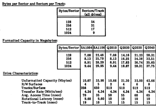
Tables 2-1 through 2-3 provide data organization information and capacities for the eight-inch Winchester, floppy and quarter-inch streaming tape drives.
[image:11.615.38.553.359.708.2]The Winchester drives operate with all standard iSBC 215 sector sizes. These include the 128, 256, 512, and 1024 bytes per sector formats. The floppy disks handle IBM standard formats such as, IBM si~le-density (128 to 1024 bytes per sector) and IBM double-density (256 to 1024 byes per sector), including double-sided. This nexibility enables the user to copy programs from one format to another using the Winchester as intermediate storage.
Table 2-1. Winchester Drive Data Organization and Capacity
Bytes per Sector and Sectors per Track:
Bytes/Sector
128 256 512 1024 Formatted Capacity in Megabytes:
Bytes/Sector 128 256 512 1024 Drive Characteristics:
Unformatted Capacity (Mbytes)
ec) R/W Surfaces
Tracks/Surface
Transfer Rate (Mbits/s A vg. Access Time (ms Rotational Latency (m Track-to-Track (msec
ec) sec)
)
Sectors/Track (all drives)
54 31 17 9
SA1004 SAll06 1.08 22.46 8.13 25.79 8.91 28.29 9.44 29.95
10.67 33.90
4 5
256 650 4.34 4.34
10 35
9.60 9.60 19 10
2-1
Q2010 Q2020 7.08 14.16 8.13 16.25 8.91 11.83 9.44 18.87
10.66 21.30
2 4
512 512 4.34 4.34 50 55 10 10 15 15
Q2030 Q2040 21.23 28.31 24.38 32.51 26.74 35.65 28.31 37.15
32.00 42.66
6 8
Table 2-2. Floppy Drive Data Organization and Capacity Bytes per Sector and Sectors per Track:
Sectors/Track
Bytes/Sector Single-Density Double-Density
128 26
-256 15 26
512 8 15
1024 4 8
Formatted Disk Capacity per Drive:
Formatted Capacity in Kbytes
Single-Sided Double-Sided
Bytes/Sector Single-Density Double-Density SinKle-Densi~ Double-Density
128 256
-
512-256 296 512 591 1.025
512 315 591 630 1.182
1024 315 630 630 1.26
. Drive Characteristics:
Single-Sided Double-Sided
( Unformatted Capacity (Kbytes)
Surfaces
Tracks/Surface
Transfer Rate (Kbits/sec) Rotational Latency (msec)
Single-Density 401
1 77 250 83
Double-Density 802
1 77 500 83
Single-Density Double-Density
802 1.604
2 2
77 77
250 500
83 83
Table 2-3. Quarter-Inch Streaming Tape Drive Data Organization and Capacity Capacity:
Unformatted Formatted Recording Characteristics:
Media:
Tracks Form Code
Head Format Density Transfer Rate
21.6 Mbytes - Four Tracks 20 Mbytes - Four Tracks
Four Serpentine
Run length limited
Read while write with separate erase 8000 bpi
90 Kbytes per second
(.
Table 2-3. Quarter-Inch Streamirw Tape Drive Data Organization and Capacity (Cont) Format:
528.5 bytes per block arranged into five fields:
Gap 13 Bytes
Sync Mark .5 Bytes
User Data 512 Bytes
Block Address 1 Byte
CRC 2 Bytes
Format is illustrated below (read right to left):
CRe ADDRESS 512 BYTE SYNC GAP
CAe ADDRESS DATA FIELD SYNC GAP =2 -1 BYTE DATA FIELD =.5 =13BYTES
BYTES BYTES
2.3 Media Recommendation
Dysan or Maxell fioppy disks and 3M quad-density, DC300XL or DC300XL Plus, 450-foot length, tape cartridges are recommended. Do not use DC 300 tape cartridges.
2.4 Cables and Connectors
F.1gure 2-1 shows typical connector and cabling requirements. The connectors (wired pin-to-pin) used with Jl through J4 are female connectors with 1/l0-ineb pin spacing.
TERMINATOR INSTALLED CABLE AND CONNECTOR REQUIREMENTS
P1: 88-PlN MULTISUSCONNECTOR
P2: eo -PIN OPTIONAL MULTI BUS SIGNALS r PIN 57: ADR1~ (HEX) PIN 55: ADR181 (HEX) 2Q.PIN WINCHESTER DATA PIN 58: ADR151 (HEX) PIN 58: ADR171 (HEX)
L
J1: 50- PIN TAPE DRIVE CONNECTOR CABLE IS 32 FEET (10 METERS) MAXIMUM. J2: 50 - PIN DRIVE CONTROL CONNECTOR
CABLE IS 10 FEET (3 METERS) MAXIMUM. r
J3: 20 - PIN WINCHESTER DATA CONNECTOR 2Q.PlN WINCHESTER DATA CABLE IS 20 FEET (8 METERS) MAXIMUM •
L
.14: 20-PIN WINCHESTER DATA CONNECTOR CABLE IS 20 FEET (8 METERS) MAXIMUM.
J3 AND .14 ARE INTERCHANGEABLE.
1
STREAMING TAPE
II
5O-PIN CABLEDRIVE ~~~---~
-
5IJ.PIN DRIVE CONTROl CABLE-]...
~J1 .. J2 ... J3 J4 ~
0607215 MULTISUS CONTROLLER
P1 P2
Figure 2-1. Cable and Connector Configuration
2-3
a
EIGHT-INCH WINCHESTER DRIVE
EIGHT·INCH WINCHESTER DRIVE
EIGHT·INCH FLOPPY DRIVE
EIGHT·INCH FLOPPY DRIVE
(
The controller communicates with the CPU via the Multibus interface. Table 2-4 lists the Multibus connector pin assignments. Table 2-5 describes the controller/Multibus interface signals. Figure 2-2 is a diagram of the controller/Multibus interface timing signals with timing requirements. The controller is connected to the Multibus interface through connector Pl, an S6-pin, double-sided, printed circuit edge connector. Connector P2 provides for optional Multibus signals, listed in Figure 2-1.
Table 2-4. Multibus Pl Connector Pin Assignment
PI (Component Side) PI (Cireuit Side)
Pin Mnemonic* Description Pin Mnemonic* Description
1 GND Signal GND 2 GND Signal GND
3 +5V +5 Vde 4 +5V +S Vde
Power 5 +5V +5 Vde 6 +5V +5 Vdo
SuppUes '1 +12V +12 Vde 8 +12V +12 Vde
9 -SV -SVde 10 -SV -SVdc
11 GND Signal GND 12 GND Signal GND
13 BCLK/ Bus Clock 14 INIT/ Initialize
15 BPRN/ Bus Priority In 16 BPRO/ Bus Priority Out
Bus 1'1 BUSY/ Bus Busy 18 BREQ/ Bus Request
Controls 19 MRDC/ Memory Read Command 20 MWfC/ Memory Write Command
21 IORC/ Not Used 22 10WC/ I/O Write Command
23 XACK! XFBR Acknowledge 24 INHl/ Not Used
Bus 25 Reserved 26 INH2/ Not Used
Controls 27 BHEN/ Byte High Enable 28 ADR10/
and 29 CBRQ/ Common Bus Request 30 ADRll/ Address
Addresl 31 CCLK! Not Used 32 ADRI2/ Bus
34 ADR13 33 INTAI Not Used
35 INT6/ 36 INT'l/
Interr~ts 37 INT4 Parallel 38 INTS/ Parallel
39 INT2/ Interrupt 40 INT31 Interrupt
41 INTO/ Requests 42 INTlI Requests
43 ADRE/ 44 ADRFI
45 ADRCI 46 ADRD/
47 ADRA/ 48 ADRB/
Address 49 ADR81 Address 50 ADR9/ Address
51 ADM/ Bus 52 ADR71 Bus
53 ADR4/ 54 ADR51
55 ADR2/ 56 ADR3/
57 ADROI 58 ADR11
59 DATEI 60 DATFI
61 DATC/ S2 DATDI
63 DATAl 64 DATB/
Data 65 DAT81 Data 66 DAT9! Data
67 DATS! Bus 68 DAT'l1 Bus
69 DAT4! 70 DAT5!
71 DAT21 72 DAT3!
73 DATOI 74 DATl/
75 GND Signal GND 7& GND Signal GND
77 Reserved 78 ReserVed
Power 79 -12V -12 Vdc 80 -12V -12 Vdc
SuppUes 81 +5V +5 Vdc 82 +5V +5 Vdc
83 +5V +5 Vdc 84 +5V +12 Vdc
85 GND Signal GND 86 GND Signal GND
• "I" following the signal name indicates an active low.
(
(
'-'
Signal
ADRO/, ADRP/ ADRIO/-ADRI3/
BCLK/
BHEN/
BPRN/
BPRO/
BREQ/
BUSY/
CBRQ/
DATO/-DATP/
INrr/
INTO/-INT7/
10WC/
MRDC/
Table 2-5. Controller/Multibus Signals Punctional Description
Address. These 20 lines transmit the address of the memory location or I/O port to be accessed. For memory access, ADRO/ (when active) enables the even byte bank (DATO/-DAT7/) on the Multibus connector; i.e., ADRO/ is active for all even addresses. ADR13/ is the most significant address bit.
Bus clock. Used to 'synchronize the bus contention logic on all bus masters.
Byte High Enable. When active low, enables the odd byte bank (DATS/-DATF/) onto the Multibus connector.
Bus Priority In. When low, indicates to a particular bus master that no higher priority bus master iJ requesting use of the bus. BPRN/ is synchronized with BCLK/.
Bus Priority Out. In serial '(daisy chain) priority resolution schemes,
BPROI
must be connected to the BPRNI input of the bus master with the next lower bus priority.Bus Request. In parallel priority resolution schemes, BREQ/ indicates that a particular bus master requires control of the bus for one or more data transfers. BREQ/ is synchronized with BCLK/.
Bus Busy. Indicates that the bus is in use and prevents all other bus masters from pini. control of the bus. BUSY! is synchronized with BCLK/.
Common Bus Request. Indicates that a bus master wishes control of the bus but does not presently have control. As soon as control of the bus is obtained, the requesting bus controller raises the CBRQ/ signal. Data. These 16 bidirectional data lines transmit and receive data to and from the addressed memory location or I/O port. DATF I is the most significant bit. Por data byte operations, DATO/-DAT7 is the even byte and DATS-DATP! is the odd byte.
Initialize. Reset the entire system to a known internal state.
Interr~t Request. These eight lines transmit interrupt requests to the
appropriate interrupt handler. INTO/ has the highest priority.
I/O Write Command. Indicates that the address of an I/O port is on the Multibus connector address lines and that the contents on the Multibus connector data lines are to be accepted by the addressed port.
Memory Read Command. Indicates that the address of a memory location
is
on the MUltibus connector address lines and that the contents of the location are to be read (placed) on the MultiblB connector data lines.Signal
( MWrC/
XACK!
BUSYI
ADDRESS
WRITE
DATA
READ
('- DATA
COMMAND
(MRDCI
ORMWTQ)
XACKI
va
ADDRESS
Table 2-5. Controller/Multibus Signals (Cont) Functional Description
Memory Write Command. Indicates that the address of a memory location is on the Multibus connector address lines and that the contents on the Multibus connector data lines are to be written into that location.
Transfer Acknowledge. Indicates that the address memory location has completed the specified read or write operation. That is, data has been placed onto or accepted from the Multibus connector data lines.
MASTER COMMAND ACCESS TIMING
~ BUS ACCESS BUS RELEASE
Y
~tDB:i
_ _ _ _ _
_
---'~
.. i .. ---
ADoREllS ST'''''I-
IAH~""---¥
~T.STA....
r-'o~
~"---)f
DATA STABLE~
----~~~~~--~
~,~tDH~R~
____ __
"---=1
_ _ _ _ _ --.:...-+t t_OSX
t~KOO
/ _
-SLAVE COMMAND TIMING
~It'---
ADDRESS STABLE - - - -...C
...
~~
~~~
~~~M
---"")f
.. ---
DATA STABLE---I~
....
,...;..--SYSTEM CPU
::t
;sos
r-
t;
tSDHW~
•=,No
r""' .. ---
lACC---~~t
:{
~
L
\ ____
.-f--XACKI
BUS EXCHANGE TIMING
r-
tBCY
~
tBL1;: tBH:j
~t_~--\
I
\
J " __
-.-II
- - - - ,
\
__________
~I.
____
m_A_rr~~DB_~_~
________________ __BCLKI
BREGV
BPRNI
---f
tOBYFI;::
----I
tOBYr-_____________________ ,..,F
HIGHZ~'-
_ _ _ _BUSYI
BPROI
/+-tOBPO::j
\ _
-Time in Nanoseconds
Parameter Minimum Maximum Description
tDB 61 Busy-to-address/ data delay
tSc
60 Address/ data set-up to com mandtXKCO 500 XACK/ to command turn off '
tAR 50 Address hold time
tDHW 50 Data hold time
tDRR 0 Read data hold time
tDSX 0 Data set-up time before XACK/
tSAS 23 Address set-up time to I/O command
tSDS 32 Data set-up time to I/O command
tSAR 36 Address hold time from I/O command
tSDHW 50 Data hold time from I/O command
tACC 77 I/O access time
tX.KO 10 63 XACK/ hold time from I/O command
tBCY 100 Bus clock cycle time
tBL 35 65 Bus clock low
tBR 35 65 Bus clock high
tDRQ 32 Bus request delay
tDBY 48 Bus busy turn on delay
tDBYF 65 Bus busy turn off delay
tDBPN 0 Priority input set-up time
tDBPO 7 BPRO/ serial delay from DPRN/
tWAfr co Requesting master bus access time
TP 253182
Figure 2-2. Master Command Access Timing (Cont)
(
(
2.S Specifications
Table 2-6 provides the power, physical, and environmental specifications for the controller.
• Physical Specifications Mounti~:
Dimensions:
• Power Requirements
•
Environmental ~ecifications Operating Temperature: Humidity:Cooling:
•
Throughe!:!t SpeCifications Sector Averages: ReadWrite Track Average:
Non-interleaved Cylinder Average:
Non-interleaved Disk Average:
Non-interleaved Eight tracks/cylinder
Table 2-6. Specifications
Occupies one card slot in Multibus backplane .06" Thick x 12.0" Long x 7.1" Wide
(l.5 cm Thick x 30.5 cm Long x 18.0 cm Wide)
+5 V dc, S% @. 5.1 amps typical -5 V dc, 5% @ .08 amps typical +12V dc, 5% @. .1 amps typical Note
Jumpers allow Multibus -12V or -10V to be used as source voltage for -5 V requirement.
410 F to 1310 F (SO C to 550 C) Up to 90% non-condensing
DSD 7215 controller board dissipates 24W
ot
heat (80 BTU/hr). Adequate air circulation must be, maintained to prevent a temperature rise above 1310F (550C).1.24 }./Sec plus memory read access time/word minimum
1.46 llSec plus memory write access time/word minimum
480 Kbytes/sec maximum
480 Kbytes/sec maximum 1024 bytes/ sector Q2000
410 Kbytes/sec maximum
3.0 INSTALLATION
( 3.1 Introduction
(
This section contains information on unpacking, inspection, configuration, and initial checkout of the DSD Multibus Disk Controller.
3.2 Unpacking and Inspection
When the DSD Controller arrives, inspect the shipping container immediately for evidence of mishandling during transit. If the container is damaged, request that the carrier's agent be present when the package is opened. Compare the packing list attached to the shipping container against your purchase order to verify the shipment is correct.
Unpack the shipping container and inspect each item for external damage such as broken controls and connectors, or scratches and loose components. If damage is evident, notify DSD Customer Service immediately.
Retain the shipping container and packing materials for examination in the settlement of claims, or for future use.
3.3 Installation
The controller board may be installed in any Multibus-compatible backplane that meets the power and cooling requirements specified in Section 2.
Up to two floppies and two Winchesters may be connected to the con~roller (See Figure 2-1). The last drive in the chain must be a Winchester drive with terminating resistors connected. Ensure the floppy write data line is properly terminated on that Winche~ter.
3.4 Jumper Options
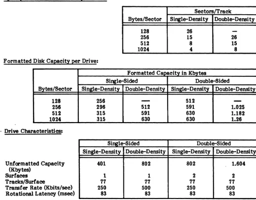
Jumper options allow the user to tailor the installation to the requirements of his particular system. Figure 3-1 shows jumper locations and pin configuration of each jumper on the controller board.
Normally, jumper options are exercised by placing a Berg Stik mini-jumper on the indicated pins. The exception to this is jumper WIO. It is wire-wrapped at the factory because the physical layout of the pins precludes the use of the mini-jumpers.
3.4.1 Jumper Configurations
Tables 3-1 and 3-2 summarize the DSD Controller jumper configuration installed at the factory. Table 3-1 covers all board jumpers except W6, W7, and W9. These jumpers are of slightly different configuration and are described in Tables 3-2 and 3-3. Jumpers W2, W4, and Wl3 are for factory use only, and should not be changed in the field. User should note that there is no jumper labelled WI on the board.
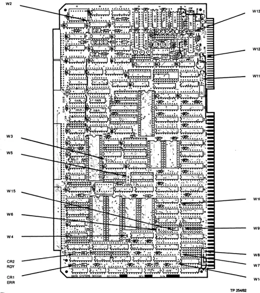
Jumper groups W7 and W9 (Table 3-2) form the wake-up address (WUA) jumper setting that is multiplied by 16 (shifted left 4 bits) to obtain the 20-bit Multibus address of the wake-up block. W9 contains the low order bits (0 to 7) and W7 the high order bits (8 to 15) of . the WUA jumper setting. These bits are set at the factory for OF70 hex. For the WUA only,
the selected address, set by jumpers, must be a mUltiple of 16.
(0
Jumper W6 provides options for the selection of types of drives supported by the controller (See Table 3-3). It is also used to select off-line diagnostic testing. Refer to Section 6 for
usirv
W6 Jumper group with off-line HyperDiagnosticsJMW2
W3
W5
W15
we
W4
CR2 ROY
[image:20.620.22.545.111.700.2]CR1 ERR
Figure 3-1. Jumper Locations
W13
W12
W11
W10
W9
we
W7
W14
TP254182
~
~ ~Table 3-1. Jumper Configurations
Jumper Function Pins F actary Setting Options Remarks
IN OUT
W2 Factory Use Only 1-2 X None. Leave as set.
W3 Byte- or Word-Size 1-2 X Byte-size data bus selected. User option.
Data Transfers IN selects 16-blt data bus.
W4 Factory Use Only 1-2 X
! 3-4 X None. Leave as set.
I
1-2 X Yield to higher priority mode. User option. Except for over- I
Bus Arbitration 2-3 X IN
=
yield to any request mode. ride mode, only one jumper at IW5 !
Mode Select 2-4 X IN
=
single-transfer mode. a time is IN. See paragraph 5-6 X 1-2 and 5-6 IN=
override mode. 3.4.2.W8 Serial or Parallel Bus 1-2 X Serial bus priority scheme selected. User option. Priority Continuity OUT
=
parallel bus pric;rity scheme.w
~ C-o X Priority level 0 (Highest)
C-l X Priori ty level I
C-2 X Priority level 2 User option. Factory set level 5.
WIO Interrupt Priority C-3 X Priority level 3 Factory wire-wrapped. User may
Level Select C-4 X Priority level 4 change as required.
C-5 X Priority level 5 (Factory Set)
C-6 X Priority level 6 .
C-'1 X Priority level '1 (Lowest)
Wll -5 V dc Source 1-2 X -12 V dc to voltage regulator. User option. To select source V oltage Select ~-3 X Reverse selects -10 V dc. voltage for -5 V dc regulator. Wl2 -5 V dc Source 1-2 X Voltage regulator output selected. Wll and W12 work together.
Vol tage Select 2-3 X Reverse ties -5 V de to output. See paragraph 3.4.4.
Wl3 Factory Use Only 1-2 X None. Leave as set.
WI4 8- or 16-Bit I/O 1-2 X 8-bit I/O addressing selected. User option. Jumpers 1-2 IN, 2-3
Address Select 2-3 X Reverse selects 16-bit. OUT selects 16-bit addressing.
W15 Factory Set A X None Leave as set.
B X
Note: For jumper groups W6, W7, and W9 see page 3-4 •
(~
(
Table 3-2. W7 and W9 Jumper Configurations
Jumper Punction Factory Setting WUA Jumper
Pins 1 0 Setting (hex)
0 X LSB
1 X 0
Sets least significant 2 X
W9 eight bits to be 3 X
converted to wake-up 4 X
address. 5 X 7
.6 X
7 X
8 X
9 X P
Sets most significant 10 X
W'1 eight bits to be 11 X
converted to wake-up 12 X MSB
address. 13 X 0
14 X
15 X
Address Examnle: The 16-bit WUA jumper setting (W7 and W9)
=
OF70HmUltiplied by6 gives the 20-bit M'ultibus address of WUB
=
OF700H. The eight-bit 1/0 port address=
70H. Optionally, the 16-bit I/O port address=
OF70H.Table 3-3.
we
Jumper ConfigurationsWinchester Dr! ves: W6-4 W6-3 W6-2 Drive
IN IN IN Q2000
IN OUT IN SAlOOO
OUT IN IN Future Drive Type·
OUT OUT IN Future Drive Type·
IN IN OUT Future Drive Type·
IN OUT OUT Reserved·
OUT IN OUT Reserved·
OUT OUT OUT Reserved·
• Default to Q2000 Drive
Floppy Dr! ves: W6-l W6-o Drive
IN IN CDC-9406-4, SA850 Drive
IN OUT SA800 Drive
OUT IN Future Drive Type.
OUT OUT Future Drive Type.
( • Default to CDC-9406-4, SA850 Drive
, . Note that W6-5, normally in, selects off-line HyperDiagnostics when removed.
)
[image:22.624.81.492.72.316.2](
(
3.4.2 Bus Arbitration Modes
The followi~ bus arbitration mode options are placed in order of increasing throughput and decreasing bus availability. The bus, acquired on the basis of availability, is always released at the end of burst transfer. Maximum burst length is one full sector per bus grant.
• Single Transfer: Control of the Multibus is acquired before each data transfer and released immediately after. This minimizes controller time on the bus, but compromises maximum throughput capability.
• Yield to Any Request: The bus is released for any request, regardless of priority, through use of the CBRQ signal, or when the transfer of a block of data is completed. This allows maximum throughput capability only when other bus masters do not want to use the bus.
• Yield to Higher Priority: The bu~ is released only for higher priority requests, or when the transfer of a block of data is completed. This allows maximum throughput capability only when higher priority bus masters do not want to use the bus.
• Override: Higher priority bus master requests are overridden. The bus is released only at the end of data transfer. This guarantees maximum throughput performance.
3.4.3 Source Voltage Selection for -5 V dc Output
As illustrated in Figure 3-2, jumpers Wll and W12 provide options for selection of source voltage for the -5 V dc used with the Winchester drives. The three optional source voltages are, -12 Vdc (factory selected), -10 Vdc, or -5 Vdc.
-5VSOURCE
~
3~
1@
-1OV SOURCE
>
W11 I W12-12V SOURCE
3
3
VR1
TP255182
Figure 3-2. Source Select for -5 V dc
3.4.4 Drive Jumpering
Information concerni~ jumper options on the disk or tape drive controller cards is contained in Appendix A. All drives must be jumpered to ensure proper operation, and terminators must be removed in all drives except the last Winchester drive. This Winchester must also be last on the daisy chain. Drive mapping tables are provided for the following type drives:
Winchester SAIOOO SAllOO Q2000
Floppy SA800/801 SA850/85t CDC-9406-4
3-5
3.5 Initial Checkout and Acceptance Tests
Two LEOs at board positions Al and A3 (upper left corner), respond according to board ( " option settings and error condition. LED CR2 (ROY) indicates whether the board is ready to " accept a new command (ON), or is busy (OFF). LED CRI (ERR) is active when an error is detected. These indicators, after a reset condition, indicate if the board is performing properly. Normal indicator sequence is shown in Table 3-4.
Table 3-4. Indicator Sequence
Sequence Power CRI (ERR) CR2 (ROY) Remarks
During Any Reset, ON ON ON Good
Multibus INIT/ X X Bad Board
or Power Up:
After Reset: ON OFF ON Good
(During Self-Test) ON ON Self-Test
Failure
While Running: ON OFF ON Ready
OFF OFF Busy
ON OFF Not Valid
Blinking OFF Error Code
When self-test is complete, CR2 (ROY) will be ON. If CRI (ERR) is OFF, self-test was ( "'. successful and the board is ready to receive a new command. If CRI is blinking on and off, a
, recognized error is indicated. Refer to Section 6 for fault analysis procedures.
3.5.1 Test and Verification
[
{'
t-4.0 PROGRAMMING 4.1 Introduction
This section describes the programming conventions that must be followed to initiate and monitor the transfer of data between the host memory and a disk drive. Included are discussions of disk organization and track formats, host/controller communications, command descriptions, and error processing.
4.2 Winchester Disk Organization
In the following discussion, a head is assumed to be associated with a single disk surface. Each surface can have up to 4096 tracks (circular data paths numbered 0 through 4095). The set of tracks on multiple recording surfaces at a given head position is referred to as a cylinder (See Figure 4-1). A drive that has 4096 tracks per surface also has 4096 cylinders.
TRACK
Figure 4-1. Winchester Disk Organization
Each track is divided into equal sized sectors. Each sector includes a sector identification block with error checking information and a data block with error checking information. The controller allows the user to select the size of the data block. The size of
th~ data block determines the maximum number of sectors permitted per track (Refer to Section 2).
The controller generates the format of the sector identification block and the error checking fields of each sector of the disk, one track at a time. Figure 4-2 illustrates how the controller organizes this information for eight-inch Winchester drives.
4.3 Floppy Disk Organization
The floppy disk drives use standard IBM single- or double-sided media. The formats supported are IBM 3140 single-density (128 to 1024 byte sectors), and IBM System 34 double-density (256 to 1024 byte sectors).
4.4 Streaming Tape Organization
Data are recorded on this drive in 512 byte blocks. The track selection is transparent to the host, am is accomplished by the internal controller unit. The formatted capacity of the drive is 20.8 Megabytes.
(
".
INOIX INOIX
-11~---~SS~----
____________
~rl-DATA BYTeS (121, 251, 512 Of 102., BYTeS 1
Figure 4-2. Winchester Sector Data Format 4.5 Host/Controller Communications
TP 257182
The controller provides a sensible, straightforward means of communication with the host computer. The host initiates controller activity through a single I/O port addressed via the Multibus interface. Once initiated, the controller handles all communication with the host CPU and between host memory and disk drives. Controller activity is divided into three areas for discussion: I/O commands, controller generated interrupts, and memory-based disk operations.
4.5.1 Input/Output Commands
Communication with the controller is based upon Multibus memory-based tables. The programmed I/O interface is limited to that required for overall control functions. The ( ' controller responds to a si~le I/O address, jumper selectable by the user. This address may be -, 8- or 16-bits, as applicable for the CPU and application. Only I/O write operations are recognized. When an I/O write is detected by the controller, the two least significant bits determine which of three possible hardware functions will be performed.
Command OOH 01H 02R
Function
Clear Interrupt - Remove Reset Start Operation
Reset Controller
• RESET (02H): Causes the controller hardware to reset immediately. Current disk operations are terminated, buffer transfers in progress are halted, and no status information is retumed.
• START (OlR): Causes the controller to fetch the address of its memory-based control tables. On completion, no status information is returned, but the busy flag is cleared. Any subsequent start command causes the controller to fetch the I/O parameter block (IOPB) and begin executing the specified function command. Commands and content
ot
the lOPS are described in this section.• CLEAR (OOR): Causes controller-t<rhost interrupts to be reset. Clears the controller reset condition following reset controller command, assertion of the Multibus INrr! signal, or application of power. Note that after reset is removed by a clear function, a drive initialization command is required for further disk access.
4.5.2 Interrupts
The controller modules generate interrupts to alert the host of significant changes in disk system status by assertion of one of eight Multibus interrupt lines (INTO! through INT7!). These lines are user selectable by wire-wrapped jumpers on the controller board. Once an interrupt is asserted, it can be removed by a clear I/O command from the host to the controller, by a power-on reset, or by assertion of the Multibus INIT I signal.
The three events that cause the controller to assert an interrupt are completion of a command, completion of a seek, or a media change.
NOTE
Command completion interrupt may be disabled by controlling the appropriate bit in the modifier word of the I/O parameter block (Refer to paragraph 4.5.8). Interrupts generated at completion of seek or media change may NOT be disabled.
4.5.3 Memory-Based Control Paths
The command and status path between the controller and the host consists of four tables stored in Multibus memory. These tables are used to pass required command information for disk access, as well as status information retumed by the controller.
•
•
•
•
wue
CCB
em
IOPB
- Wake-Up Block
- Channel Control Block - Controller Invocation Block - Input/Output Parameter Block
Figure 4-3, the chain of control blocks, shows a fifth block, the data buffer, associated with most controller operations where data is read, written, or used for functions such as disk formatting. The data buffer block is linked into the chain of control blocks.
4.5.4 Address Representation
Prior to a discussion of the individual control blocks shown in Figure 4-3, we will review the details of the addressing scheme used in these blocks. Addresses may be represented in two ways. Segmented address representation is compatible with iSBC operation, but is limited to 20 bits. To achieve full 24-bit address compatibility with processors such as the MC 68000, a linear addressing scheme can be specified by the wake-up block when the controller is reset.
A comparison of the two schemes is shown in Table 4-1.
Segmented addressing is the representation selected by most users. It is the scheme shown in tables throughout the remainder of this manual. Those selecting 24-bit linear addressing have to interpret the tables accordingly.
Segmented addressing permits specifying any !\1ultibus address as a truncated representation of the address of a block of memory, called a segment, and a relative address within that block called an offset. Segment addresses consist of two 16-bit numbers, the segment and the offset (See Figure 4-3). In all cases where segmented addressing is used, these two numbers are stored in memory in the same format. To arrive at the 20-bit Multibus address that corresponds to a particular segmented address, the controller multiplies the 16-bit segment by 16 (shifts it left four bits), and adds the 16-bit offset to the result. This is shown in Table 4-1.
3 5 3 5 7 9 11 13 15 (~ 1 3 5 7 9 11 13 15 7 7 7 WAKE.tJP BLOCK
o 7
RESERVED"
I
EXTENSION CCBOFFSETCCBSEGMENT
CHANNEL CONTROL BLOCK
o 7
BUSY 1
I
01HCIBOFFSET
CIBSEGMENT
RESERVED"
BUSY2*
I
01H*CPOFFSET* •
CPSEGMENr
0004H"
CONTROUER INVOCATION BLOCK
o 7
OPERATION RESERVED"
STATUS
STATUS COMMAND
SEMAPHORE SEMAPHORE
OOH
OOH
10PBOFFSET
10PB SEGMENT
RESERVED"
SET TO AU ZEROS.
o @ 0 2 4 o 0 2 4 6 8 10 12 14 o o 2 4 6 8 10 12 14
A. WAKE.tJP ADDRESS SWITCHES MUST POINT TO THIS BYTE.
S. EXAMPLE SHOWS DATA BUFFER FOR FORMAT COMMAND.
7 3 5 7 9 11 13 15 17 19 21 23 25 27 29
1m 7
7
UO PARAMETER BLOCK
o 7
RESERVED"
ACTUAL TRANSFER COUNT (RETURNED AT END OF OPERATION)
DEVICE
FUNCTION
I
UNITMODIFIER
CYUNDER
SECTOR
I
HEADDATA BUFFER OFFSET
DATA BUFFER SEGMENT
REQUESTED TRANSFER COUNT
GENERAL ADDRESS POINTER OFFSET
GENERAL ADDRESS POINTER SEGMENT
DATA BUFFER
o 7
TOTAL NUMBER OF CYUNDERS
REMOVABLE HEADS FIXED HEADS
BYTES PER SECTOR SECTORS
(LOW) PER TRACK
NUMBER OF AL TEA- BYTES PER SECTOR
NATE CYUNDERS (HIGH)
C. BYTES 5 AND 6 ARE A WORD. 5 IS THE LOW BYTE AND 6 IS THE HIGH BYTE. D. THIS BYTE DEFINES THE BIT ENCODING SCHEME WHEN INtnAUZING A FLOPPY
DRIVE (OOH FOR FM. SINGLE·DENSITY. AND 01H FOR MFM. DOUBLf.DENSITY).
Figure 4-3" Chain of Communication Blocks
(
Table 4-1. Addressing
Segmented Linear
Offset = 3456H First Word = 3456H
Segment = OOl2H Second Word = 00128 Segment X 16 = OOl20H Multibus Address = OOl23456H
(Shift Left)
Plus Offset = +3456H Multibus Address = 03576H
Any Multibus address may be represented in a variety of ways. For example, 44444H may be the result of a segment of 4440H and an offset of 0044H, or a segment of 4000H and an offset of 4444H. .
4.5.5 Wake-Up Block (WUB)
The wake-up block, the first block in the chain, is used to link the controller to the rest of the chain. It consists of six bytes as shown in Figure 4-4. The address of the WUB is defined by the same controller board jumpers that define the programmed I/O address (Refer to paragraph 3.4.1). The value represented by these jumpers is multiplied by 16 to obtain the 20-bit Multibus address of the WUB. On recognition of the first I/O start command from the host, the controller goes to this address, fetches the WUB, and internally saves the CCB address. This action is taken only after a reset; the WUB need not be preserved.
The first byte in the WUB (extension byte) indicates if any command extensions are to be recognized. Refer to Figure 4-4 for definition of this byte. When this byte is OIH (normal iSBC 215 emulation), no extensions are enabled. The second byte is reserved. The remaining (" four bytes contain the segmented address of the CCB, the next block in the chain.
1
3 5
7
WAK&UP BLOCK
o 7
RESERVED"
I
EXTENSION CCBOFFSETCCBSEGMENT
• =
SETTO ZEROS.o
o
2
4
EXTENSION BYTE
7 8 5 4 3 2 1 0 0 0 0 0 0 0 0 1
0 0 0 0 0 0 1 1
0 0 0 0 0 1 0 1
0 0 0 0 0 1 1 1
• " MUST ALWAYS BE SET TO 1
Figure 4-4. Wake-Up Block 4.5.6 Channel Control Block (CCB)
NORMALISBC 215 EMULATION· • 24-BIT ADDRESSING ENABLED EXTENDED STATUS AND
DIAGNOSTICS ENABLED ALL EXTENSIONS ENABLED
TP259t82
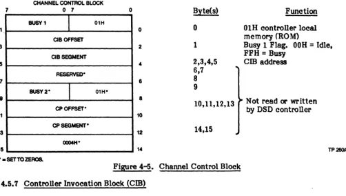
The channel control block, the next block in the control chain, requires 16 bytes as shown in Figure 4-5. The last ten bytes in this block are not read or written. They are shown for compatibility with iSBC operation only. Of the first six bytes, the first byte must contain a value of 01H. If this byte does not contain a value of OlR when checked by the controller, processing ceases with no status retumed, and an error is indicated by LED CRI (ERR). The second byte is the busy flag. It informs the host whether the controller is busy (FFH), or idle (00 H). The busy nag is pc:lSted when the controller is busy processing a command, and cleared after the command is completed. This information is used in handshaking and status commands between the host and the controller. The next four bytes contain the offset and segment (address) of the CIB, the next block in the chain.
(
7
1
3
5 7
9
11
13
15
NOTE
-The address of the CCB and cm are stored within the controller while processing the first I/O start command after a reset. These locations MUST NOT be changed without a controller reset and initialization sequence.
CHANNEL CONTROl BLOCK
o 7 o Byte(s) Function
BUSV1
I
01H0 0 01H controller local
memory (ROM)
CIBOFFSET
2 1 Busy 1 Flag. OOH
=
Idle,CIBSEGMENT FFH
=
Busy4 2,3,4,5 cm address
RESERVED' 6,7
8 8
BUSY 2"
I
01H" CPOFFSET*9
8 Not read or written
10,11,12,13
by DSD controller
10
CPSEGMENT·
12 14,15
OQ04H"
14 TP 260182
" - SET TO ZEROS.
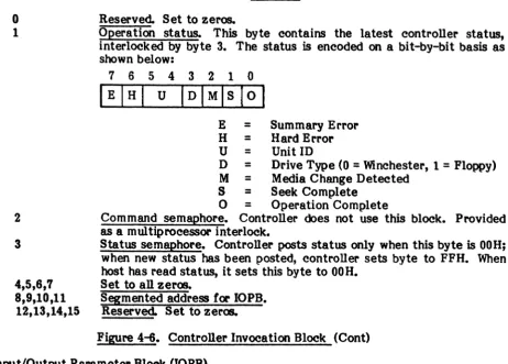
Figure 4-5. Channel Control Block ( 4.5.7 Controller Invocation Block (Cm)
(
The DSD Controller uses the
cm
to pest status to the host. The functions of each byte are shown in Figure 4-6.7
3 5 7 9
11
13
15
CONTROLLER INVOCATION BLOCK
o 7
OPERATION
RESERVED-STATUS
STATUS COMMAND
SEMAPHORE SEMAPHORE
OOH
OOH
IOPBOFFSET
IOPB SEGMENT
RESERVED-" = SET TO ZEROS.
o
o
2
8 8
10
12 14
[image:30.624.44.546.142.426.2]TP 281182
Figure 4-6. Controller Invocation Block
• CCB POINTS HERE
(
Byte(s)
o
1
2
3
4,5,6,7 8,9,10,11
12,13,14,15
Function Reserved. Set to zeros.
Operation status. This byte contains the latest controller status, interlocked by byte 3. The status is encoded on a bit-by-bit basis as shown below:
7 6 5 4 3 2 1 0 IEIHI U IDIMlslOI
E
=
Summary Error H = Hard Error U = Unit IDD = Drive Type (0 = Winchester, 1 = Floppy) M = Media Change Detected
S = Seek Complete
o
=
Operation CompleteCommand semaphore. Controller does not use this block. Provided as a multiprocessor interlock.
Status semaphore. Controller posts status only when this byte is OOH; when new status has been posted, controller sets byte to FFH. When host has read status, it sets this byte to OOH.
Set to all zeros.
[image:31.615.93.556.60.391.2]Segmented address for IOPB. Reserved. Set to zeros.
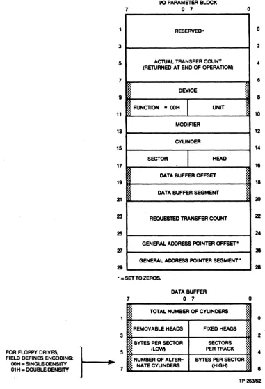
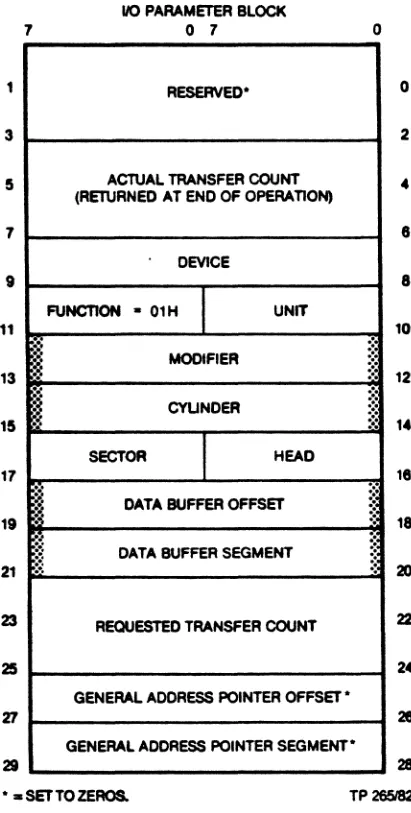
Figure 4-6. Controller Invocation Block (Cont) ( 4.5.8 Input/Output Parameter Block (lOPB)
The IOPB is the main channel for communication between the controller and the host CPU. Information required by the controller for each command is stored in this block. The IOPB and its content is shown in Figure 4-7.
The first four bytes in Figure 4-7 are reserved for future expansion. These fields should always be set to zero by the host driver to insure continUed compatibility. This is true for all reserved fields in the commands that follow.
• Actual Transfer Count: This four-byte field specifies the number of bytes transferred in the process of executing a command. It is treated as a 32-bit positive number. Byte four of the IOPB contains the least significant byte, byte seven contains the most significant. For normal disk data transfers without error, the actual transfer count will equal the requested transfer count. A count of six is indicated following a track formatting function and a count of 12 after a status transfer function.
•
Device: OOOOH 0001H 0010HThis word specifies the device type to be accessed:
=
Eight-Inch Winchester Drive (iSBC 215 equivalent>=
Floppy Disk Drive (iSBX 218 equivalent)=
Streaming Tape Drive.
• Function: This single-byte field specifies the operation to be performed; read, write, format, etc. The byte value determines how some other fields in the IOPB are interpreted. These are described in detail in paragraph 4.7.
• Unit: This field specifies which disk drive, of the drive type selected by the device
(
(
17161514131211101
Volume: _ _ _ _ _ _ _ _ _ _
--'t
~,
.... -'--
Unit:o
=
Fixed, 1=
Removable 0 through 3• Modifier: This word is treated by the controller as a field of single-bit control flags. The bits, independent of each other, are assigned the following functions:
Bit(s) 15:-8
7-3
2
1
o
Function (Enabled when bit is set to 1)
Specifies the diagnostic test to be executed when the operation specified in the function byte is the diagnostic command (Function
=
OFH). For all other commands, this byte must be set to zero.Reserved.
Allows read data, read to buffer and verify, write data, and write buffer data functions to be modified to read or write deleted data. 0= normal data; 1
=
deleted data.Inhibits automatic retries for errol' recovery when set to 1. Suppresses interrupt on command completion when set to 1.
• Cylinder: This word specifies the starting cylinder (track) number where a read, write, or format command begins. The range of acceptable values depends upon the drive type and drive parameters specified at initialization. The smallest cylinder number is always O. An illegal value causes the selected drive head to go ~o cylinder 0, and an error will be returned.
• Sector: This byte is functionally similar to the cylinder word. It specifies the starting sector number for disk read or write operations. The range of legal values depends on the drive type and format (number of sectors per track). The smallest sector number for a floppy disk is always 1, not 0 as for cylinder and head numbers. The smallest sector number for a Winchester drive is O.
• Head: This byte is also similar to the cylinder word in function. It specifies the
starti~ head number for disk read or write operations. The range of legal values
depend upon drive type. Like cylinder numbers, head numbers start at zero. For single-sided floppy disks the head number is always O. For double-sided disks the only values allowed are 0 and 1. The controller can address heads 0 through 7.
• Data Buffer Address: This four-byte field contains the segmented address of the data buffer. For normal read or write operations, this is the address of the multibus memory buffer where data are stored or fetched. For some commands, this is the address of additional control information.
• Requested Transfer Count: This four-byte field, set by the host CPU, specifies the number of bytes to be transferred in the process of executing a command. This field has the same format as the actual transfer count and is treated as a 32-bit positive number.
• General Address Pointer Address: This four-byte field is not used by the controller.
)
(
(:
7
1 3
5
7
9
11 13
15
17
19
21
23
25
11 21
110 PARAMETER BLOCK o 7
RESERVED'
ACTUAL TRANSFER COUNT
(RETURNED AT END OF OPERATION)
DEVICE
FUNCTION
I
UNITMODIFIER
CYUNDER
SECTOR
I·
HEAD DATA BUFFER OFFSETDATA BUFFER SEGMENT
REQUESTED TRANSFER COUNT
GENERAL ADDRESS POINTER OFFSET'
GENERAL ADDRESS POINTER SEGMENT' o
0
2
4
1
1
10
12
14
11
18
2D
22
24
28 28
•• SET TO ZEROS. TP26Z'82 Figure 4-'1. Input Output Parameter Block 4.6 Issuing Commands and Receiving Status
of CIB POINTS HERE
The main channel of communication is the memory-based tables. The protocol for issuing commands and receiving status is simple, straight-forward, and essentially constant for all commands. After any reset, or if controller alone is reset: put controller into reset condition, set up the WUB, CCB, and CIB as required, issue clear and start commands, and wait for not busy. For any subsequent command: set up the CCB,
cm,
and IOPB for command, issue start command and wait for interrupt or poll status semaphore. These steps are detailed as follows:A. Put controller into reset condition: Issui~ a programmed I/O reset command clears pending interrrupts and applies a hardware reset to the controller hardware. All drives are deselected. Disk writes in process are terminated. Floppy heads are unloaded.
B. Set WUB, CCB, and
cm
as required: The wake-up block is set up, pointing to the CCB, The channel control block is set up, pointing to thecm
and finally, the controller invocation block is set up. The status semaphore byte in thecm
is cleared by the host to OOH. The busy nag in the CCB is set by the host to FFH.(
C. Issue clear and start commands: Issuing a programmed I/O clear removes the hardware reset and allows the controller to recognize the start command. The first programmed I/O start command is treated in a special way when the controller has been reset. Instead of attempting to fetch an 10PB and execute a command, the controller examines the jumper settings to determine the multibus memory address of the WUB. It chains from the WUB to the CCB and
cm
internally, saving the addresses of the latter blocks. It then clears the busynag
in the CCB without issuing status.D. Wait for not busy: While the controller is collecting its table addresses, the host CPU must refrain from issuing further commands. When the busy
nag
in the CCBhas been cleared, the controller is ready to receive commands. The first commands issued must be to initialize the various disk drives in the system.
E. Set up CCB,
cm,
and 10PB for command: An 10PB is set up for the command to be executed next. Thecm
must point to the 10PB. Busy is set (FFH) in the CCB by the host.F. Issue start command: A programmed I/O start command is issued once the proper table entries have been set. This causes the controller to fetch the table contents and begin executi~ the command.
G. Wait for interrupt, or poll status semaphore: (Status will be posted) when the controller has finished execution of a command, when a seek completes, or when a disk drive becomes ready. The host CPU then examines the status to determine if
an error has occurred and to decide what command to issue next.
When the controller has status information to pass to the host, it examines the status semaphore byte in the
cm.
If it is zero, the controller assumes that previous status information has been accepted by the host. It writes the new status to the operation status byte in thecm
and sets the semaphore to non-zero. An interrupt is generated, if enabled. The host follows the reverse protocoL When the status semaphore is non-zero the host assumes the operation status byte contains new information. It fetches that information, as required, and clears the status semaphore telling the controller the status has been received. Any interrupt must be cleared by a programmed I/O clear command. Bits in the operation status byte may be decoded to determine the status type and whether an error has occurred.4.7 Controller Commands
The controller presents the programmer with a set of commands designed to take full advantage of the capabilities of the supported disk drives. These include normal read and write commands, commands to tailor the disk system for different applications, and a complete set of diagnostics. These commands are invoked by setting up the described functions and executing a programmed I/O start command to the controller. The following paragraphs detail the 10PB and data buffer requirements for each command executed by the controller. The command to be executed is determined by the function field in the 10PB.
Value (Hex)
ooR
01H 02H 03H 04H 05H 06H 07H
Function Initialize
Transfer Status Format
Read Sector ID Read Data
Read to Buffer and Verify Write Data
Value (Hex) 08H
09H - ODH OEH
OFH 80H 81H 82H 83H 84H
Function
Initiate Track Seek Reserved
Buffer I/O Diagnostic
Reset Tape Drive Disk Image Backup Disk Image Restore Read Tape Status
Retension Tape Cartridge
The followiqr description of each function includes a diagram of the IOPB showing those
fields (shaded blocks) that must be set by the host CPU before the command is executed.
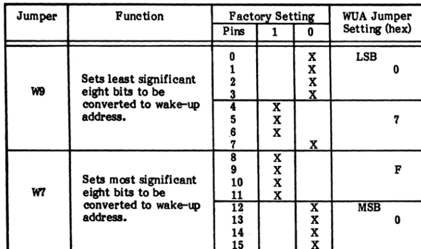
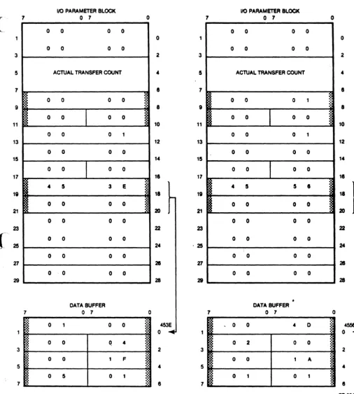
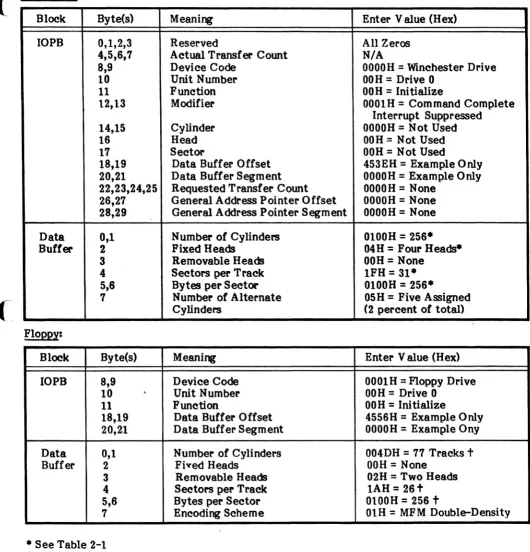
4.7.1 Initialize (DOH)
The initialize function (See Figure 4-8) is used to transfer drive related parameters to the controller and to seek drive heads to cylinder zero to synchronize position. These parameters include the number of cylinders, heads, bytes per sector, etc. The information
passed to the controller is contained in lin extension to the IOPB. This eight-byte extension is
addressed by the data buffer offset and segment stored in the IOPB.
Information in the 10PB extension is used by the controller for all disk related
commands. The initialize function command should be issued for each drive in the system following any hardware reset caused by power-on, Multibus INrr" or a programmed I/O reset command. Commands issued for drives not initialized will not be executed and an error will be retumed.
The fields in the lOPS extension block hav. the following meaniqr:
• Number of Cylinders: This word specifies the number
ot
physical cylinders availableon a disk drive. Refer to Section 2 of this manual for the proper word value for
drives supported by the controller. It this word is set to zero, the initialize function
command removes the specified drive from use as if an initialize command had not been issued since the last reset.
• Fixed Heads: This byte specifies the number of fixed heads on the drive. For
example, a 40 megabyte Quantum Winchester drive has eight. This byte is ignored
when a noppy drive is initialized. .
• Removable Heads: This byte specifies the number of heads on a noppy disk drive.
For a single-sided noppy drive, the value is one. For a double-sided drive, the value is two. When a Winchester drive is specified, this byte is ignored.
• Sectors per Track: This byte specifies the number of sectors per track for the drive
specified. Reier to Section 2 of this manual for the proper byte value.
• Bytes per Sector (Low) and Bytes per Sector (High): These two bytes form a word
specifying the number of data bytes in a disk sector. This sector length must match the format for the disk, and must be 128, 256, 512, or 1024.
> • • Number of Alternate C linders or Encodl : For a Winchester drive, this byte
speci les the number 0 cylinders reserved as alternates for defective tracks. Por a
noppy drive, this byte specifies the data encoding scheme to be used; OOH for FM,
single-density and 01R for MFM, double-density.
(
<-'
1 3 5 7 9 11 13 15 17 19 Z1 23 25 Z1 29 7"i
rt
110 PARAMETER BLOCK
o 7 .
RESERVED-ACTUAL TRANSFER COUNT (RETURNED AT END OF OPERATION)
DEVICE
m
FUNCTION - OOHI
UNIT MODIFIERCYUNDER
SECTOR
I
HEAD DATA BUFFER OFFSET DATA BUFFER SEGMENTRECUESTED TRANSFER COUNT
GENERAL ADDRESS POINTER QFFSE1'.
GENERAL ADDRESS POINTER
SEGMENT-o
~~
:' §
:'
" "
~
~
~~
.~
- - SETTO ZEROS.
3
FOR FLOPPY DRIVes.
t-
57 FIELD DEFINES ENCODING:OOH. SlNGLE-DENSITY 01H. DOUBLE-DENSITY
7
DATA BUFFER
o 7
I
TOTAL NUMBER OF CYUNDERS~:~REMOVABLE HEADS FIXED HEADS
:.
::;: BYTES PER SECTOR seCTORS
ij (LQWt PER TRACK
o ~ ~ " ',' :.: ,', ,', .:.
.
::3 .:. ','l
NUMBER OFALTER-NATE CYUNDERS BYTES PER SECTOR (HIGH)
j
• [image:36.617.60.442.40.599.2]o 2
..
8 8 10 12 14l'
18 20 22 21 21 o 2 8 TP283182Figure 4-8. IOPB Initialize Function
Figure 4-9 illustrates the IOPB set up for initialization of an SAI004 type Winchester and an SA8S0 type floppy drive. The addresses used in the figure are for illustrative purposes only and not intended for actual use.