Scholarship@Western
Scholarship@Western
Electronic Thesis and Dissertation Repository
8-24-2016 12:00 AM
Parametric Design, Modeling, and Optical Evaluation of
Parametric Design, Modeling, and Optical Evaluation of
Retroreflective Prismatic Structures
Retroreflective Prismatic Structures
Sama Hussein
The University of Western Ontario
Supervisor
Dr. Remus Tutunea-Fatan
The University of Western Ontario Joint Supervisor Dr. Evgueni Bordatchev
The University of Western Ontario
Graduate Program in Mechanical and Materials Engineering
A thesis submitted in partial fulfillment of the requirements for the degree in Master of Engineering Science
© Sama Hussein 2016
Follow this and additional works at: https://ir.lib.uwo.ca/etd
Part of the Automotive Engineering Commons, Computer-Aided Engineering and Design Commons,
Manufacturing Commons, Optics Commons, and the Other Mechanical Engineering Commons
Recommended Citation Recommended Citation
Hussein, Sama, "Parametric Design, Modeling, and Optical Evaluation of Retroreflective Prismatic Structures" (2016). Electronic Thesis and Dissertation Repository. 4022.
https://ir.lib.uwo.ca/etd/4022
This Dissertation/Thesis is brought to you for free and open access by Scholarship@Western. It has been accepted for inclusion in Electronic Thesis and Dissertation Repository by an authorized administrator of
ii
Retroreflectors (RR) are defined as passive optical structures that redirect incident light to its
originating source. Specific types of retroreflectors called inverted cubes (ICs) function
through total internal reflection (TIR) and are used in various applications such as
measurement tools, traffic signs and automotive rear and side lighting. This thesis aims to
model, analyze, fabricate and study a novel type of IC retroreflectors called right triangular
prism (RTP). A parametric approach is used to model existing IC geometries from a generic
unit cube and is then implemented to model the novel RTP geometry. Those elements are then
tested by optical simulation software in single element and areal forms and their performances
are compared. Moreover, fabricated prototype arrays of RTPs were separately tested using a
digital lux meter and a luminance imaging system. Both virtual and physical optical
experimentation proved that the newly designed RTP structure is indeed functional and have
the potential to be used in many applications.
Keywords
Micro-optics, Retroreflector, Right Triangular Prism, Inverted Cube Retroreflector,
iii
Co-Authorship Statement
Chapter 1: Sama Hussein – wrote manuscript
Chapter 2: Sama Hussein – designed study, performed analysis, wrote manuscript
Benjamin Hamilton – reviewed fabrication manuscript
Evgueni Bordatchev – supervised work, wrote and reviewed manuscript
Remus Tutunea-Fatan – supervised work, reviewed manuscript
Chapter 3: Sama Hussein – designed study, performed analysis, wrote manuscript
Benjamin Hamilton – fabricated arrays, performed analysis, wrote manuscript
Evgueni Bordatchev – supervised work, reviewed manuscript
Remus Tutunea-Fatan – supervised work, reviewed manuscript
Chapter 4: Sama Hussein – designed study, performed analysis, wrote manuscript
Benjamin Hamilton –fabricated arrays
Remus Tutunea-Fatan – supervised work, reviewed manuscript
Evgueni Bordatchev – supervised work, reviewed manuscript
iv
Dedications
This thesis is dedicated to my loving parents as they have always inspired me to learn, and
v
Acknowledgments
First and foremost, I would like to deeply thank my supervisors, Dr. Remus Tutunea-Fatan and
Dr. Evgueni Bordatchev for the unconditional support and encouragement they have provided
throughout my degree. Dr. Tutunea, words cannot express my appreciation for all the help,
patience and overtime you granted me. You always made yourself available regardless of your
schedule and I always knew you will be present to address any concerns. Dr. Bordatchev, thank
you for your invaluable advice and support. You were always patient with me and always
willing to put some time aside for the sake of research. Truly your guidance was beyond the
scope of a normal supervisor.
I would also like to thank my research partners Ben Hamilton and Nicolas Milliken. Ben, you
have always been a great example an ethical, trustworthy and supportive peer, and I have really
enjoyed working along with you. Nic, your help with the experiments was priceless and it has
really been a great privilege working with you. I wish you all the best with the rest of your
work.
In addition, I would like to thank my colleagues Shirzad Mohajerani, Mohammadreza Faieghi,
Navraj Heer, Mahdi Bagheripoor, and Josh Miller for being a part of this trip and for offering
a hand when needed.
My masters would have been much more difficult without the continuous moral support and
advice my friends Somiraa Said and Melissa Salem have given me. Somiraa, I am genuinely
grateful for every moment you were there with me, and for your constant guidance. Melissa,
your cheerful presence was always a great relief to all my worries and concerns.
I would like to express my sincere gratitude to my parents, Alaa Abuldhady and Doaa Lashin,
as they have sacrificed so many things in their lives to invest in my education and have always
been there for me with their never ending support.
I am sincerely grateful to the “Ontario Graduate Scholarship” and the “BMO Financial Group
Ontario Graduate Scholarships” as I have had the privilege to hold this honorable award. Finally,
this research was conducted in collaboration with Canada’s National Research Council (NRC) that
vi
Table of Contents
Abstract ... ii
Co-Authorship Statement... iii
Dedications ... iv
Acknowledgments... v
Table of Contents ... vi
List of Tables ... ix
List of Figures ... x
List of Appendices ... xv
List of Abbreviations ... xvi
CHAPTER 1: Introduction ... 1
1.1 Micro-Optics ... 2
1.2 Micro-Optical System Modeling ... 3
1.3 Retroreflectors... 4
Types of Retroreflectors ... 5
Optical Evaluation Metrics of ICs ... 7
Applications of Retroreflectors ... 8
Inverted Cube Retroreflectors ... 10
1.4 Rationale ... 12
Motivation ... 12
Contributions... 14
Objective ... 14
Thesis Overview ... 15
1.5 References ... 16
vii
2.1 Overview ... 19
2.2 Introduction ... 19
2.3 Working Principles, Fabrication and Typical Designs ... 21
2.4 Parametric Modeling Framework ... 27
2.5 Summary and Conclusions ... 30
2.6 Acknowledgments... 31
2.7 References ... 31
CHAPTER 3: Novel Retroreflective Micro-Optical Structure for Automotive Lighting Applications ... 33
3.1 Overview ... 34
3.2 Introduction ... 35
3.3 Optical Functionality and Geometric Modeling ... 36
3.4 Optical Simulation and Analysis of Prismatic RR Micro-Optics ... 42
3.5 Conventional Fabrication of Automotive Retroreflective Optics ... 50
3.6 Limitations of Conventional Fabrication Methods in RTP Fabrication ... 52
3.7 Single Point Inverted Cutting in RTP Fabrication ... 57
3.8 Fabrication of the Prototype RTPs ... 61
3.9 Experimental Evaluation of Optical Performance of Prismatic RR Micro-Optics 62 3.10 Summary and Conclusions ... 65
3.11 Acknowledgments ... 66
3.12 References ... 66
CHAPTER 4: Comparative Analysis of Inverted Cube Retroreflectors ... 68
4.1 Overview ... 69
4.2 Introduction ... 69
4.3 Geometries of Basic Retroreflective Micro-optical elements ... 72
viii
Right Triangular Prisms ... 77
4.4 Comparative Analysis of Retroreflective Micro-optics ... 79
Single Element Optical Performance Analysis ... 81
Areal Optical Performance Analysis ... 86
4.5 Fabrication of IC RRs ... 89
4.6 Optical Performance of Fabricated Micro-Optical Elements ... 90
4.7 Summary and Conclusions ... 92
4.8 Acknowledgments... 93
4.9 References ... 93
CHAPTER 5: General Discussion and Conclusions ... 95
5.1 Summary ... 96
5.2 Conclusions ... 97
5.3 Strengths and Limitations ... 99
5.4 Future Recommendations ... 99
5.5 References ... 100
Appendix ... 101
ix
List of Tables
Table 3.1: Dependence between ICC RR aperture geometry and trimming plane location .. 40
Table 4.1: Parameters of HA ICC ... 75
Table 4.2: Parameters of TA ICC ... 76
Table 4.3: Parameters of an RTP ... 79
Table 4.4: Setup distances – single element analysis... 81
x
List of Figures
Figure 1.1: Total internal reflection ... 5
Figure 1.2: Lens and mirror retroreflector ... 6
Figure 1.3: Working principle of CC and IC RRs ... 7
Figure 1.4: Inverted cube retroreflector ... 11
Figure 1.5: Types of inverted cube (IC) retroreflectors ... 12
Figure 1.6: Product development process ... 13
Figure 2.1: Principal retroreflector designs ... 20
Figure 2.2: Optical functionality of the retroreflectors ... 21
Figure 2.3: Correlation between the optical efficiency of the RR and its included angle ... 22
Figure 2.4: Phased fabrication of master electroforms ... 23
Figure 2.5: Typical RR geometries ... 24
Figure 2.6: The effect of manufacturing defects on the optical performance of the RRs ... 26
Figure 2.7: Types of parameters controlling the design of automotive rear lighting ... 27
Figure 2.8: Representative sample of an automotive taillight ... 29
xi
Figure 3.1: Retroreflectors: optical functionality and structure ... 36
Figure 3.2: Working principle of a typical TIR-based RR element ... 37
Figure 3.3: Geometrical definition of the ICC RR: a) original unit cube to be rotated with θ about n and b) trimming plane (h || V || k) ... 39
Figure 3.4: Top view of the three main ICC RR ... 40
Figure 3.5: Geometrical definition of the RTP: a) original unit cube; b) rotation with β around X-axis; c) scaling along X axis and d) horizontal trimming of the unit cube ... 41
Figure 3.6: Front view of the three analyzed RTP geometries ... 43
Figure 3.7: Geometric parameters of the right triangular prism ... 44
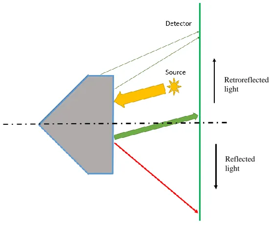
Figure 3.8: Received versus lost light in RTP retroreflector ... 45
Figure 3.9: Optical software setup ... 46
Figure 3.10: The relationship between the incidence angle and output power ... 47
Figure 3.11: Retroreflected versus reflected power output ... 48
Figure 3.12: Retroreflected and reflected power for scenario 1 ... 48
Figure 3.13: Retroreflected and reflected power for scenario 2 ... 49
Figure 3.14: Retroreflected and reflected retroreflection for scenario 3 ... 49
xii
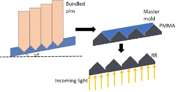
Figure 3.16: Generation of RR elements by means of the conventional pin-bundling
technology ... 51
Figure 3.17: Fabrication of RTPs by means of pin-bundling technology ... 52
Figure 3.18: Pocket-like structures associated with conventional fabrication of RTPs on non-planar and/or inclined surfaces ... 53
Figure 3.19: Representative cross-section through an automotive taillight ... 53
Figure 3.20: Theoretical pocket-less RTP geometry for inclined surfaces ... 54
Figure 3.21: Optical setup used to assess the performance of the pocket-like manufacturing imperfections... 55
Figure 3.22: Optical setup used to assess the performance of the theoretical pocket-less structures ... 56
Figure 3.23: Scattering/non-scattering effects associated with: a) conventionally fabricated RTPs and b) theoretical RTPs ... 57
Figure 3.24: Single point inverted cutting kinematics (adopted from (Hamilton et al., 2015)) ... 58
Figure 3.25: Single point inverted cutter for RTP fabrication ... 59
Figure 3.26: Single point inverted cutting kinematics for RTP fabrication... 60
xiii
Figure 3.28: Visual aspect of the RTP prototype: a) macroscopic overview and b) detailed
SEM imaging ... 62
Figure 3.29: Comparative visual/qualitative assessment of the conventional ICC and proposed RTP RR ... 63
Figure 3.30: Physical setup used to evaluate the retroreflected light ... 64
Figure 4.1: Inverted cube retroreflector ... 71
Figure 4.2: Study methodology for designing, analyzing, fabricating and testing IC RRs ... 72
Figure 4.3: Originating inverted cube of ICC elements ... 73
Figure 4.4: Parameters of an HA ... 74
Figure 4.5: Parameters of a TA ... 76
Figure 4.6: Originating unit cube of an RTP ... 77
Figure 4.7: Parameters of an RTP ... 78
Figure 4.8: Optical simulation setup ... 80
Figure 4.9: Definition of input, output and lost lights ... 81
Figure 4.10: Comparision between RRE of RTP, HA, and TA with constant reflective area ... 83
Figure 4.11: Dead zones of a TA RR ... 84
xiv
Figure 4.13: Comparision between RRE of RTP, HA, and TA with constant aperture area 86
Figure 4.14: Cross talking of IC RR elements ... 87
Figure 4.15: Arrays of a) RTP, b) HA ICC, and c) TA ICC elements ... 88
Figure 4.16: Comparative analysis between RRE of arrays of RTP, HA and TA geometries
... 89
Figure 4.17: Prototyping and mass production of IC RRs through diamond cutting ... 90
Figure 4.18: a) Camera image and b) LMK LabSoft luminance image of RTP andHA RR
xv
List of Appendices
Appendix A: Minimum millicandelas per incident lux for a red reflex reflector developed
xvi
List of Abbreviations
CAD computer-aided design
CAM computer-aided manufacturing
CC corner cube
IC inverted cube
ICC inverted corner cube
HA hexagonal aperture
LED light emitting diode
OEM original equipment manufacturer
PMMA polymethyl methacrylate
RR retroreflector
RRE retroreflection efficiency
RTP right triangular prism
SEM scanning electron microscopy
TA triangular aperture
TIR total internal reflection
1.1
Micro-Optics
The technology of micro-optics was initiated 20-30 years ago and since then has been
emerging in various fields ranging from medicine to entertainment. The term micro-optics
can be distinguished from optics through different aspects. For instance, it can be seen as
the field of studying and designing optics at a miniature level (i.e. sub mm and sub µm
level). However, some argue that there is no explicit definition of micro-optics in terms of
size, and therefore, should be defined based on its microfabrication techniques (Herzig,
2000; Sinzinger and Jahns, 2006; Zappe, 2010).
Although the expression of micro-optics only appeared in the 1980s (Iga et al., 1984), some
components have been around from before. The development of micro-optics was limited
by the high-cost microfabrication processes. For instance, in 1874 Lord Rayleigh started
using gratings for spectroscopy instead of prisms as they showed better resolution, but
those gratings did not replace prisms in this application until the 1950s due to their
expensive fabrication process. The costs of the manufacturing process later reduced with
the developing replication technology which opened the door for mass producing
high-precision gratings from a single expensive master piece (Zappe, 2010). This replication
process later opened the opportunity to a wide range of applications and is still one of the
main processes used in fabrication of micro-optics till the today.
Present-day field of micro-optics is associated with various technologies that continue to
broaden its scope of applications (Borrelli, 2004; Sinzinger and Jahns, 2006; Kress and
Meyrueis, 2009; Zappe, 2010). Fabrication techniques of micro-optics can be branched
into two subdivisions: lithographic such as optical, electron beam, X-ray, and
The arrival for the lithographic techniques provided new opportunities for fabrication of
micrometer accuracy diffractive micro-optics and microlenses (Sinzinger and Jahns, 2006;
Zappe, 2010). Non-lithographic techniques, on the other hand, such as diamond cutting are
being recently inspected in an effort to further reduce fabrication costs and produce
complex geometries (Sinzinger and Jahns, 2006). Moreover, extra precise processes such
as diamond micro chiseling are being investigated to create further complex optical
elements whose geometries are a limit to the available machining capabilities. This process
can be very helpful in miniaturizing optical elements such as reflective or refractive
elements, used for automotive lighting, and reflective foils for traffic signs or safety
garments to a scale of a few microns (Herzig, 1997; Brinksmeier et al., 2008; Brinksmeier
et al., 2012b; Hamilton et al., 2016b).
1.2
Micro-Optical System Modeling
The science of micro-optics can be understood through designing practical systems that
control passive (e.g. taillight retroreflectors) and active (e.g. automotive headlamps) optical
elements to achieve the required results. Computer and modeling simulations are very
useful tool as they save an optical engineer cost and time. Optical simulation systems work
through ray tracing, in which a light ray is envisioned as a line normal to the direction of
the electromagnetic wave propagation. As a light ray passes through different optical
elements, the computer recalculates the direction of the rays by following the basic optical
concepts such as transmission, reflection, refraction, etc. A ray tracing system can be
divided into two major parts: sequential and non-sequential modeling. A sequential model
non-sequential ray tracing, the rays do not necessarily hit the optical elements in the order
they are placed in (Taylor, 2000).
1.3
Retroreflectors
Retroreflection is the optical phenomenon in which light is guided to a direction that is
opposite and parallel to that of the originating source, and the passive optical structures
that help achieve this aspect are called retroreflectors (RRs). RRs are commonly used in a
wide scope of applications such as metrology, road safety and interferometers (Liepmann,
1994).
Retroreflectors operate using two simple optical concepts: reflection and refraction.
Reflection is the redirection of light to an angle equal in magnitude and opposite in
direction to the incidence angle, while refraction is the deviation of a light ray as it passes
from one medium to another which can be expressed through Snell’s law (Equation 1.1).
2 1 2
1
sin sin
n n
[1.1]
Generally, when a light ray passes from a region of a high refractive index to one with
lower refractive index, a portion of that light gets reflected and the rest are refracted away
from the normal so that the angle of refraction is greater than the incidence angle. When
the incidence angle reaches a certain critical angle, θc, the light exits at an angle of 90° to
the normal. Moreover, if the light strikes the medium at any angle greater than that critical
angle, it gets completely reflected and no refraction occurs. This phenomenon is called
refractive indices of the two mediums through Equation 1.2, where n1 and n2 are the
refractive indices of the first and second mediums, respectively.
1 2 1 sin n n c [1.2]
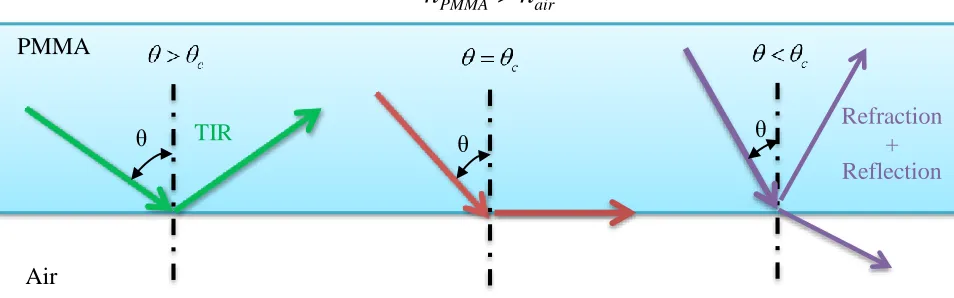
Figure 1.1 shows an example of a light ray passing from polymethyl methacrylate, PMMA,
(nPMMA=1.492) to air (nair= 1) at different angles of incidence. The critical angle in this case
is 42.11°. Therefore, if the light hits the air at an angle greater than 42.11°, TIR will take
place and all the light will be reflected; if it strikes the air at angle equal to 42.11°, the
refracted way will travel along the surface of PMMA, and if it hits at an angle lower than
42.11°, it will be refracted.
Figure 1.1: Total internal reflection
Types of Retroreflectors
There are different types of retroreflectors that essentially all serve the same purpose but
used in commercial applications are lens and mirror, corner cube (CC) and inverted cube
(IC) retroreflectors.
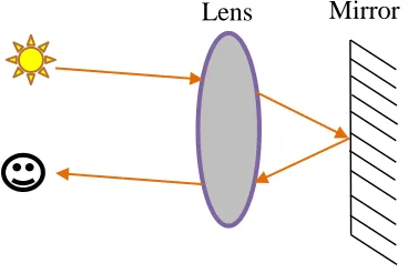
Lens and mirror, also known as cat’s eye, RRs are commonly used as warning and traffic
calming devices in local roads and highways such as in the retroreflective sheets used on
stop signs (Medicus, 2006). As their name indicates they consist of a lens and a mirror
which work together to achieve retroreflection as seen in Figure 1.2. This setup functions
in a similar pattern to a cat’s eye, which glows at night when light is directed towards it.
Figure 1.2: Lens and mirror retroreflector
On the other hand, corner cube (CC) RRs use two or three reflective surfaces to achieve
retroreflection. This type of RR simply works by reflecting light rays from one reflective
facet to another until they end up being oriented in a direction that is opposite and parallel
to that of the originating source. Those reflective facets can be made of mirrors or highly
polished metal surfaces.
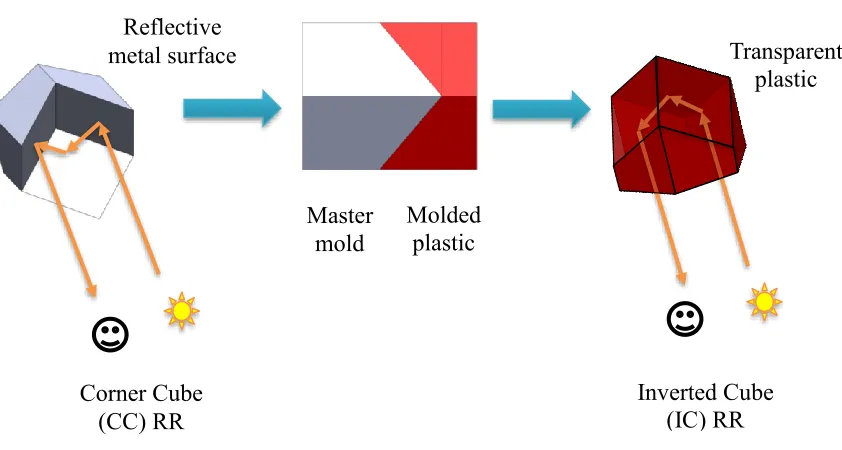
If a corner cube (CC) element were to be used as a master mold, the product mold would
be in the shape of an inverted cube (IC) as shown in Figure 1.3, i.e. ICs represent the
opposite/reverse side of the CCs. Inverted cubes function in a very similar manner to CCs
but by reflecting light through TIR. They are usually made of transparent materials such as
glass or plastic and they depend on the fact that the refractive indices of these materials are
higher than that of air. Figure 1.3 shows images of CC and IC RRs retroreflecting light.
Figure 1.3: Working principle of CC and IC RRs
Optical Evaluation Metrics of ICs
There are five main metrics used to evaluate the optical performance of an RR:
retroreflection efficiency, divergence, angularity, brilliancy. and effective retroreflective
area. Retroreflection efficiency (RRE) is the ratio of retroreflected light to the incident
light. Divergence evaluates the amount of deviation of the retroreflected light from the
incidence light, whereas, angularity corresponds to range of incidence angles at which the
RR is able to function and is greatly limited by the critical angle needed for TIR to occur
in an IC RR. Brilliancy is the retroreflection efficiency at specified observation angles
(Lundvall et al., 2003). The aforementioned four optical evaluation metrics can be used to Molded
plastic Master
mold
Corner Cube (CC) RR
Inverted Cube (IC) RR
Transparent plastic
TIR Reflection
evaluate any RR. Effective retroreflective area, on the other hand, can only be related to
CC or IC RRs and it correlates to the percentage of incident facet area participating in
retroreflection (Kim and Lee, 2007).
Some of those performance specifications are inversely related to each other. Therefore, it
is important to fabricate the RRs to fit the required criteria according to various
applications. For instance, RRE and divergence angles are the most essential prerequisites
of an RR used in safety applications (Yuan et al., 2002). Therefore, RRs used in automotive
tail and side lightings are required to follow specific safety standards that dictate certain
amount of RRE at given divergence angles.
Applications of Retroreflectors
Lens and mirror RRs are typically used for safety applications as they have a wide
angularity, whereas, CC and ICC RRs are preferred in measurement applications as they
require higher RRE (Seward and Cort, 1999; Brinksmeier et al., 2012a). However, all three
RRs are often interchanged in many fields of applications due to specific requirements (e.g.
RRE) or limitations (e.g. cost).
For instance, CC RRs have been used for Lunar Laser Ranging after the Apollo mission
planted 11 retroreflective arrays on the moon in 1969 (Erickson, 2011). Since then, they
have produced comprehensive information about the crust and interior of the moon and
have resulted in some of the best tests in the field of general relativity (Currie et al., 2011).
Moreover, RRs have been used in the traffic world for many years. In 1920s RRs were first
introduced to traffic signs by attaching relatively large glass spheres (10 mm - 20 mm) or
signs, however, have their history in the miniaturization of these two retroreflective
elements. In the 1930s, glass spheres, which act as lens and mirror RRs, of a diameter less
than 1 mm were first used in the cinemas to produce much brighter images. Those glass
spheres later went through a development process by 3M in an effort of integrating them
in traffic signs and road pavements. The first glass beads embedded sheeting was implanted
on outskirts in 1939 which later developed into a commercial sheeting product. Those
sheets, however, only retroreflected at most 8% of the light. In 1971, 3M launched its new
high intensity sheeting that has an RRE of 16% after applying refinements to both the
retroreflective elements and the adhesive layer in which the glass spheres were enclosed.
This sheeting was intensively used in major traffic signs mostly on high speed roads where
night time visibility is a safety issue and is still used until today (Lloyd, 2008).
On the other hand, micro-prismatic sheeting, which acts as an array of IC RRs, was
patented by the American Rowland brothers in 1970 and was first commercialized in 1973.
In the 1989 3M launched its so-called “Diamond Grade” micro-prismatic sheeting which
retroreflected 35% of incident light and proved to be more efficient than the glass beads
sheets. Moreover, those micro-prismatic sheets provided refinement to car headlight
designs and allowed them to focus more light onto the road surface which in turn was able
to reduce the light on the roads. Those IC RR elements were and still are best suited to
conditions where long range visibility is essential and where the direction of the oncoming
traffic is head on (Lloyd, 2008). However, prismatic structures had some limitations as
they were more expensive to fabricate, and less effective when viewed from wide angles
(So et al., 2002; Lundvall et al.), and therefore the glass bead sheets are still commonly
Nowadays the performance of retroreflective prismatic sheeting can be tailored to required
applications through computer-aided design (CAD) and computer-aided manufacturing
(CAM) technologies and are still continuously developing while trying to cut down their
costs. Hence, it seems that although both micro-prismatic and glass beads retroreflective
elements continue to coexists, the future potential mainly lies in the newly developing
prismatic elements (Lloyd, 2008).
Furthermore, IC RR arrays, better known as reflex reflectors, are integrated in the
automotive vehicles’ rear and side lighting lamps to provide safety and visibility of the
preceding traffic and safety standards are used to guide the performance of those RRs
(Wördenweber et al., 2007; SAE, 2009). For instance, SAE standards require vehicles to
have a minimum of two red RR arrays on the rear of the vehicle on each side of the
centerline, and two arrays on each side of the vehicle, the front being amber in color and
the back one being in red (Wördenweber et al., 2007). This standard also provides other
information guiding the position, reflectivity, area and visibility of the RR arrays integrated
in rear and side lighting (SAE, 2009).
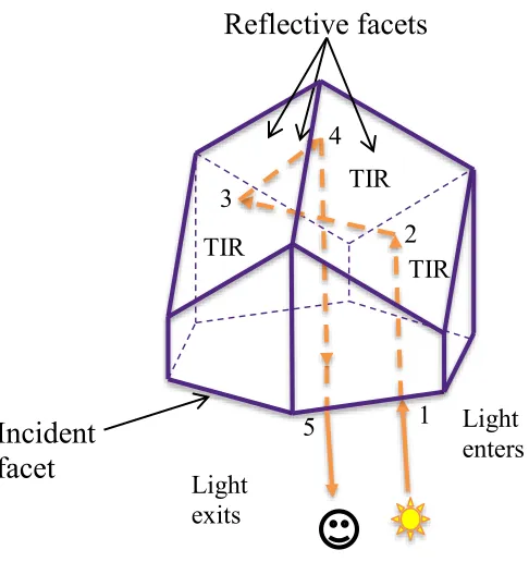
Inverted Cube Retroreflectors
Previous studies indicate that inverted cube retroreflectors acquire higher retroreflection
efficiency than both corner cube and lens and mirror retroreflectors as the reflectivity
acquired through TIR is higher than that acquired by normal reflection (Yuan et al., 2002;
Lloyd, 2008). Figure 1.4 shows the approach through which the reflective facets of a typical
IC RR work together to achieve retroreflection. The light first enters through the incident
through TIR, and then to the third and finally leaves the RR element in a direction to that
of the incident one.
Figure 1.4: Inverted cube retroreflector
Present day commercial applications use a specific type of ICs called inverted corner cube
(ICC) which consists of three reflective orthogonal facets. ICCs have been used for decades
in safety applications in the form of triangular and hexagonal aperture elements. This thesis
however focuses on introducing, modeling, fabricating and testing a novel type of IC
elements that consists of two reflective facets called right triangular prism (RTP). In
addition, all types of ICs outlined in Figure 1.5 will be further modeled and elaborated on. 1
2 3
4
5
Incident
facet
Light enters Light
exits
Reflective facets
TIR
Figure 1.5: Types of inverted cube (IC) retroreflectors
1.4
Rationale
Motivation
The master mold used to produce IC RR arrays is usually fabricated by means of a method
called pin bundling technique (Van Arnam, 1981; Brinksmeier et al., 2008). Molds
produced through this technique could take up to about 14 weeks and could cost around
$2000/in2-$3000/in2, which implies that this fabrication method is both expensive and time
consuming. Furthermore, this fabrication approach represents a limiting factor for both
geometrical complexity and dimensional size of the retroreflectors that can only be of
inverted cube type and of approximately 1-2 mm depth. Both constraints are determined
by the geometry of the forming tip of the pin, as well as the way in which the pins are
bundled/assembled together prior to electroforming. In theory, pins with smaller cross
sectional sizes could also be used, but this will significantly increase their own
IC (Inverted Cube) ICC (Inverted Corner Cube Hexagonal Triangular
fabrication/handling costs and in turn, this will lead to higher overall mold production
expenditures.
Pin-bundling technology represents the state-of-the-art technology used in the fabrication
of the retroreflective components based on total internal reflection principles whose
primary market continue to remain automotive lighting. However, it is important to point
out that this technology has significantly restricted the geometrical diversity of this type of
retroreflectors to the point that they have only been produced in ICC shape.
As a consequence of the severe manufacturing limitations, the current ICC design was used
for decades without knowing much if it can be improved in any way in a sense that little –
if anything – was published on the functionality of IC RRs or on how their design should
be changed to improve their optical efficiency. This contradicts on many levels the classical
product development paradigm shown in Figure 1.6 according to which extensive design,
optimization and analysis should always precede the mass production phase.
Figure 1.6: Product development process
To address the aforementioned manufacturing limitation of the traditional pin-bundling
technique, ultraprecise single point inverted technique (USPIC) was developed by
Hamilton et al. (Hamilton et al., 2016a) The introduction of this new versatile fabrication
technique unlocked a practically unlimited diversity of TIR-based RR geometries, and it
Test
becomes clear that a need to develop a novel framework capable of modeling, designing,
analyzing and ranking virtually any type of retroreflective geometry exists.
Contributions
The present thesis represents one of the first attempts to propose an integrated framework
for the optical analysis of the TIR-based RRs. Hence, the major contributions of this thesis
are related to the parametric approach proposed, developed and implemented for the
modeling, designing and virtual/physical testing of new retroreflective elements called
right triangular prisms (RTPs). While these retroreflective elements might be regarded as
somewhat of a “case study” geometry in the context of the developed framework, the
analysis reported in this thesis suggests that RTPs have equivalent – if not even better –
optical performance when compared to their traditional ICC counterparts.
Objective
The main objectives of this thesis are:
1. to develop a parametric approach for designing and modeling inverted corner cube
retroreflectors (ICC RRs) from a unit cube,
2. to develop a parametric model of a novel type of retroreflective elements termed as
right triangular prism (RTP),
3. to study the optical performance of the designed and fabricated RTPs, and
4. to evaluate and compare the optical performance of the RTPs with respect to
Thesis Overview
Chapter 2 introduces the types of IC RRs and their functionalities in the scope of
automotive tail and side lighting. Optical simulation testing is used to examine the effect
of changing the orientation of the reflective facets in an IC RR as they deviate from the
perpendicularity position. Moreover, it details the conventional pin bundling fabrication
technique used to make the automotive rear and side lighting master molds, and examines
the effects of manufacturing defects on the optical performance of IC RRs specifically in
terms of retroreflection efficiency (RRE). Finally, parametric design and modeling is
introduced on three different levels for future evaluation and optimization of optical
performance of IC retroreflective elements according to the automotive tail and side
lighting industry.
Chapter 3 introduces and details the parametric approach used to model the currently used
ICC geometries from a unit cube through performing rotation and transformation
operations. This approach is then adapted and implemented to model the novel right
triangular prim (RTP) IC geometry using the same unit cube as a source and the same logic
but with different operations. The chapter then specifically examines the effect of the
presence of an illumination element on the RTP RR through a set of optical simulations.
Moreover, the fabrication of the IC RRs through both conventional pin bundling and novel
ultraprecise single point inverted cutting methods are discussed and the final geometries of
both outputs are compared. Finally, the functionality of a fabricated RTP prototype array
is tested through a real life setup.
Chapter 4 aims to use the parametric approach developed earlier in Chapter 3 to model
retroreflection efficiencies (RREs) and effective retroreflective areas. The analysis is done
via optical simulation software, OpticStudio, in which incidence angles were changed and
results were measured. Experimental luminance measuring tests were then conducted using
an RTP prototype, fabricated through ultraprecise single point inverted cutting (USPIC),
and a conventional HA ICC array to prove the functionality of the novel RTP elements and
their future potential to be commercialized in certain applications.
Chapter 5 sets a conclusion to the thesis and provides future recommendations.
1.5
References
Borrelli, N. F. 2004. Microoptics Technology: Fabrication and Applications of Lens Arrays and Devices, CRC Press.
Brinksmeier, E., Gläbe, R. & Flucke, C. 2008. Manufacturing of molds for replication of micro cube corner retroreflectors. Production Engineering,2, 33-38.
Brinksmeier, E., Glabe, R. & Schonemann, L. 2012a. Diamond Micro Chiseling of large-scale retroreflective arrays. Precision Engineering-Journal of the International Societies for Precision Engineering and Nanotechnology,36, 650-657.
Brinksmeier, E., Gläbe, R. & Schönemann, L. 2012b. Review on diamond-machining processes for the generation of functional surface structures. CIRP Journal of
Manufacturing Science and Technology,5, 1-7.
Currie, D., Dell'Agnello, S. & Delle Monache, G. 2011. A Lunar Laser Ranging Retroreflector Array for the 21st Century. Acta Astronautica,68, 667-680.
Erickson, K. 2011. What Neil and Buzz Left on the Moon [Online]. NASA. Available:
http://science.nasa.gov/science-news/science-at-nasa/2004/21jul_llr/ [Accessed July 26 2016].
Hamilton, B. W., Hussein, S., Milliken, N., Tutunea-Fatan, O. R. & Bordatchev, E. V. 2016a. Fabrication of Right Triangular Prism Retroreflectors Through 3½½-Axis Ultraprecise Single Point Inverted Cutting. Computer-Aided Design and Applications.
Herzig, H. P. 1997. Micro-Optics: Elements, Systems, and Applications, London, Taylor & Francis.
Herzig, H. P. 2000. The world of micro-optics. Leos 2000 - Ieee Annual Meeting Conference Proceedings, Vols. 1 & 2, 639-640.
Iga, K., Kokobun, Y. & Oikawa, M. 1984. Fundamentals of Microoptics, New York, Academic Press.
Kim, H. & Lee, B. 2007. Optimal design of retroreflection corner-cube sheets by geometric optics analysis. Optical Engineering,46.
Kress, B. C. & Meyrueis, P. 2009. Applied Digital Optics: From Micro-optics to Nanophotonics, Wiley.
Liepmann, T. W. 1994. How Retroreflectors Bring the Light Back. Laser Focus World, 30, 129-132.
Lloyd, J. 2008. A brief history of retroreflective sign face sheet materials. [Accessed July 24, 2016].
Lundvall, A., Nikolajeff, F. & Lindstrom, T. 2003. High performing micromachined retroreflector. Optics Express,11, 2459-2473.
Medicus, K. M. 2006. Improving Measurements Based on the Cat's Eye Retro-reflection. Doctor of Philosophy, The University of North Carolina at Charlotte.
SAE 2009. Reflex Reflectors. Surface Vehicle Standard. SAE.
Seward, G. H. & Cort, P. S. 1999. Measurement and characterization of angular reflectance for cube-corners and microspheres. Optical Engineering,38, 164-169.
Sinzinger, S. & Jahns, J. 2006. Microoptics, Wiley.
So, B. S., Jung, Y. H. & Lee, D. W. 2002. Shape design of efficient retroreflective articles. Journal of Materials Processing Technology,130, 632-640.
Taylor, A. E. F. 2000. Illumination Fundamentals, US, Rensselaer Polytechnic Institute.
Van Arnam, D. E. 1981. Method for forming retroreflective sheeting. Google Patents.
Wördenweber, B., Wallaschek, J., Boyce, P. & Hoffman, D. D. 2007. Automotive Lighting and Human Vision, Springer Berlin Heidelberg.
Yuan, J., Chang, S., Li, S. & Zhang, Y. 2002. Design and fabrication of micro-cube-corner array retro-reflectors. Optics Communications,209, 75-83.
Parameter-Driven Retroreflective Features
2.1
Overview
Retroreflectors (RR) are passive optical components that reflect the incident light back to
its original source. Because of this characteristic, RRs are used in a broad palette of
applications ranging from metrology to traffic safety. Among the variety of possible
geometries of RRs, there are three main types of inverted cube (IC) shapes with different
apertures: right triangular prism, triangular aperture and hexagonal aperture. While all
types of RRs are capable of fulfilling their primary retroreflection function, their optical
performances tend to make them more or less suitable to a particular application. In this
regard, the present study is primarily focused on the application of IC RRs for automotive
taillights. Non-sequential optical modeling of RRs has been used to outline their basic
optical functionalities and to analyze the trajectory of the retroreflected light caused by the
total internal reflection (TIR) phenomenon. Based on this, a parametric approach to define
the principal geometric parameters of IC RRs is proposed by considering three levels of
design parametrization: internal, areal and directional. The present study opens up new
optical methods to be used in optimization and control of the optical performance for IC
RRs in terms of the retroreflection efficiency and vertical/horizontal divergence.
2.2
Introduction
Retroreflection is an optical phenomenon characterized by an intentional reflection of the
incoming light back to its original source(s) with a controlled amount of scattering
(Liepmann, 1994; Nilsen and Lu, 2004). This optical functionality is critically required in
safety applications involved in automotive and surface transportation (e.g. roadside
markers, lighting, safety jackets/signs, etc.). Generally speaking, three main types of RR
lens-and-mirror (also called cat’s eye), corner cube (CC) and inverted corner cube (IC). The basic
functionality of these RRs is depicted in Figure 2.1.
Figure 2.1: Principal retroreflector designs
In the lens-and-mirror (cat’s eye) RR (see Figure 2.1a), the incoming light ray is directed
towards a reflective surface and reflected back through a lens such that it is returned in a
direction parallel to that of the incident ray. The CC RR typically consists of two or more
mutually orthogonal reflective surfaces that are also capable to return the incident ray in a
parallel direction (Figure 2.1b). However, no lens is required in this case since the return
of the incident light is caused by the particularities of the RR geometry that speculates on
the equivalence between incidence and reflection angles. CC RRs are known to have higher
reflectivity than cat’s eye designs although the latter ones can accept higher range of
incident angles (So et al., 2002). Finally, IC RRs (Figure 2.1c) are based on a different
optical phenomenon called total internal reflection (TIR). Here, the incident ray is reflected
at critical angle by an interface between two optical mediums with different indexes of
refraction. This type of RRs is widely utilized in automotive lighting and it will constitute
the main focus of the present study as it is believed to have the best future potential amongst
2.3
Working Principles, Fabrication and Typical Designs
In general terms, the IC RRs used in automotive rear and/or side lighting applications have
to adequately and concurrently serve both safety and illumination functions (Figure 2.2).
For this purpose, the typical design of an IC RR is comprised of an array of elementary
features like the one shown in Figure 2.1c. This design ensures that the light reflected by
the tailgate RR of the preceding car is returned to the succeeding vehicle, such that its
driver is made aware of a preceding traffic hazard. On the other hand, the retroreflective
element incorporates multiple illumination/signaling/brake warning functionalities that
allow the driver of the preceding car to communicate his/her presence and/or
actions/intentions. It is important to point out that in addition to the aforementioned
traffic-related functions, rearlights are also required to meet aesthetic/styling requirements derived
from their placement on the visible exterior of the automobile. However, this type of design
constraints is not specifically considered within the limited scope of this work.
Figure 2.2: Optical functionality of the retroreflectors
To successfully meet their two principal functionalities, most taillights incorporate both
illumination and retroreflective elements. While the actual embodiment broadly varies
among manufacturers, illumination is typically ensured by a cut-off piece/bezel forming TIR
TIR
retroreflective element illumination element
incident ray retroreflected ray illumination/signaling ray rear lamp
succeeding vehicle preceding
the exterior surface of the lamp. By contrast, retroreflectivity is provided by means of the
RR that is attached to the illumination system.
Commonly, each of the elementary RRs embedded in a rear lighting system has one
ceiling/top incidence facet and at least two retroreflective facets. As a consequence, the
incident light penetrates the optical body of the RR through the top facet and is then
reflected back at the interface formed between air and lamp material which constitutes the
core of the TIR phenomenon. Because of this, the angle formed by the retroreflective
surfaces represents one of the most critical elements of RR design. Figure 2.3 clearly
demonstrates that relatively small deviations from the optimal 90° value will cause
dramatic decreases in the ratio between the reflected and incident power of the light beam.
Figure 2.3: Correlation between the optical efficiency of the RR and its included angle
It is also necessary to reemphasize that the TIR associated with IC RRs is caused by
uncoated facets. The absence of the metal-coated reflection facets, that is characteristic to
other types of RRs, results in cost-effective components capable of repeatable and reliable
functionality.
90.0°
Conventionally, mass fabrication of RRs is a complex process comprised of several steps
revolving around injection molding. As such, the optical performance of the RRs is tightly
related to quality and accuracy of the master mold used. While newer approaches advocate
for ultraprecise machining involving diamond flycutting/ruling or thin shims,
state-of-the-art master fabrication continue to rely on traditional pin bundling techniques. According to
them, molding of the RR geometry can be performed either directly on the forming ends
on the pins or by fabricating an intermediary electroform on which RR will be subsequently
molded. The main phases involved in the latter manufacturing path are illustrated in Figure
2.4.
Figure 2.4: Phased fabrication of master electroforms
Typical pins are characterized by hexagonal cross sections and their forming tips have to
replicate with high accuracy the “negative” of the intended RR geometry. Because of this,
the pins involved in IC RR fabrication are defined by three mutually orthogonal facets. In
order to preserve the superior optical performance of the RR, the three retroreflective facets
have to meet high optical quality requirements (surface roughness, Ra, < 10 nm) while the
angles between cannot deviate by more than 0.05° from the perpendicularity condition. At
the next manufacturing step, hexagonal pins are assembled and secured together and their
forming ends are then immersed into an electrodeposition bath that allows a continuous
electrodeposition bath master electroform
+
-
reflection faces
depositing of the nickel atoms. The master electroform that is generated at the end of the
process becomes the key component of a core or cavity insert to be integrated in the mold
to fabricate the final rear lighting product.
The vast majority of automotive taillights are fabricated from transparent polymeric
materials such as polymethyl methacrylate (PMMA), acrylic or polycarbonate. All of these
materials are capable of meeting all optical requirements of the RRs, both from safety and
illumination perspectives.
Depending on the practical application, automotive lighting generally relies on three
typical RR designs: right triangular prism, and CCs with triangular or hexagonal apertures.
Their characteristic geometries are illustrated in Figure 2.5.
Figure 2.5: Typical RR geometries
The differences between these three designs reside in both the geometry of the
elementary RR features as well as the way in which they are positioned and oriented in
the overall array forming the structured surface. The optical performance of
retroreflective component is tightly related to the reflective area of its facets and it can be
characterized by two parameters: i) retroreflection efficiency (RRE); and ii) divergence
of the retroreflected light.
CC with triangular aperture CC with hexagonal aperture right triangular prism
X
Z
X X
Y Y
Z
1
1
1 1
1
1 1
Retroreflection efficiency (RRE) is defined as the ratio between the incident and reflected
power of the light. It is obvious that while the target RRE is 100%, not the entire area of
the RR contributes equally to the TIR phenomenon. Because of this, definitions of
retroreflection area (Brinksmeier et al., 2008) and effective aperture (Yuan et al., 2002)
were introduced in the optical analysis/design of the RRs. Similar to the direct dependence
between RRE and the optical performance, divergence represents – from a pure theoretical
standpoint – a desirable safety trait of the RRs since it enhances their visibility by means
of a wider observation angle. However, divergence can also be nothing else but a
consequence of the manufacturing imperfections translated into angular deviations
between the RR facets.
To illustrate this aspect, results from numerical simulations performed by means of Zemax
OpticStudio Professional software (Figure 2.6) clearly suggest that an error of ±0.5°
between the orthogonal reflection facets does not significantly affect RRE values since
almost a 100% RRE is associated with 89.5° and 90.0°, while a 95.55% RRE is determined
by a 90.5° angle (Figure 2.6, top row). However, the retroreflective light pattern
Figure 2.6: The effect of manufacturing defects on the optical performance of the RRs
Clearly, the attainment of the theoretical value of 90.0° for the included angle of a RR will
ensure an ideal maximum RRE of 100% coupled with a zero divergence (Figure 2.6, central
column). However, as soon as the manufactured included angle departs from its prescribed
nominal value, both RRE and divergence will be affected. On one hand, in case of an
undersized included angle, some of the incident rays will deviate from their ideal parallel
trajectories and will concentrate in the central region of the RR before reaching the observer
(Figure 2.6, left column). On the other hand, a significant majority of the incoming rays
will diverge outward in case of an oversized included angle, the only exception being
constituted by the central rays. While it might appear that the divergence represents an
undesirable byproduct of the imperfections that are inherently associated with RR
fabrication, it will be reiterated here that in fact a certain amount of divergence is highly
desirable in a RR since it is associated with a wider observation angle.
2.4
Parametric Modeling Framework
By taking into consideration the aforementioned typical designs, optical functionalities,
and fabrication aspects, it seems that a parametric modeling approach will enable a facile
modification of the RR design in an attempt to meet concurrent and sometimes
contradictory design constraints. The proposed parametric approach will be able to
establish a functional dependence between the input design parameters and the output
metrics associated with the optical performance of the RRs, namely RRE and divergence.
To illustrate this, the remainder of the study will implement the proposed approach in the
context of triangular prismatic RR.
When it comes to the design of an automotive rear lighting component whose elementary
RR consists of a right triangular prism, three different types of design parameters can be
identified (Figure 2.7).
Figure 2.7: Types of parameters controlling the design of automotive rear lighting
As it can be seen in Figure 2.7a, if the two triangular bases of the right prism are right
triangles (γ = 90°) then the geometry of the elementary RR is fully constrained by: the
length of the base/hypotenuse (c), the length of the catheti (a, b) and width/height of the
prism (H). As such, all other secondary design parameters can be calculated by means of
c γ a
H
A B
b) areal
φ
c) directional
well-known trigonometric formulas. Therefore, the proposed parametric modeling will
assume a, b, c, and H as input parameters that exert a direct influence on the optical
performance of the RR:
max{
RRE divergence
,
}
f a b c H
( , , ,
)
[2.1]In addition to the parameters that are internal to the elementary RR, areal parameters are
used to control the pattern in which the base retroreflective elements are positioned and
oriented on the structured surface. At this level, both elementary (a, b, c, H) and areal (A,
B) parameters have to be included in the optimization of optical performance for a RR.
Finally, a higher (e.g. third) level of directional parametric modeling has to be considered
when the elementary RRs are to be located on nonplanar/freeform surfaces, which
constitutes in fact the most common instance in automotive lighting. In this case, an
orientation angle φ is required to set the orientation of the base RR with respect to the
surface normal passing through the point opposing the hypotenuse of the right triangular
prism (RTP). Depending on the simplifying assumptions made, the optical analysis can be
conducted either in planar or 3D scenarios. Moreover, depending on the particularities of
the rear lighting application, it is usually necessary to direct the reflected light upward and
toward the eyes of the observer (e.g. the driver of the succeeding car) as the taillights of
the preceding vehicle are commonly located below the normal line of sight of the
succeeding driver. Lastly, directional orientation plays a foreseeable important role on
It is well known that all automotive OEMs invest considerable efforts in making their end
products more esthetically appealing while improving the overall aerodynamics of the car.
Consequently, all externally mounted fixtures – including taillights – have to maintain their
optimal functionality while matching an increasingly complex outer shape of the body.
However, it is necessary to emphasize that conventional taillight fabrication techniques
relying on pin bundling are faced with serious challenges when used on freeform surfaces
alternating between quasi-planar and curved zones such is the case shown in Figure 2.8.
Figure 2.8: Representative sample of an automotive taillight
As it can be noticed from the extreme detail pictures, the geometry of the elementary RR
features varies greatly between the quasi-flat and curved zones of the rear light cover.
Because of this, significant differences between the forming ends of the pins used on the
two primary zones have to exist in order to ensure uniform optical performances across the
entire lighting component (Figure 2.9). While alternate fabrication methods could involve
tilted pins, their feasibility and reliability have not been tested so far.
Figure 2.9: Correlation between forming end geometry and ICC RR feature positioning
in an array
2.5
Summary and Conclusions
The present study has been centered on the analysis of a particular type of optical
components involved in automotive lighting called retroreflectors. While there are three
main types of RRs, IC remains the design that is most commonly employed in automotive
and safety applications, primarily due to its superior optical performance.
Inverted cube RRs are comprised of two main optical elements that serve simultaneously
both illumination and retroflection purposes. On one hand, the illumination element directs
the taillight to the surroundings for the purpose of signaling and/or warning. On the other
hand, the retroreflective element redirects the light originating from the headlights of a
succeeding vehicle back to its driver. This feature is associated with important traffic safety
connotations.
Inverted corner cube RRs rely on the TIR phenomenon to redirect incident light in a
direction that is opposite and parallel to the incident ray. To be able to efficiently exploit
the TIR principles, IC RR has to incorporate one “pass through” facet through which the
light both enters and exits, and at least two mutually perpendicular reflection facets on
which the light will be totally reflected. Despite the known superiority of IC over other
flat area
curved area with uniform pins
contour of an illumination element
types of RRs, their overall prototyping and fabrication cost is high (~$2000/in2 - $3000/in2) and is associated with long fabrication time (12-14 weeks per electroform).
To address some of the known drawbacks of the merely empirical approach constituting
the core of the state-of-the-art technology, a parametric modeling framework capable to
generically enclose all typical designs of ICC RRs is proposed. The proposed approach
consists of three possible levels for design parametrization (internal, areal and directional)
and opens up new investigational avenues in the parameter-driven optimization of the ICC
RRs.
Future extensions of this work will be focused on the development of parametrizations for
other RR designs, the ongoing goal being to establish a comprehensive platform capable
of integrating geometry, optical performance as well as the fabrication of the retroreflective
components both at macro and microscale levels.
2.6
Acknowledgments
This paper is the result of collaboration between Western University (London, Ontario)
and Canada’s National Research Council (London, Ontario). Partial financial support was
also provided by Natural Sciences and Engineering Research Council (NSERC) of Canada
and AUTO21 Network of Centres of Excellence. Optical simulations were facilitated with
the help of CMC Microsystems through the provision of Zemax OpticStudio.
2.7
References
Brinksmeier, E., Gläbe, R. & Flucke, C. 2008. Manufacturing of molds for replication of micro cube corner retroreflectors. Production Engineering,2, 33-38.
Lloyd, J. 2008. A brief history of retroreflective sign face sheet materials. [Accessed July 24, 2016].
Nilsen, R. B. & Lu, X. J. 2004. Retroreflection technology. Optics and Photonics for Counterterrorism and Crime Fighting,5616, 47-60.
So, B. S., Jung, Y. H. & Lee, D. W. 2002. Shape design of efficient retroreflective articles. Journal of Materials Processing Technology,130, 632-640.
Novel Retroreflective Micro-Optical Structure for Automotive Lighting
Applications
3
3.1
Overview
Retroreflectors (RR) are optical elements that play a critical role in signaling, safety, and
aesthetic/styling functionality of automotive lighting. The commonly-used inverted corner
cube (ICC) RR structures with hexagonal aperture have several critical limitations that are
primarily rooted in their manufacturing technique that involves complex assemblies/shapes
of hexagonal pins and electroforms, particularly in case of freeform surfaces. This study
introduces a novel RR micro-optical structure, namely: right triangular prism (RTP). The
geometric model underlying this new geometry is defined as the intersection between a
cube and a plane placed in a particular relative orientation with respect to each other.
Following this, non-sequential optical simulation studies were performed using Zemax
OpticStudio software. The results obtained by analyzing the incident light orientation have
verified the advanced optical functionality of the RTP characterized by a width of 450 µm
that is practically unattainable through conventional hexagonal pin-bundling technology.
The study also shows that the use of RTPs can overcome the design/optical performance
limitations associated with traditional ICC RR designs. Furthermore, the newly-developed
single point inverted cutting technology was introduced as a feasible mean to fabricate
functional optical prototypes and/or tooling inserts. In this regard, samples of functional
RR areas were produced on flat PMMA plates and their preliminary validation has
confirmed an increase in the retroreflection efficiency of the RTP compared with
conventional ICC RRs. This supports the feasibility and/or potential of RTP as a new RR
3.2
Introduction
Retroreflection is an optical phenomenon that allows the light to be reflected in a direction
that is parallel to that of the source (Liepmann, 1994). This optical property is used in a
wide range of applications including, but not limited to: metrology, military as well as
automotive industry (Liepmann, 1994). By contrast with the wide applicability of RRs, the
present study is solely focused on the use of the retroreflectivity in automotive industry,
with a particular emphasis on rear and side lighting of the vehicles.
Retroreflection is conventionally achieved by means of passive optical elements called
retroreflectors that could be of three main types: lens and mirror, corner cube (CC) and
inverted cube (IC). The three main types of ICs defined in Chapter 2 were: right triangular
prism (RTP), triangular aperture inverted corner-cube (TA ICC), and hexagonal aperture
inverted corner-cube (HA ICC). All three types of IC can be used for tail and side
automotive lighting. The IC RR elements used in the automotive industry are usually
generated in a variety of plastic without reflective properties. Hence, in order to achieve
retroreflection, all ICC RRs rely on a phenomenon known as total internal reflection (TIR)
(Kim and Lee, 2007). All IC RR elements share some common geometries in a sense that
all IC RR should enclose at least two-three orthogonal reflective facets in order to achieve
TIR and thereby retroreflection (Hussein et al., 2015).
This work expands further the development of the IC RR geometries and clarifies how each
of those geometries can be obtained from a single unit cube. Further, the present study
places a particular emphasis RTP RRs whose possible fabrication methods and optical
performance are analyzed in detail. While the optical performance of IC RR could be
angularity and divergence (Kim and Lee, 2007), the present study has solely focused on
RRE as most critical metric for automotive industry.
3.3
Optical Functionality and Geometric Modeling
To fulfill their rear and side lighting functions, the ICC RRs used in automotive industry
consist of two elements: i) the retroreflective element with a primary role in safety and ii)
the illumination element with role in illumination during signaling, braking, etc. as detailed
in Chapter 2. The RRs in the retroreflective tailgate are placed in an array capable to reflect
the light back to the succeeding traffic to ensure that the preceding vehicle is visible. On
the other hand, the illumination element consists of a generally large slab-like structure that
essentially holds individual RRs together in the array. The illumination element allows the
passage of the light generated by the preceding vehicle for the purpose of signaling and
braking, and positions the individual RRs in a 3D array that matches the external styling
of the car. To illustrate these concepts, Figure 3.1 depicts the retroreflective and
illumination elements of an ICC RR that belongs to the tailgate.
Figure 3.1: Retroreflectors: optical functionality and structure
Illumination element
Retroreflective element
It is important to note that these two functionalities (illumination and retroreflectivity) do
not operate simultaneously and therefore do not optically compete, while the external shape
of rear and/or side lighting has to fit the general styling of the vehicle to which they belong
to.
To address just its retroreflective function, a typical taillight RR should consist of an
incident facet through which light will enter/exit and at least two orthogonal reflective
facets capable of successively deviating and then returning the beam in a direction parallel
with that of incidence (Figure 3.2). The fascicle of incident/incoming light will first pass
through the illumination element and then will access the RR element through its incident
facet. After that, the light will hit first and second reflective facets respectively, and they
will successively deviate the fascicle according to TIR laws. After the contacting the
second reflective facet, the light is redirected to the incident facet and passes again through
the illumination element before being released to the environment. Because of the double
TIR, the incident and emergent rays are parallel which in fact represents the essence of
retroreflectivity.
Figure 3.2: Working principle of a typical TIR-based RR element
3
1 2
4
Incident facet
Reflective facets
TIR
TIR
Light enters
Light exits