Permanent Magnet System and Electron Gun Design
for a 3rd Harmonic Peniotron
Xinhui Wu1, *, Jianli Huo1, Biao Hu2, Jiayin Li2, Jufen li1, and Puchun Chen1
Abstract—This study discusses the operating characteristics of a large-orbit electron gun and a corresponding permanent magnet system of a 3rd harmonic peniotron. After optimization, a novel axis-encircling electron beam with axial velocity spread 4.48%, guiding centre deviation ratio 6.97% and high velocity ratio 2.03 is obtained. Driven by the electron gun, an output power of 35.4 kW is obtained, and the device efficiency is up to 56.0%, which is an attractive result in laboratories. The main advantages of such a peniotron are its compact size and low cost, which can meet the needs of vehicle, airborne and other mobile devices. The numerical analysis reveals that the relative axial position between the electrode system and magnet system has a great influence on the device performance, which needs careful control and precise adjustment.
1. INTRODUCTION
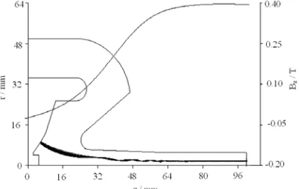
All the gyro-devices, including small-orbit gyrotron [1–4], large-orbit gyrotron [5–7] and peniotron [8–11], use interaction between the transverse energy of cyclotron electron beam and transverse electric field of electromagnetic mode. Peniotrons have been proven capable of achieving high conversion efficiency [8]. However, the experimental progress of them was much lower than expected, and the main technology obstacle is the difficulty in the formation and modulation of high-quality axis-encircling electron beam. We have reported an 8 mm-band 3rd harmonic peniotron in previous studies [9, 10]. In this paper, a corresponding permanent magnet system and large-orbit electron gun are designed, which can meet the special requirements of the beam-wave interaction in the above mentioned peniotron. The main advantages of such a peniotron are its compact size and low cost, which can meet the needs of vehicle, airborne and other mobile devices. The prominent feature of this magnetic system is its very short transition zone. Although a short transition zone helps reduce the volume, it also makes the electron gun design a challenge. Under the permanent magnetic condition, an axis-encircling electron beam with axial velocity spread 4.48%, guiding center deviation ratio 6.97% and high velocity ratio 2.03 is obtained. Finally, the electron gun with a gradually reversed magnetic field is used to drive the 3rd harmonic peniotron. An output power of 35.4 kW is obtained, and the device efficiency is up to 56.0%.
2. THE PERMANENT MAGNET SYSTEM
The gyro-devices typically operate in strong magnetic field as the operating frequency and electron cyclotron frequency required should be close to each other. In general, the strong magnetic field is provided by a large, bulky and expensive superconducting magnetic system. In plasma heating and other large systems [3, 4], the magnetic system has no problem, but for vehicle systems and small mobile devices it will become a serious obstacle. However, compared with the superconducting magnetic
Received 21 August 2015, Accepted 18 October 2015, Scheduled 23 October 2015
* Corresponding author: Xinhui Wu ([email protected]).
1 School of Science, Southwest Petroleum University, Chengdu, Sichuan, P. R. China.2 School of Physical Electronics, University of
The typical cross-sectional configuration of the 3rd harmonic peniotron is shown in Figure 2, and its basic characteristics are listed in Table 1, from which we propose the following requirements for the permanent magnet system. Firstly, the homogeneous magnetic amplitude of the beam-wave interaction region is about B0 = 0.396 T. Meanwhile, it should have 5% adjustable. Secondly, to facilitate the sufficient beam-wave interaction in the resonator, and the homogeneous length should be 40–50 mm. Thirdly, to produce the required axis-encircling electron beam, the mutual adaption between the electron gun and the magnetic distribution of the cathode reversal region is very important. Fourthly, to facilitate the gun arrangement, the magnetic shielding can be added to the gun area.
The magnet design should be compact enough, and the magnet size, weight and cost should be taken into account. The permanent magnet system consists of permanent magnets, adjustable coils, and pole pieces. Its cross-sectional diagram is shown in Figure 3. Here, the NdFeB-32-MGOe is chosen as the permanent magnet material to provide the main field as it has good performance of magnetism, good mechanics, and its resources are rich enough compared with its predecessors [16]. The weight of the permanent magnets is about 26.6 kg, inner radius 120 mm, outer radius 230 mm and width 55 mm. The material of pole piece is A3 steel, and its total weight is 40 kg. An adjustable 8 kg magnet wire package is laid in the center of the magnet system to fine-tune the magnitude and the gradient of the field in the interaction region, which can strengthen the beam-wave interaction further. Coupled with
Figure 1. The axial magnetic field distribution of peniotron.
(a) (b)
Figure 2. The cross sections of four-slotted peniotron model: (a) transverse and (b) longitudinal.
Table 1. Parameters of the 8 mm 3rd harmonic peniotron.
Voltage U/kV 43.5 Current I/A 1.45 Magnetic field B0/T 0.396
Frequency f/GHz 30 Slot number N 4 Working mode 2π
Figure 3. The cross-sectional configuration of the magnet system.
Figure 4. The magnetic field distribution along the system axis.
Figure 5. The gun structure of the 3rd harmonic peniotron (the gun region).
the other structural piece, the total weight of the magnetic system is within 100 kg. The axial length of the whole magnetic system is 500 mm, and the diameter is 300 mm. Obviously, its structure is very compact.
Figure 4 shows the axial magnetic field distribution along the system axis, from which we can see that the magnitude of the magnetic field uniform region is 0.396 T, and the length is about 50 mm. Within this range, the magnetic field inhomogeneity is less than 0.5%. Note that the distance from the reversal point to the entrance of the magnetic field uniform zone is only 70 mm, and it is a major problem for the electron gun design as to how to achieve axis-encircling electron beam conversion in such a short distance.
3. THE LARGE-ORBIT ELECTRON GUN
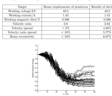
The results of the electron gun and the basic requirements of the 3rd harmonic peniotron are shown in Table 2. As can be seen by comparson, the set of beam parameters fully meet the requirements of the 3rd permanent magnet packaging peniotron.
According to the simulation of large signal code of peniotron [10], an output power of 35.4 kW is obtained, and the device efficiency is up to 56.0% driven by the above-mentioned electron gun. Figure 6 indicates the distribution of relative electron beam energy along the z-axis. As shown in the figure, the energy of all electrons decelerates from an overall perspective (the electron energy at the outlet is smaller than that at the inlet), and the beam’s remaining energy is relatively concentrated after through the interaction region, which is easy to collect by depressing collector further.
Table 2. Comparison of beam parameters between electron gun and peniotron.
Target Beam requirements of peniotron Results of electron gun
Working voltage/kV 43.5 43.5
Working current/A 1.45 1.45
Working magnetic filed/T 0.396 0.396
Velocity ratio 2.0 2.03
Velocity spread <5% 4.48%
Velocity ratio spread <10% 5.77%
Beam eccentricity <10% 6.97%
0 10 20 30 40 50 60
0.2 0.3 0.4 0.5 0.6 0.7 0.8 0.9 1 1.1 1.2
z / mm
R
e
la
ti
v
e
El
e
c
tr
o
n
En
e
rg
y
Figure 7. Beam performance vs. Δz. Figure 8. Device performance vs. Δz.
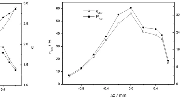
In the regulation of the electron gun we found that the electron beam quality is very sensitive to the relative position between the electrode system and magnetic system Δz, so it is bound to influence the performance of peniotron. The variation of the beam performance and device performance versus Δz are summarized in Figure 7 and Figure 8, respectively. In fact, the translation of the magnetic system relative to the electrode is equivalent to the change of the magnetic field strength Bk of the cathode region. As can be seen from the two figures, the cathode magnetic field Bk increases as Δz increases from −1 mm to 0.6 mm (the magnetic system pan right), and the velocity ratio is increasing, but the velocity ratio spread and velocity spread increase at first and then decrease, so do the output power and device efficiency. This is because the output power and efficiency are not determined by the velocity ratio uniquely, and they also have relationship with the degree of velocity spread and the guiding centre deviation ratio, which confirms our previous conclusion once again [10]. Specially, when the magnitude of magnetic field in cathode region increases to a certain value, that is, when the magnetic system shifts to the right to a certain extent (Δz≥0.4 mm), some electrons will reverse back to bombard the cathode. The more rightward shifting is, the more inversion electrons are. When the magnetic system shifts to the right of 0.8 mm, all the electrons will reverse back, and there will be no electrons participating in the energy exchange from the beam-wave interaction, which is also a major factor leading to a sharp reduction of the device efficiency. Taking all these factors into consideration, the position Δz= 0 mm is chosen in the design, and then the device efficiency and power are as high as 56.0% and 35.4 kW, respectively, which reach the maximum.
Figure 9 shows the distribution of relative electron energy at Δz=−0.6 mm. Although the velocity spread of the electron beam is small, the large beam eccentricity and small velocity ratio (i.e., small beam transverse energy) result in a relatively small energy exchange. Thus its efficiency and output power are relatively low. The distribution of relative electron energy at Δz = 0.6 mm is depicted in Figure 10. The remaining energy of the electron beam is not focused for the large beam eccentricity, and there is a small part of the electrons basically not producing any energy. Although the velocity ratio is large enough (i.e., beam transverse energy is big), there are 62% of the electron beam inversed already which are not able to participate in the energy exchange process. This is the major factor that leads to the dramatic reduction of device efficiency and output power.
collects the remaining energy of the electron beam. The permanent magnet system is under construction currently. After its completion, the 3rd harmonic peniotron with a permanent magnet system can be tested based on our host-test platform for the gyrotron.
0 10 20 30 40 50 60
0.65 0.7 0.75 0.8 0.85 0.9 0.95 1 1.05
z / mm
R e la ti v e El e c tr o n En e rg y
Figure 9. Distribution of relative electron energy at Δz=−0.6 mm.
0 10 20 30 40 50 60
0.2 0.3 0.4 0.5 0.6 0.7 0.8 0.9 1 1.1 1.2
z / mm
R e la ti v e E lec tr on E ner gy
Figure 10. Distribution of relative electron energy at Δz= 0.6 mm.
4. CONCLUSIONS
This paper designs a large-orbit electron gun and a corresponding permanent magnet system of the 3rd harmonic peniotron, in which the existing conditions of magnet and feasibility of the technology are considered. A novel axis-encircling electron beam with axial velocity spread 4.48%, guiding centre deviation ratio 6.97% and high velocity ratio 2.03 is obtained, which can drive the 3rd harmonic peniotron. A high device efficiency 56.0% with output power 35.4 kW is obtained driven by the electron gun, which lays a good foundation for the development of permanent magnet packaging peniotron test systems. Such a peniotron with a permanent magnet system has two significant advantages. One is that the electron gun uses a gradual reversed magnetic field to form the axis-encircling beam instead of an abrupt field. The other is its much more compact size and lower cost. A particular note is that the relative axial position between the electrode system and magnet system has a great influence on the device performance, which needs careful and precise adjustment in the experiment.
ACKNOWLEDGMENT
This work was supported by the Department of Sichuan Provincial Education under Grant No. 14ZA0051, the School Foundation of Southwest Petroleum University under Grant No. 344 and No. 2012XJZ032.
REFERENCES
1. Singh, G. and B. N. N. Basu, “Modal analysis of azimuthally periodic vane-loaded cylindrical waveguide interaction structure for gyro-TWT,” Progress In Electromagnetics Research, Vol. 70, 175–189, 2007.
2. Kumar, N., U. Singh, A. Kumar, H. Khatun, T. P. Singh, and A. K. Sinha, “Design of 35 GHz Gyrotron for material processing applications,”Progress In Electromagnetics Research B, Vol. 27, 273–288, 2011.
3. Kesari, V., “Beam-absent analysis of disc-loaded-coaxial waveguide for application in gyro-TWT (Part-1),” Progress In Electromagnetics Research, Vol. 109, 211–227, 2010.
4. Kesari, V., “Beam-present analysis of disc-loaded-coaxial waveguide for its application in gyro-TWT (Part-2),” Progress In Electromagnetics Research, Vol. 109, 229–243, 2010.
5. Idehara, T., I. Ogawa, S. Mitsudo, Y. Iwata, S. Watanabe, Y. Itakura, K. Ohashi, H. Kobayashi, T. Yokoyama, V. Zapevalov, M. Glyavin, A. Kuftin, O. Malygin, and S. Sabchevski, “Development of a high harmonic gyrotron with an axis-encircling electron beam and a permanent magnet,”
Vacuum, Vol. 77, No. 4, 539–546, 2005.
6. Glyavin, M., S. Sabchevski, and T. Idehara, “Numerical analysis of weakly relativistic large orbit gyrotron with permanent magnet system,” Int. J. Infr. Mill. Waves, Vol. 21, No. 8, 1211–1221, 2000.
7. Zapevalov, V., T. Idehara, and S. Sabchevski, “Design of a large orbit gyrotron with a permanent magnet system,”Int. J. Infr. Mill. Waves, Vol. 24, No. 3, 253–260, 2003.
8. Vitello, P., “Design considerations for the gyro-peniotron oscillator,” Int. J. Infr. Mill. Waves, Vol. 8, No. 5, 487–515, 1987.
9. Zhao, X. Y., J. Y. Li, and X. H. Wu, “Theoretical design and simulation of 8 mm-band third-harmonic slotted peniotron,”Chin. J. Vacuum Sci. Tec., Vol. 31, 194–200, 2011.
10. Wu, X. H., J. Y. Li, and B. Hu, “Numerical study of an 8 mm third-harmonic peniotron with a gradual reversal of the magnetic field,”Phys. Plas., Vol. 19, 023101-1-8, 2012.
11. Song, H. and T. Mulcahy, “A large orbit electron gun design for a terahertz harmonic gyrotron,”
Journal of Electromagnetic Waves and Applications, Vol. 25, No. 10, 1437–1447, 2011.