Multiband Probe-Fed Stacked Patch Antenna for GNSS Applications
Zeheng Lai*, Jiade Yuan, Xiaojie Yang, Zhangfan Ye, and Weiqiang Chen
Abstract—A novel design of multiband probe-fed stacked patch antenna for Beidou Satellite Navigation System (BDS) and Global Position System (GPS) applications is proposed. The presented antenna covers BDS-1 L (1616±5 MHz), BDS-1 S (2492±5 MHz), BDS-2 B1 (1561±5 MHz) and GPS L1 (1575±5 MHz) frequency bands. Excellent high port isolation and Circular Polarized (CP) performance are achieved by introducing four metallized holes which are strictly symmetrical about the centre of the patch antenna. The proposed antenna is fabricated, and its performance is verified in measurement.
1. INTRODUCTION
Nowadays, Global Navigation Satellite System (GNSS) is intensively used both in civilian and military areas. In the future, satellite navigation receivers will use different satellite navigation systems to improve positioning accuracy and reliability. Therefore, multiband GNSS antennas are urgently demanded for GNSS receivers. Recently, microstrip antenna has been widely used in GNSS for lots of advantages including light weight, low profile, easy circuit integration, low fabrication cost and ease of fabrication [1]. Availability of limited space on GNSS terminals is a major challenge for the antenna design. Moreover, embedding multiband antennas to cover multi frequency bands give rise to the problem of port isolation. In order to overcome these problems, a large number of studies for GNSS antennas have been reported in the literature [2–6]. Part of GNSS antennas can only cover a single band [2] or operate in a single mode [3]. A multi-band, multi-port antenna includes at least one patch radiating element and at least one ring radiating element is proposed in [4].
A design of single-feed stacked patch triple-band dual-polarized antenna for GPSL1, GPSL2 and GSM 1800 band is presented in [5]. The antenna in [5] supports right-hand circular polarized (RHCP) at GPS L1 band and linear polarization (LP) at GSM 1800 band. However, the antenna does not support left-hand circular polarized (LHCP) and can’t be used in the special field such as BDS-1. The antenna proposed in [6] is able to operate at GPS, GLONASS, and BDS-2 bands. However, its size is rather large for some applications, and the air gap between the patches increases the fabrication complexity. In addition, the uplink L-band and downlink S-band for BDS-1 have not been covered. An antenna which operates at the satellite navigation frequency bands including GPS, GLONASS, BDS-1, and BDS-2 is presented in [7]. The antenna has four stacked annular patches to achieve multiband operation and Quadrature phase feed network to ensure CP radiation and desirable port isolation. However, the antenna usually needs a complex feed network which is hard to fabricate and the gain of the antenna would decline due to the transmission line loss. Antennas proposed in [8, 9] have good port isolation, while its size is rather large for compact handheld terminals and the special design increases the fabrication complexity.
In this paper, a novel design of multiband probe-fed stacked patch antenna for the operation in BDS-1 L, BDS-BDS-1 S, BDS-2 BBDS-1 and GPS L1 band is presented. The proposed antenna has achieved excellent high port isolation and CP performance by introducing four symmetrical distribution metallized holes. The paper presents the antenna configuration and parametric studies, and compares measured results with simulated. Finally, a brief conclusion is provided.
Received 28 September 2014, Accepted 6 November 2014, Scheduled 7 November 2014
* Corresponding author: Zeheng Lai (lzh fzu@sina.cn).
2. ANTENNA DESIGN
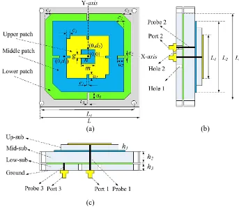
The configuration of the proposed antenna is shown in Figure 1. The antenna is made up of three stacked radiating elements. The upper-patch and the middle-patch are etched on Rogers Ro4533 with thickness ofh1= 1.6 mm andh2= 3.2 mm, respectively. The relative permittivity isεr= 3.45 with loss tangent tanδ= 0.022. The lower-patch is etched on Rogers Ro4725 with thickness ofh3 = 1.6 mm and relative permittivity εr = 2.55 with loss tangent tanδ = 0.02. The lower patch is used for producing the BDS-1 L band, the middle patch for the GPS L1 and BDS-2 B1 band, and the upper patch for the BDS-1 S band. The compact U-shaped slotted upper patch is applied and fed on the patch centre, as shown in Figure 1(a). A slot is used in the lower and middle patch, it lengthens the surface current path of the antenna and thus lowers the resonant frequency by lowering the physical length of the patch. The lower and middle square patches are corner truncated to generate the CP broadside radiation patterns. The feed probe for the middle patch pass through a metallized hole between the lower patch and the middle patch for shielding the electromagnetic radiation produced by the feed probe and reducing the influence on the lower patch antenna, especially for port isolation. In this case, a metallized hole can be used to improve port isolation. However, the antenna structure is asymmetric after introducing one metallized holes, and so that it would have much impact on the CP performance of the proposed antenna. A conclusion can be drawn that four symmetrical metallized holes are conductive to improving CP performance through simulations and measurements. In order to improve the CP performance, four metallized holes which are symmetric about the centre of the proposed antenna are introduced, as shown in Figure 1(a). The electromagnetic simulation software is used to design and optimize the geometric parameters. The square patch is L1 = 28.8 mm for the upper patch, L2 = 49.5 mm for the middle patch, L3 = 60.5 mm for the lower patch, and the ground plane size is 68×68 mm2. Other optimized parameters arec1 = 1.62 mm,c2 = 4.5 mm,c3= 4 mm, c4 = 2 mm,a2= 2 mm, a3 = 2 mm,e2= 1 mm, e3= 1 mm, d2 = 9 mm,d3= 15.6 mm, m= 9.2 mm,n= 8.8 mm, g= 2.8 mm, as shown in Figure 1.
(a) (b)
(c)
3. RESULTS AND DISCUSSION
The proposed antenna prototype is fabricated as shown in Figure 2. TheS-parameters of the fabricated prototype are measured with an Agilent E5071C network analyser. The simulated and measured results including return loss and isolation are shown in Figure 3 and a good agreement is observed. The measured −10 dB impedance bandwidth in the BDS-1 L, BDS-2 B1/GPS L1 and BDS-1 S bands are 1.60 GHz∼1.62 GHz (20 MHz) 1.54∼1.58 GHz (40 MHz) and 2.47∼2.5 GHz (30 MHz), respectively. The simulated result of S12 is less than −25.9 dB while the measured result is less than −21.3 dB at the frequency of 1.568 GHz. The simulated and measured result of S13 agrees well, as shown in Figure 3,
(a) (b)
Figure 2. Fabricated of proposed antenna. (a) Top view. (b) Bottom view.
Figure 3. Measured and simulatedS parameters of the proposed antenna.
Figure 4. Measured and simulated axial ratio of the proposed antenna.
0
30
60
90
150 180
210 240 270
300 330
Stimulated Gain Total -15
-10 -5 0
Stimulated Gain RHCP 5
Stimulated Gain LHCP Measured Gain
0
90
180
270 -20
-10 0
Stimulated Gain LHCP 10
Stimulated Gain RHCP
0 30 60 90 18 0 210 240 270 300 330 -12 -6 3
Stimulated Gain Total 0
Stimulated Gain LHCP Stimulated Gain RHCP Measured Gain 0 90 180 270 -10 -30
Stimulated Gain RHCP 10
Stimulated Gain LHCP
ϕ=0o θ=0o
(d) 0 30 60 90 210 240 270 300 330 -13 -10 0 -5
Stimulated Gain Total 5
Stimulated Gain RHCP
Stimulated Gain LHCP Measured Gain 0 90 180 270 -20 -10 0
Stimulated Gain LHCP 10
Stimulated GainR HCP
0 30 60 90 180 210 240 270 300 330 -13 0 -5
Stimulated Gain Total 5
Stimulated Gain RHCP Stimulated Gain LHCP Measured Gain 0 90 180 270 -10 0
Stimulated Gain LHCP 10
Stimulated Gain RHCP 180
ϕ=0o θ=0o
ϕ=0o (b) θ=0o
(c)
Figure 5. Measured and simulated radiation patterns in xz-plane; Simulated radiation patterns in xy-plane. (a) Radiation patterns at BDS-1 S frequency of 2491.750 MHz. (b) Radiation patterns at BDS-2 B1 frequency of 1561.098 MHz. (c) Radiation patterns at GPS L1 frequency of 1575.420 MHz. (d) Radiation patterns at BDS-1 L frequency of 1615.680 MHz.
BDS-2 B1 band of GNSS, respectively.
The radiation patterns of the proposed antenna are tested in the anechoic chamber. The measured and simulated radiation patterns in xz-plane and xy-plane at BDS-1 S frequency of 2491.750 MHz, BDS-2 B1 frequency of 1561.098 MHz, GPS L1 frequency of 1575.42 MHz and BDS-1 L frequency of 1615.68 MHz are shown in Figure 5, respectively. From Figure 5, it can be observed that the measured gain agree well with the simulated gain. The gain of the right-hand-circular polarized (RHCP) pattern is much stronger than the gain of the LHCP pattern by more than 10 dB and almost as same as the total gain in Figure 5(a), which means that low cross polarization and good circular polarization radiation patterns are excited at 2.492 GHz. Figure 5(d) shows that the antenna supports left-hand circular polarized at BDS-1 L frequency of 1615.68 MHz due to the fact that LHCP pattern is much stronger than the RHCP pattern, and the gain of LHCP is almost as same as the total gain. From Figure 5(b) and Figure 5(c), we can also observe that the proposed antenna obtains low cross polarization and excellent CP performance.
4. CONCLUSION
A novel design of multiband probe-fed stacked patch antenna for Beidou Satellite Navigation System (BDS) and Global Position System (GPS) applications is proposed. The antenna operates at four frequency bands with a desired performance through design optimization. High port isolation and CP performance with a radiation pattern are achieved by introducing four symmetry metallized holes. Both simulated and measured results demonstrate that the proposed antenna has desirable port isolation, good impedance matching and CP performance with simple methods. The proposed antenna can be applied effectively in the satellite navigation terminal products that integrate two systems, such as BDS and GPS.
ACKNOWLEDGMENT
This work was supported by the Science and Technology Development Foundation of FuZhou University (2014-XQ-36).
REFERENCES
1. Wang, Z. H., H. M. Liu, S. J. Fang, and Y. Cao, “A low-cost dual-wideband active GNSS antenna with low-angle multipath mitigation for vehicle applications,”Progress In Electromagnetics Research, Vol. 144, 281–289, 2014.
2. Chen, H. M., Y. K. Wang, Y. F. Liu, C. Y. Lin, and S. C. Pan, “Microstrip-fed circularly polarized square-ring patch antenna for GPS applications,” IEEE Trans. Antennas Propag., Vol. 57, No. 4, 1264–1267, 2009.
3. Falade, O. P., M. U. Rehman, Y. Gao, X. Chen, and C. G. Parini, “Single feed stacked circular polarized antenna for triple band GPS receivers,” IEEE Trans. Antennas Propag., Vol. 60, No. 10, 4479–4484, 2012.
4. Cheng, D., “Compact multi-band, multi-port antenna,” US Patent 7289064, Oct. 30, 2007.
5. Falade, O. P., Y. Gao, X. Chen, and C. G. Parini, “Stacked-patch dual-polarized antenna for triple-band handheld terminals,”IEEE Antennas Wirel. Propag. Lett., Vol. 12, 202–205, 2013. 6. Wang, Z. B., S. J. Fang, S. Q. Fu, and S. W. Lu, “Dual-band probe-fed stacked patch antenna for
GNSS applications,”IEEE Antennas Wirel. Propag. Lett., Vol. 8, 100–103, 2009.
7. Li, J. X., H. Y. Shi, H. Li, and A. X. Zhang, “Quad-band probe-fed stacked annular patch antenna for GNSS applications,”IEEE Antennas Wirel. Propag. Lett., Vol. 13, 372–375, 2014.