Study of Load Characteristics in Wireless Power Transfer System
with Ferrite Core
Meng Wang1, Jing Feng1, Minghui Shen2, and Yanyan Shi1, *
Abstract—For wireless power transfer via magnetic resonant coupling (MRC-WPT), magnetic coupling between resonant coils can be greatly enhanced when a ferrite core is introduced inside the coils. Based on the equivalent circuit model of wireless power transfer system, transfer characteristics of the MRC-WPT system with air resonant coils and with a ferrite core are respectively analyzed in this paper. The influence mechanism of the load on the power transfer efficiency is investigated. Also, the requirement of load for improving transfer efficiency is derived when adding the ferrite core to the system. The numerical simulation and experiment result indicate that the transmission efficiency in the MRC-WPT system with ferrite core is higher than that in the counterpart with air resonant coils in the whole transfer region when the load is larger than the maximal critical load. In addition, for different transfer distances, the system efficiency for the system using the ferrite core tends to become lower than that in the air coil system when the load is smaller than the critical load.
1. INTRODUCTION
Wireless power transfer (WPT) technology makes it possible to deliver electromagnetic energy to the load without direct wire connection. Generally, wireless power transfer in the near-field can be categorized into inductive WPT (IWPT), magnetic resonant coupling WPT (MRC-WPT) and radio wave [1]. Compared with the other two types of technology, inductive WPT has been maturely developed and utilized in many real applications [2, 3]. Since the inspiring work of Massachusetts Institute of Technology has been published in 2007, an increasing amount of research has been conducted on wireless power transfer via magnetic resonant coupling (MRC-WPT) due to its characteristics of long transfer distance, high transmission efficiency and great convenience [4–8]. For a better transfer performance, there have been extensive reports on the analysis for MRC-WPT system [9–11].
To extend the transfer distance, resonant coils with large size are used [12]. However, its application is generally restricted because of the large volume. An alternative method is the utilization of intermediate coils [13–15]. By positioning the repeater between the transmitting coil (Tx) and receiving coil (Rx), the transfer distance is increased. Nevertheless, the transmission efficiency drops rapidly when the repeater is deviated from a specific position, and it is inconvenient for practical applications to place the additional resonator in the free space between coils. High Q-factor of coils is a possible solution to increase the transfer efficiency of MRC-WPT system [16]. However, too high operating frequency will result in the instability of the system and increase the cost.
High permeability materials, such as ferrite cores, can be used to enhance the magnetic coupling between coils, and hence the transmission efficiency is increased in long distance [17–22]. In [17], a novel configuration of a magnetic resonant structure is proposed. Compared with the traditional cylindrical ferrite core, the proposed ferrite core has a smaller demagnetizing factor and an increased
Received 16 August 2018, Accepted 2 October 2018, Scheduled 14 October 2018
* Corresponding author: Yanyan Shi ([email protected]).
1 College of Electronic and Electrical Engineering, Henan Normal University, Xinxiang, Henan 453007, China. 2 Xinxiang Power
using ferrite materials. Compared with the traditional system using air core, the transfer efficiency is increased by 42% with the proposed system. To improve the misalignment tolerance of the WPT system with ferrite core and minimize the core loss, the configuration of the ferrite cores is optimized in [21]. The flux density maintains uniform, and the core loss is reduced by 39% in the optimized ferrite core compared with the uniform thickness core. In [22], the Q-factor of coils with ferrite core is calculated. It is revealed that the transfer efficiency is increased by using ferrite core with high permeability and low hysteresis loss. When the Mn-Zn ferrite core is inserted within coils, the efficiency is increased to 61.45%. These researches on the ferrite core structure, in cooperation with other technologies such as the optimization of the coil configuration technology, undoubtedly contribute to improving the power transfer efficiency of the MRC-WPT system. However, the transfer performance of the system with the ferrite core is also dependent on the load which influences the estimation and comparison of the system efficiency.
In this paper, the transfer characteristic of an MRC-WPT system with ferrite core is analyzed in detail. At the beginning, the power transmission efficiencies of the system with air resonant coils and with a ferrite core are calculated respectively based on the equivalent circuit model of MRC-WPT system. The requirement of the load to increase the efficiency is analyzed when adding the ferrite core to the system. After that, the mutual inductance and the transmission efficiency under different loads for the two different systems are simulated. Then, experiments are carried out to validate the theoretical analysis. Finally, concluding remarks are drawn.
2. EQUIVALENT CIRCUIT MODEL FOR MRC-WPT
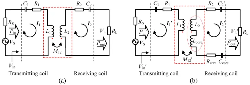
The equivalent circuit model of the MRC-WPT system with air resonant coils and with a ferrite core is illustrated in Fig. 1. Both transmitting coil and receiving coil can be described as the self-inductance (L1,L2) and the resistance of the resonant coils (R1, R2) connected in series. C1, C2 and C2 are the
compensated capacitance of the transmitting coil and receiving coil. I1,I1,I2 and I2 are the currents
flowing in the transmitting loop and receiving loop, respectively. VS and RS indicate the voltage and internal resistance of the power source. RL is the load. VL and VL are the voltage across the load.
M12is the mutual inductance betweenL1 andL2, as shown in Fig. 1(a). The ferrite core provides a low
reluctance path for the magnetic flux, which is denoted byCcore,Lcore andRcoreconnected in series, as shown in Fig. 1(b). Ccore can be ignored compared withC2 [23]. M12 is the mutual inductance between
L1 andL2+Lcore.
When the operating frequency isω, the equivalent circuit of the system with air resonant coils and with a ferrite core can be expressed as:
Vin =Z11I1−jωM12I2
Z22I2−jωM12I1= 0 ,
(1)
Vin =Z11I1−jωM12 I2
Z22 I2−jωM12 I1= 0
, (2)
where Vin and Vin are the voltage of the input port respectively, Z11 = R1 + j(ωL1 − 1/ωC1),
Z22=RL+R2+j(ωL2−1/ωC2), andZ22 =RL+Rcore+R2+j(ωL2+ωLcore−1/ωC2).
(b) (a)
Figure 1. Equivalent circuit model of MRC-WPT system. (a) System with air resonant coils. (b) System with a ferrite core.
by using Eq. (1) as [24]:
⎧ ⎪ ⎪ ⎪ ⎪ ⎨ ⎪ ⎪ ⎪ ⎪ ⎩
Pin= Re
Z11Z22+ (ωM12)2
Z22 I 2 1
Pout= Re
RL(ωM12)2
Z2 22
I2 1
, (3)
Similar to the system with air resonant coils, the input power Pin and output power Pout of the system with the ferrite core can be written using Eq. (2) as:
⎧ ⎪ ⎪ ⎪ ⎪ ⎨ ⎪ ⎪ ⎪ ⎪ ⎩ P in= Re
Z11Z22 + (ωM12 ) 2
Z
22
I2 1
P
out= Re
RL(ωM12 ) 2
Z2 22
I2 1
. (4)
When the system with air core is tuned at the resonant frequencyω0, the transfer efficiency of the
MRC-WPT systemη can be expressed by using Eq. (3) as:
η= RL(ω0M12)
2
R1(R2+RL)2+ (R2+RL) (ω0M12)2
, (5)
whereω0= 1/(L1C1)0.5 = 1/(L2C2)0.5.
According to Eq. (4), the transfer efficiency of the MRC-WPT system with the ferrite coreη can be calculated by
η = RL(ω0M12 ) 2
R1(R2+Rcore+RL)2+ (R2+Rcore+RL) (ω0M12 )2
, (6)
whereω0= 1/(L1C1)0.5 = 1/(L2+Lcore)C2)0.5.
When the ferrite core is inserted within the resonant coil, the ferrite core will be magnetized, and the magnetic field through the coil is intensified. Thus, the mutual inductance between the coils with the ferrite core is larger than that between the air resonant coils, i.e., M12 > M12 in this paper [25].
R∗L= √ K
K2−1
R2
core K2−1 +
Rcore(ω0M12)2
R1
+ Rcore
K2−1 −R2, (9)
whereR∗L is the critical load andK =M12 /M12.
From Eq. (9), it can be seen that the critical load is different for various transfer distances. For a fixed transfer distance, the transfer efficiency of the MRC-WPT system with the ferrite core would be higher than that with the air core when the load is larger than the critical load R∗L. To make the efficiency of the MRC-WPT system with ferrite core keep higher than that in the counterpart with air resonant coils in the whole transfer region, the load of the system with the ferrite core must be bigger than the maximal critical load which is denoted byRmax
L . It should be noted thatK is larger than one
in Eq. (9).
3. NUMERICAL SIMULATION
For validation, simulation has been carried out using Maxwell, which is a simulation software package based on the finite-element method. In the work, the resonant frequency is set to 0.8 MHz. The cylindrical ferrite core is applied, and its configuration is illustrated in Fig. 2. All coils are constructed with 1.4-mm-diameter copper wire, and the parameters of the simulation are shown in Table 1.
Figure 2. Configuration of the cylindrical ferrite core, wherer= 50 mm and L= 60 mm.
Table 1. Parameters of the simulation.
Parameters System with air resonant coils System with the ferrite core
Radius of Tx r1= 50 mm r1= 50 mm
Radius of Rx r2= 50 mm r2= 50 mm
Number of turns of Tx n1 = 20 n1 = 20
Number of turns of Rx n2 = 10 n2 = 10
Pitch between turns of Tx p1 = 1.5 mm p1 = 1.5 mm
Pitch between turns of Rx p2 = 1.5 mm p2 = 1.5 mm
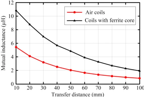
Figure 3. Simulated mutual inductance versus the transfer distance for the air resonant coils and the coils with the ferrite core.
Figure 4. Core loss versus time for the ferrite core.
distance increases. However, the mutual inductance of the coils with the ferrite core is generally larger than that of the air resonant coils. This is because the magnetic field through the coil is enhanced due to the magnetization of the ferrite core. When the transfer distances are 10 mm and 100 mm, the mutual inductances for the coils without ferrite core are 5.43µH and 0.82µH, whereas the values are 10.83µH and 1.92µH in the coils with ferrite core. The mutual inductance is improved by 99% and 134% respectively compared with the air resonant coils. In the whole transfer region, the average mutual inductance for the coils with ferrite core is higher than that for the air resonant coils by 128%.
To obtain the equivalent resistance of the ferrite core Rcore, the ferrite core loss is analyzed in Maxwell, a simulation software package based on the finite-element method, and the result is shown in Fig. 4. In the work, the flowing in the receiving loop is 10 mA, and the driving power is 52 mW. From Fig. 4, it can be seen that the average core lossPav is 1.31 mW. Based on the analysis in [26], the equivalent resistance of the ferrite core is calculated to be Rcore= 13.1 Ω.
According to Eq. (9), the mutual inductance shown in Fig. 3 and the equivalent resistance of the ferrite core, the critical load of the MRC-WPT system with the ferrite core for different transfer distances can be calculated which is illustrated in Table 2. It can be seen from Table 2 that the critical load decreases with the increase in the transfer distance. To improve the efficiency, the load of the system with the ferrite core must be larger than 115.40 Ω, i.e.,RmaxL = 115.40 Ω in this paper.
Figure 5 compares the efficiency of the system with air core and with ferrite core for different loads.
Table 2. Critical loads for different transfer distances.
Distance (mm) M12 (µH) M12 (µH) K=M12 /M12 R∗L (Ω)
10 5.43 10.83 2.00 115.40
20 4.08 8.74 2.14 84.97
30 3.16 6.98 2.21 65.42
40 2.50 5.68 2.27 51.58
50 2.01 4.84 2.41 40.87
60 1.65 3.89 2.36 34.08
70 1.36 3.24 2.38 28.31
80 1.14 2.68 2.35 24.21
90 0.96 2.25 2.34 20.83
(b) (a)
Figure 5. Power transfer efficiency versus the transfer distance for the system with air core and with ferrite core. (a) Load is smaller than the maximal critical load. (b) Load is larger than the maximal critical load.
As shown in Fig. 5, the efficiency decreases with the increase in the transfer distance for the two different systems. The efficiency of the system with the ferrite core is lower than that of the system with air core when the transfer distance is within 43 mm in the case of RL = 50 Ω. As the load decreases to 20 Ω, the efficiency for the system with the ferrite core is higher only at the distance of 100 mm than the system with air resonant coils, as shown in Fig. 5(a). Moreover, it can be observed from Fig. 5(b) that the transmission efficiency is significantly improved in the whole transfer region when the load is larger than the maximal critical load RmaxL , which is well consistent with Table 2.
4. EXPERIMENTAL VALIDATION
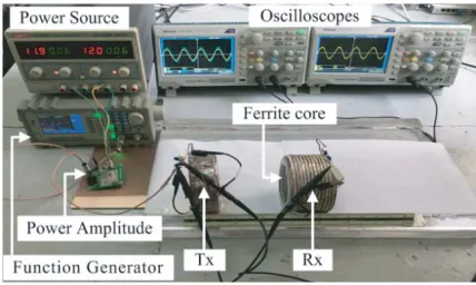
An experimental prototype of MRC-WPT system is established to validate the performance of the system with different loads, as given in Fig. 6. The transmitting coil is connected in series to the power amplitude whose input signal is supplied by the function generator. The receiving coil is wound on a cylindrical ferrite core and is connected with the load. Compensated capacitances are used for the magnetic resonance. The experimental parameters of the coils and the ferrite core are the same as that in the simulation. Fig. 7 shows the variations in the mutual inductance versus the transfer distance for the coils with air core and with ferrite core.
As demonstrated in Fig. 7, the mutual inductance decreases as the transfer distance increases for different types of coils configurations. Comparing Fig. 7 with Fig. 3, an excellent agreement can be
observed between the measured and simulated results. The average mutual inductance is improved by 121% when the ferrite core is introduced.
Figure 8 shows a comparison of the efficiencies for the system with air core and with ferrite core. As illustrated in Fig. 8(a), when the load is set to 50 Ω the efficiency of the system using the ferrite core is lower within the transfer distance of 40 mm. In the case of RL= 20 Ω, the transmission efficiency of the system with the ferrite core is slightly higher than that of the system with air core at the distance
Figure 7. Measured mutual inductance versus the transfer distance for the air resonant coils and the coils with the ferrite core.
(b) (a)
Figure 8. Measured efficiency for the system with air core and with ferrite core. (a) Load is smaller than the maximal critical load. (b) Load is larger than the maximal critical load.
(b) (a)
5. CONCLUSION
According to the equivalent circuit model of the MRC-WPT system, the transmission efficiencies of the system with air resonant coils and with ferrite core are calculated respectively in this work. The requirement of load for improving transfer efficiency is derived when the ferrite core is introduced to the system. The different systems with various loads are simulated and tested. The results indicate that the performance of the system with the ferrite core is superior to the system with an air core when the load is larger than the critical load. However, when the load is very small, the MRC-WPT system with air core is a better alternative. This research provides a guideline for choice of different MRC-WPT systems in various load conditions.
ACKNOWLEDGMENT
This work was supported by the Key Science and Technology Project of Henan Province of China under Grant No. 182102210080 and the Foundation for University Key Young Teacher by Henan Province of China under Grant No. 2017GGJS040.
REFERENCES
1. Shinohara, N., “The wireless power transmission: inductive coupling, radio wave, and resonance coupling,”Wiley Interdisciplinary Reviews: Energy and Environment, Vol. 1, 337–346, 2012. 2. Parise, M. and G. Antonini, “On the inductive coupling between two parallel thin-wire circular
loop antennas,”IEEE Transactions on Electromagnetic Compatibility, Vol. 1, 1865–1872, 2018. 3. Casanova, J. J., Z. N. Low, and J. Lin, “A loosely coupled planar wireless power system for multiple
receivers,”IEEE Transactions on Industrial Electronics, Vol. 56, 3060–3068, 2009.
4. Jiang, C., K. T. Chau, W. Han, and W. Liu, “Development of multilayer rectangular coils for multiple-receiver multiple-frequency wireless power transfer,” Progress In Electromagnetics Research, Vol. 163, 15–24, 2018.
5. Kim, J. G., G. Wei, M. H. Kim, J. Y. Jong, and C. Zhu, “A comprehensive study on composite resonant circuit-based wireless power transfer systems,”IEEE Trans. Ind. Electron., Vol. 65, No. 6, 4670–4680, 2018.
6. Wang, M., J. Feng, Y. Fan, M. Shen, J. Liang, and Y. Shi, “A novel planar wireless power transfer system with distance-insensitive characteristics,” Progress In Electromagnetics Research Letters, Vol. 76, 13–19, 2018.
7. Li, C. J. and H. Ling, “Investigation of wireless power transfer using planarized, capacitor-loaded coupled loops,”Progress In Electromagnetics Research, Vol. 148, 223–231, 2014.
8. Fan, Y., L. Li, S. Yu, C. Zhu, and C. H. Liang, “Experimental study of efficient wireless power transfer system integrating with highly sub-wavelength metamaterials,” Progress In Electromagnetics Research, Vol. 141, 769–784, 2013.
10. Zhang, J., X. Yuan, C. Wang, and Y. He, “Comparative analysis of two-coil and three-coil structures for wireless power transfer,”IEEE Trans. Power Electron., Vol. 32, No. 1, 341–352, 2017.
11. Kim, J., W. S. Choi, and J. Jeong, “Loop switching technique for wireless power transfer using magnetic resonance coupling,” Progress In Electromagnetics Research, Vol. 138, 197–209, 2013. 12. Lee, S. B., S. Ahn, and I. G. Jang, “Simulation-based feasibility study on the wireless charging
railway system with a ferriteless primary module,” IEEE Trans. Veh. Technol., Vol. 64, No. 2, 1004–1010, 2017.
13. Tran, D. H., V. B. Vu, and W. Choi, “Design of a high-efficiency wireless power transfer system with intermediate coils for the On-Board chargers of electric vehicles,” IEEE Trans. Power Electron., Vol. 33, No. 1, 175–187, 2018.
14. Kong, S., et al., “An investigation of electromagnetic radiated emission and interference from multi-coil wireless power transfer systems using resonant magnetic field coupling,”IEEE Trans. on Micro. Theory Techn., Vol. 63, No. 3, 833–846, 2015.
15. Liu, X. C. and G. F. Wang, “A novel wireless power transfer system with double intermediate resonant coils,”IEEE Trans. Ind. Electron., Vol. 63, No. 4, 2174–2180, 2016.
16. Hu, H. and S. V. Georgakopoulos, “Multiband and broadband wireless power transfer systems using the conformal strongly coupled magnetic resonance method,” IEEE Trans. Ind. Electron., Vol. 64, No. 5, 3595–3607, 2017.
17. Wang, M., J. Feng, Y. Shi, and M. Shen, “Demagnetization weakening and magnetic field concentration with ferrite core characterization for efficient wireless power transfer,”IEEE Trans. Ind. Electron., to be published. DOI 10.1109/TIE.2018.2840485.
18. Zhang, W., C. J. White, M. A. Abraham, and C. C. Mi, “Loosely coupled transformer structure and interoperability study for EV wireless charging systems,” IEEE Trans. Power Electron., Vol. 30, No. 11, 6356–6367, 2015.
19. Wang, S., D. G. Dorrell, Y. Guo, and M. F. Hsieh, “Inductive charging coupler with assistive coils,”
IEEE Trans. Magn., Vol. 52, No. 7, 1–4, 2016.
20. Antalunai, S., C. Thongsopa, and T. Thosdeekoraphat, “An increasing the power transmission efficiency of flat spiral coils by using ferrite materials for wireless power transfer applications,”
International Conference on Electrical Engineering/electronics, 1–4, Nakhon Ratchasima,
Thailand, 2014.
21. Mohammad, M., S. Choi, Z. Islam, S. Kwak, and J. Baek, “Core design and optimization for better misalignment tolerance and higher range of wireless charging of PHEV,” IEEE Trans. on Transport. Electrific., Vol. 3, No. 2, 445–453, 2017.
22. Ding, W. and X. Wang, “Magnetically coupled resonant using Mn-Zn ferrite for wireless power transfer,”15th International Conference on Electronic Packaging Technology, 1561–1564, Chengdu, China, 2014.
23. Mohammad, M., S. Kwak, and S. Choi, “Core design for better misalignment tolerance and higher range of wireless charging for HEV,”Applied Power Electronics Conference and Exposition (APEC), 1748–1755, Long Beach, CA, USA, 2016.
24. Huang, R., B. Zhang, D. Qiu, and Y. Zhang, “Frequency splitting phenomena of magnetic resonant coupling wireless power transfer,” IEEE Trans. Magn., Vol. 50, No. 11, 1–4, 2014.
25. Theilmann, P. T. and P. M. Asbeck, “An analytical model for inductively coupled implantable biomedical devices with ferrite rods,” IEEE Trans. Biomed. Circuits Syst., Vol. 3, No. 1, 43–52, 2009.