Scholarship@Western
Scholarship@Western
Electronic Thesis and Dissertation Repository
9-23-2016 12:00 AM
Enhancing the Seismic Performance of Steel Structures Utilizing
Enhancing the Seismic Performance of Steel Structures Utilizing
Superelastic Shape Memory Alloys
Superelastic Shape Memory Alloys
Papia SultanaThe University of Western Ontario
Supervisor
Maged A. Youssef
The University of Western Ontario
Graduate Program in Civil and Environmental Engineering
A thesis submitted in partial fulfillment of the requirements for the degree in Doctor of Philosophy
© Papia Sultana 2016
Follow this and additional works at: https://ir.lib.uwo.ca/etd Part of the Structural Engineering Commons
Recommended Citation Recommended Citation
Sultana, Papia, "Enhancing the Seismic Performance of Steel Structures Utilizing Superelastic Shape Memory Alloys" (2016). Electronic Thesis and Dissertation Repository. 4171.
https://ir.lib.uwo.ca/etd/4171
This Dissertation/Thesis is brought to you for free and open access by Scholarship@Western. It has been accepted for inclusion in Electronic Thesis and Dissertation Repository by an authorized administrator of
ii
ABSTRACT
Although conventional earthquake-resisting structural systems provide the life safety level
during earthquakes, they experience significant structural damage when exposed to strong
ground shaking that render structural retrofitting as uneconomical. Superelastic shape
memory alloys (SMAs) can be used in steel structures to reduce the residual
deformations due to their recentering capability, which can facilitate post-seismic
retrofitting. The primary aim of this thesis is to enhance the seismic performance of both
regular and modular steel structures using certain amount of superelastic SMAs material in
terms of maximum inter-storey drift, residual drift, and damage scheme.
First, a simplified method based on pushover analysis is proposed to identify the severely
damaged floor of a typical SMRF. It was validated with the studies by other researchers.
Three and ten-storey SMRFs are considered to further validate the method. The predicted
location of damage for the SMRFs using this method is compared to the results of static
pushover and nonlinear dynamic analyses. The method accurately identified the severely
damaged floors of SMRFs.
The proposed simplified method as well as incremental dynamic analysis is then utilized
to determine the best locations of SMA connections to improve the seismic performance
of SMRFs. Six different SMA frames are examined using nonlinear dynamic analyses.
Among all SMA frames, the frame using SMA connections at the critical first and fourth
iii
The seismic performance of modular steel braced frames (MSBFs) is significantly different
from regular steel braced frames because of their unique detailing and construction
procedure. An analytical model that can accurately predict the seismic behaviour of MSBFs
equipped with buckling restrained SMA braces is first developed. This model is then
implemented to identify the locations of SMA braces to improve the seismic performance
of MSBFs. The study highlighted the need to use SMA braces at all floors.
The study also examines the seismic performance of MSBFs utilizing superelastic SMA
bolts at the vertical connections between the modules. It was observed that the seismic
performance of a MSBF can be improved by using SMA connections at the right locations.
Keywords: Seismic performance, Steel moment resisting frames, Maximum inter-storey
drift, Maximum residual inter-storey drift, Incremental dynamic analysis. Shape memory
iv
COPYRIGHT AND CO-AUTHORSHIP
This doctoral thesis is prepared according to the regulations for an integrated-article format
thesis stipulated by the faculty of Graduate and Post Doctoral Studies at the Western
University. All the design and analytical works were conducted by the author of this thesis
under the supervision of Dr. Maged A. Youssef. Major portions of the work outlined in this
thesis have been published or are under review for possible publication in peer-reviewed
technical journals and conferences. The author wrote the initial drafts of the manuscripts,
while her research advisors, Maged A. Youssef, contributed to the final versions of the
manuscripts. The publications are as follow:
REFERRED JOURNAL PUBLICATIONS
P.Sultana, M.A. Youssef, “Seismic performance of steel moment resisting frames utilizing
superelastic shape memory alloys”, Journal of Constructional Steel Research, 2016,
Vol.125, 2016 pp. 239–251
P.Sultana, M.A. Youssef, “Prediction of local seismic damage in steel moment resisting
frames”, Journal of Constructional Steel Research, 2016,Vol.122, pp.122–137
P.Sultana, M.A. Youssef, “Seismic performance of modular steel frames equipped with
shape memory alloy braces”, in review, Journal of Constructional Steel Research, 2016.
P.Sultana, M.A. Youssef, “Seismic performance of modular steel braced frames utilizing
v
REFERRED CONFERENCE PROCEEDINGS
P.Sultana, M.A.Youssef, “ Seismic performance of modular steel frames equipped with
shape memory alloy braces”, Proceedings of 5th International Structural Specialty
Conference, CSCE, London, ON, 2016, paper no-834.
P. Sultana, M.A. Youssef, “Variations of maximum inter-storey drift for steel moment
resisting frames considering the horizontal and vertical seismic components”, Proceedings
of 5th International Conference on Performance, Protection and Strengthening of Structures
vi
DEDICATION
I dedicate this thesis to my parents, Mosleh Uddin Ahmed and Hasna Banu who have
always been a great encouragement for this great achievement, and to my husband for his
vii
ACKNOWLODGEMENT
First and foremost, I would like to thank my supervisor Dr. Maged A. Youssef. It has been
an honor to be his Ph.D student. I admire his wealth of knowledge, professionalism and
dedication to the excellence. I appreciate all his continuous advice, guidance and
encouragement throughout this research. Without his help, the thesis could not be
completed.
I gratefully acknowledge the funding from the Western University, Natural Science and
Engineering Research Council of Canada (NSERC), Ontario Ministry of Training,
Colleges and Universities through OGS scholarships, Julie Lassonde Scholarship that made
my Ph.D. work possible.
Lastly, I would like to thank my parents who supported me in all my pursuits, my sister
who is always there for me when I need her the most. Finally, to my husband, Sufian, and
lovely children Arita and Ahyan, words can not just describe how valuable your love,
viii
TABLE OF CONTENTS
ABSTRACT II
COPYRIGHT AND CO-AUTHORSHIP IV
DEDICATION VI
ACKNOWLODGEMENT VII
TABLE OF CONTENTS VIII
LIST OF TABLES XII
LIST OF FIGURES XIII
LIST OF NOTATIONS XVIII
CHAPTER 1 INTRODUCTION 1
1.1 INTRODUCTION 1
1.2 LITERATURE REVIEW 2
1.2.1 Design philosophy of steel moment resisting frames 3
1.2.2 Design philosophy of braced frames 4
1.2.3 Modular construction 5
1.2.4 Drawbacks of current design philosophy 6
1.2.5 Shape memory alloys 8
1.3 OBJECTIVES AND SCOPES 15
1.4 ORGANIZATION AND OUTLINE 17
1.4.1 Prediction of local seismic damage in steel moment resisting frames 17
1.4.2 Seismic performance of steel moment resisting frames utilizing superelastic
shape memory alloys 18
1.4.3 Seismic performance of modular steel frames equipped with shape memory
alloy braces 18
1.4.4 Seismic performance of modular steel braced frames utilizing superelastic shape
ix
1.5 REFERENCES 20
CHAPTER 2 PREDICTION OF LOCAL SEISMIC DAMAGE IN STEEL
MOMENT RESISTING FRAMES 25
2.1 INTRODUCTION 25
2.2 Proposed Method 26
2.2.1 Lateral drift (∆m) based on P-Δ effect 26
2.2.2 Lateral drift (∆m) based on storey-pushover analysis 28
2.2.3 Application of the proposed method 29
2.2.4 Vertical seismic component 30
2.3 ASPECTS OF MODELING 31
2.3.1 Failure criteria 31
2.4 VALIDATION OF THE PROPOSED METHOD 33
2.5 CASE STUDY 35
2.6 PUSHOVER ANALYSIS 37
2.7 DYNAMIC ANALYSIS 40
2.7.1 Building damage considering the horizontal components 42
2.7.2 Inter-storey drift limit at yield 48
2.7.3 Building damage considering the seismic vertical components 50
2.7.4 Deflection of beams 51
2.8 SUMMARY AND CONCLUSIONS 56
2.9 REFERENCES 58
CHAPTER 3 SEISMIC PERFORMANCE OF STEEL MOMENT RESISTING
FRAMES UTILIZING SUPERELASTIC SHAPE MEMORY ALLOYS 60
3.1 INTRODUCTION 60
3.2 STEEL MOMENT FRAME CHARACTERISTICS AND MODELING 64
3.3 PREDICTION OF THE SEVERELY DAMAGED FLOOR 65
x
3.5 SMA- STEEL FRAME CHARACTERISTICS AND MODELING 69
3.5.1 SMA connections 70
3.6 DYNAMIC ANALYSIS OF SMA-STEEL FRAMES 73
3.7 CONCLUSION 85
3.8 REFERENCES 87
CHAPTER 4 SEISMIC PERFORMANCE OF MODULAR STEEL FRAMES
EQUIPPED WITH SHAPE MEMORY ALLOY BRACES 90
4.1 INTRODUCTION 90
4.2 MODULAR STEEL BRACED FRAME 93
4.3 FINITE ELEMENT MODELING OF MSBF 95
4.3.1 Validation of FE modeling technique 96
4.4 DYNAMIC ANALYSIS OF STEEL-MSBF (FRAME 1) 99
4.4.1 Results for Frame 1 100
4.5 SMA-MSBFs CHARACTERISTICS AND MODELING 102
4.6 RESULTS FOR SMA-MSBFs 106
4.7 CONCLUSION 117
4.8 REFERENCES 120
CHAPTER 5 SEISMIC PERFORMANCE OF MODULAR STEEL BRACED FRAMES UTILIZING SUPERELASTIC SHAPE MEMORY ALLOY BOLTS IN
THE VERTICAL MODULE CONNECTIONS 123
5.1 INTRODUCTION 123
5.2 MODULAR STEEL BRACED FRAMES 126
5.3 FINITE ELEMENT MODELING OF MSBFs 129
5.3.1 Validation of FE modeling technique 130
xi
5.5 MSBF EQUIPPED WITH SMA BOLTED VERTICAL CONNECTIONS 139
5.6 CONCLUSIONS 154
5.7 REFERENCES 156
CHAPTER 6 CONCLUSIONS AND RECOMMENDATIONS 159
6.1 SUMMARY 159
6.1.1 Prediction of local seismic damage in steel moment resisting frames 159
6.1.2 Seismic performance of steel moment resisting frames utilizing superelastic
shape memory alloys 160
6.1.3 Seismic performance of modular steel frames equipped with shape memory alloy
braces
161 6.1.4 Seismic performance of Modular steel braced frame using superelastic shape
memory alloy bolts 162
6.2 MAJOR RESEARCH CONTRIBUTIONS 164
6.3 RECOMMENDATIONS FOR FURTHER STUDIES 165
APPENDIX A 167
APPENDIX B 168
xii
LIST OF TABLES
Table 2. 1: Modeling parameters for nonlinear procedures according to FEMA356 [1] 32
Table 2. 2: Section properties of Frame 3 35
Table 2. 3: Section properties of Frame 10 36
Table 2. 4: Limiting FID (%) for different floors of 3 storey frame 37
Table 2. 5: Limiting FID (%) for different floors of 10 storey frame 37
Table 2. 6: Characteristics of ground motions 41
Table 2. 7: MID at different ground motions 42
Table 3. 1: Limiting FID (%) for different floors of the 10 storey frame 65
Table 3. 2: Characteristics of ground motions 67
Table 3. 3:MID and MRID of steel frame (Frame 1) 67
Table 3. 4: Natural time period of different frames (Seconds) 74
Table 3. 5: Percentage change of MID and MRID of SMA frames 75
Table 4. 1: section properties of the MSBF 94
Table 4. 2: Material properties of SMA 96
Table 4. 3: Characteristics of the ground motions 99
Table 4. 4: MID and MRID of Frame 1 at collapse 101
Table 4. 5: Percentage change of MID and MRID of SMA frames 107
Table 5. 1: Section properties of the MSBF 127
Table 5. 2: Material properties of SMA 128
Table 5. 3: Characteristics of ground motions 136
Table 5. 4: MID and MRID of Frame 1 at different intensity of ground motions 138
xiii
LIST OF FIGURES
Figure 2. 1: Fixed-end moments induced by lateral displacement Δm 27
Figure 2. 2: Isolated column and restraining beams 29
Figure 2. 3: Proposed method to estimate inter-storey drift limits for the second storey of
a three storey building 30
Figure 2. 4: Moment-rotation behaviour for steel elements 32
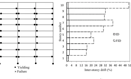
Figure 2. 5: Estimated FID at collapse compared with the IDs measured by Suita et al.
[17] 33
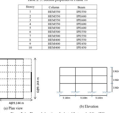
Figure 2. 6: Plan and elevation of selected 3-storey building [20] 36
Figure 2. 7: Plan and elevation of selected 10-storey building [21] 36
Figure 2. 8 :Pushover analysis results for Frame 3 (a) Relationship between base shear and roof drift, (b) ID obtained from pushover analysis as compared with the
proposed collapse ID limits (c) Observed damage at collapse 39
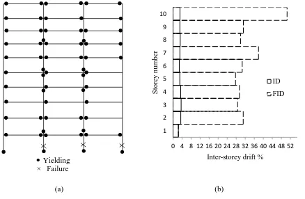
Figure 2. 9: Pushover analysis results for Frame 10 (a) Relationship between base shear and roof drift, (b) ID obtained from pushover analysis as compared with the
proposed collapse ID limits (c) Observed damage at collapse 40
Figure 2. 10: Elastic response spectral acceleration for horizontal seismic component 42 Figure 2. 11: Results of Frame 3 considering horizontal component of Imperial
earthquake at Sa(T1) = 10.10g (a) Distribution of yielding (b) ID compared
with FID limits 44
Figure 2. 12: Results of Frame 3 considering horizontal component of Loma earthquake at Sa(T1) = 32.71g (a) Distribution of yielding (b) ID compared with FID
limits. 44
Figure 2. 13: Results of Frame 3 considering horizontal component of Northridge earthquake at Sa(T1) = 13.92g (a) Distribution of yielding (b) ID compared
with FID limits. 45
Figure 2. 14: Results of Frame-3 considering horizontal component of San Fernando earthquake at Sa(T1) = 17.1g (a) Distribution of yielding (b) ID compared with
FID limits. 45
Figure 2. 15: Results of Frame 3 considering horizontal component of Tabas earthquake at Sa(T1) = 14.75g (a) Distribution of yielding (b) ID compared with FID
limits. 45
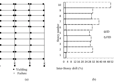
Figure 2. 16: Results of Frame 10 considering horizontal component of Imperial earthquake at Sa(T1) = 0.348g (a) Distribution of yielding (b) ID compared
with FID limits. 46
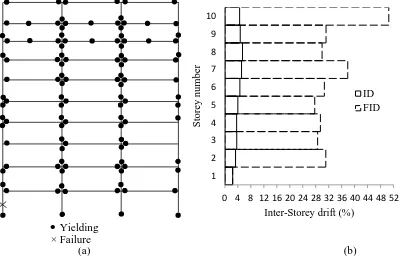
Figure 2. 17: Results of Frame 10 considering horizontal component Northridge earthquake at Sa(T1) = 0.424g (a) Distribution of yielding (b) ID compared
xiv
Figure 2. 18: Results of Frame 10 considering horizontal component of San Fernando Earthquake at Sa(T1) = 0.339g (a) Distribution of yielding (b) ID compared
with FID limits. 47
Figure 2. 19: Results of Frame 10 considering horizontal component of Tabas earthquake at Sa(T1) = 0.351g (a) Distribution of yielding (b) ID compared with FID
limits. 47
Figure 2. 20: Results of Frame 10 considering horizontal component of Loma earthquake at Sa (T1) = 0.573g (a) Distribution of yielding (b) ID compared with FID
limits. 48
Figure 2. 21: Comparison of YDL and ID for horizontal component of Northridge [Sa
(T1) = 0.424g] and Loma Earthquake [Sa (T1) = 0.573g] 49
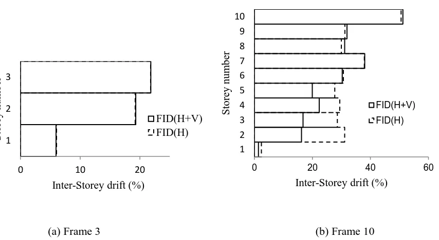
Figure 2. 22: Proposed Limiting FID considering horizontal and both horizontal and
vertical components of ground motion. 50
Figure 2. 23: Results of Frame 3 considering horizontal and vertical component of Loma earthquake at Sa(T1) = 31.87g (a) Yielding distribution (b) ID compared with
FID 52
Figure 2. 24: Results of Frame 3 considering horizontal and vertical component of Northridge earthquake at Sa(T1) = 13.67g (a) Yielding distribution (b) ID
compared with FID 52
Figure 2. 25: Results of Frame 3 considering horizontal and vertical component of San Fernando earthquake at Sa(T1) = 17.25g (a) Yielding distribution (b) ID
compared with FID 52
Figure 2. 26: Results of Frame 3 considering horizontal and vertical component of Imperial earthquake at Sa(T1) = 10.14g (a) Yielding distribution (b) ID compared with
FID 53
Figure 2. 27: Results of Frame 3 considering horizontal and vertical component of Tabas earthquake at Sa(T1) = 15.07g (a) Yielding distribution (b) ID compared with
FID 53
Figure 2. 28: Results of Frame 10 considering horizontal and vertical component of Loma earthquake at Sa(T1) = 0.325g (a) Yielding distribution (b) ID compared with
FID 54
Figure 2. 29: Results of Frame 10 considering horizontal and vertical component of Imperial earthquake at Sa(T1) = 0.271g (a) Distribution of yielding (b) ID
compared with FID limit 54
Figure 2. 30: Results of Frame 10 considering horizontal and vertical component of Northridge earthquake at Sa(T1) = 0.313g (a) Distribution of yielding (b) ID
compared with FID limit. 55
Figure 2. 31: Results of Frame 10 considering horizontal and vertical component of Tabas earthquake at Sa(T1) = 0.27g (a) Distribution of yielding (b) ID
xv
Figure 2. 32: Results of Frame 10 considering horizontal and vertical component of San Fernando earthquake at Sa(T1) = 0.244g (a) Distribution of yielding (b) ID
compared with FID limit. 56
Figure 3. 1: 10-storey building [23] 65
Figure 3. 2: Elastic response spectral acceleration for horizontal seismic component 67
Figure 3. 3: Damage distribution of the steel frame (Frame 1) 68
Figure 3. 4: Location of SMA connections 70
Figure 3. 5: Location of SMA connections 71
Figure 3. 6: Finite element model of martensite SMA connection 72
Figure 3. 7: Experimental and simulated moment rotation behaviour of the superelastic
SMA connection 72
Figure 3. 8: Experimental and simulated moment rotation behaviour of martensite SMA
connection 73
Figure 3. 9: Comparison of MID and MRID of different frames 75
Figure 3. 10: Imperial earthquake [Sa(T1,5%)=0.341g] 76
Figure 3. 11: Damage distribution of the Frame 2 79
Figure 3. 12: Damage distribution of the Frame 3 80
Figure 3. 13: Damage distribution of the Frame 4 81
Figure 3. 14: Damage distribution of the Frame 5 82
Figure 3. 15: Damage distribution of the Frame 6 83
Figure 3. 16: Damage distribution of the Frame 7 84
Figure 4. 1:A typical plan and section of a modular steel building [1] 92
Figure 4. 2: Six-storey modular steel braced frames 94
Figure 4. 3: Comparison of numerical and experimental responses 97
Figure 4. 4: Geometry of MSBF tested by Annan et al. [2] 97
Figure 4. 5: Model of vertical connection of MSBF 98
Figure 4. 6: Comparison of experimental and numerical results 98
Figure 4. 7: Elastic response spectra 100
Figure 4. 8: ID and RID distribution for Frame 1 at collapse 101
Figure 4. 9: Damage distribution of Frame 1 at collapse 104
Figure 4. 10: Different configurations for the SMA braces 105
Figure 4. 11: Braced bay of SMA-MSBF 106
Figure 4. 12: Drift values at intensity causing collapse to Frame 1 108
Figure 4. 13: Storey drifts for Imperial earthquake [Sa(T1, 5%)=3.84g] 108
Figure 4. 14: Storey drifts for Tabas earthquake [Sa(T1, 5%)=5.95g] 109
Figure 4. 15: Storey drifts for Loma earthquake [Sa (T1, 5%)=3.95g] 109
Figure 4. 16: Storey drifts for Northridge earthquake [Sa (T1, 5%)=2.81g] 110
Figure 4. 17: Storey drifts for Superstation hill earthquake [Sa(T1,5%)=3.36g] 110
Figure 4. 18: Damage distribution of Frame 2 112
xvi
Figure 4. 20: Damage distribution of Frame 4 114
Figure 4. 21: Damage distribution of Frame 5 115
Figure 4. 22: Damage distribution of Frame 6 116
Figure 4.23: Load- deformation curve of a first storey steel brace (Frame 1) due to
Tabas earthquake, Sa(T1) =5.95g 117
Figure 4.24 Load- deformation curve of a first storey SMA brace (Frame 2) due to
Tabas earthquake, Sa(T1) =5.95g 117
Figure 5. 1: Vertical connections between upper and lower modules 124
Figure 5. 2: Six-storey modular steel braced frames 127
Figure 5. 3: Locations of SMA connections 128
Figure 5. 4: Finite element model of MSBF 130
Figure 5. 5: Geometry of MSBF tested by Annan et al. [3] 131
Figure 5. 6: Model of vertical connection of MSBF 132
Figure 5. 7: Comparison of experimental and numerical results 132
Figure 5. 8: Bolted end-plate connection 134
Figure 5. 9: Comparison of experimental and simulated moment rotation behaviour of
bolted connection 134
Figure 5. 10: Finite element model of superelastic SMA connection 135
Figure 5. 11: Moment rotation behaviour of the superelastic SMA connection 135
Figure 5. 12: Elastic response spectral acceleration 137
Figure 5. 13: Damage distribution of Frame 1 139
Figure 5. 14: Drifts considering Loma earthquake 141
Figure 5. 15: Drift considering Tabas earthquake 142
Figure 5. 16: Drifts considering Northridge earthquake 142
Figure 5. 17: Drifts considering Superstation Hill earthquake 143
Figure 5. 18: Drifts considering San Fernando earthquake 143
Figure 5. 19: ID and RID distribution considering Loma earthquake at Sa
(T1,5%)=1.2g 145
Figure 5. 20: ID and RID distribution due to Tabas earthquake at Sa(T1,5%)=1.2g 145
Figure 5. 21: ID and RID distribution due to Northridge earthquake at
Sa(T1,5%)=1.2g 146
Figure 5. 22: ID and RID distribution due to Superstation Hill earthquake at
Sa(T1,5%)=1.2g 146
Figure 5. 23: ID and RID distribution due to San Fernando earthquake at
Sa(T1,5%)=1.2g 147
Figure 5. 24: Damage distribution due to Loma earthquake Sa(T1,5%)=1.3g 149
Figure 5. 25: Damage distribution due to Tabas earthquake Sa (T1, 5%) =1.5g 150
Figure 5. 26: Damage distribution due to Northridge earthquake Sa(T1,5%)=1.3g 151
Figure 5. 27: Damage distribution due to Superstation Hill earthquake Sa (T1,5%)
=1.5g 152
xvii
Figure 5. 29: Rotation of vertical connection at first floor due to Tabas earthquake [Sa
xviii
LIST OF NOTATIONS
bf Flange widthdct Moment distribution factor
Es Modulus of elasticity
Fye Expected yield strength of material
h Web height
hc Column height
Ib Beam moment of inertia
Ic Column moment of inertia
Kb Factor for moment at bottom of column
Kc Stiffness of column
Kt Factor for moment at top of column
K1, K2 K3 & K4 Stiffness of beam
L Beam span
m Drift magnification factor
mav Average drift magnification factor
Mcb Moment acting at bottom of column
Mct Moment acting at top of column
P Axial force
PCL Lower bound compression strength of column
tf Flange thickness
tw Web thickness
Vf Shear force for fully restrained column
Vi Shear force for partially restrained column
α Reduction factor for lateral stiffness
Δm Inter-storey drift
θy Yield rotation
ASMA Area of SMA bars
BRB Buckling restrained braces
BRBF Buckling restrained braced frame
xix
FID Failure inter-storey drift
Fy Yield stress of steel
Fy(SMA) Stress at which SMA state changes from the
austenite to stress-induced martensite
ID Inter-storey drift
IDA Incremental dynamic analysis
MID Maximum inter-storey drift
Mpb Plastic moment of beam
MRID Maximum residual inter-storey drift
MSB Modular steel building
MSBF Modular steel braced frame
PGA Peak ground acceleration
PR Partially restrained
PT Post tensioned
RC Reinforced concrete
RID Residual inter-storey drift
Sa Spectral acceleration
SMA Shape memory alloy
SMRF Steel moment resisting frame
V/H Vertical-to-horizontal peak ground acceleration
CHAPTER 1
INTRODUCTION
1.1
INTRODUCTION
The recent earthquakes in Nepal and Japan have shown that seismic damage can be
extensive. Every year, earthquakes take the lives of thousands of people, and destroy
properties that worth billions of dollars. The seismic design philosophy allows structure to
deform and dissipate the seismic energy while, experiencing inelastic deformations. The
resulting seismic residual drifts complicate the repair of damaged structures or render them
as irreparable which have forced researchers to innovate to find alternative design
procedures.
Steel moment resisting frames (SMRFs) and steel braced frames are widely used as lateral
load resisting systems for mid-to high-rise buildings. After 1994 Northridge earthquake,
significant research was conducted to improve their seismic performance. Response
parameters that assess the global seismic performance of steel structures include maximum
roof drift, maximum inter-storey drift, and base shear force.
Nowadays, Modular steel structures are becoming very popular as an effective alternative
to traditional on-site steel construction. In modular construction, units are built and
finished under a controlled manufacturing environment. They are then transported to the
building site, where they are connected horizontally and vertically. The lateral force on
each floor level is transferred through the horizontal connections to the modular braced
is more advantageous over the regular construction because of their reduced construction
duration and highly controlled quality.
Shape memory alloys (SMAs) have widely attracted the attention of researchers because
of their unique material properties. Superelastic SMA has the ability to undergo large
deformations and recover all the plastic deformations upon unloading. Their utilization in
steel structures can significantly reduce seismic residual deformations, which can facilitate
post-seismic retrofitting.
Although the existing literature provides few research data on using SMA in beam-column
connections and bracing elements of steel frames, previous research did not address their
minimum use. Also, the use of SMA in modular steel structures was not examined. This
study examines the potential use of SMAs in steel moment resisting frames (SMRFs) and
modular steel braced frames (MSBFs). The study also explores the possibility of using
SMA material economically at certain locations to minimize the cost and optimize the
seismic performance. The following sections present a brief background and literature
review on the topic, the objectives and scope of this study and the organization of the thesis.
1.2
LITERATURE REVIEW
This section provides an overview of current design philosophy of earthquake resistant
steel structures, modular construction, and published research on the application of SMA
1.2.1 Design philosophy of steel moment resisting frames
Seismic design of steel moment resisting frames (SMRFs) is based on the strong column
and week beam (SC-WB) concept, where ductility is provided by formation of flexural
plastic hinges at the beam faces as shown in Figure 1.1. This concept is followed in many
design standards [1-3]. Schneider et al. [4] showed that meeting the SC-WB requirement
increases the seismic energy dissipation capacity through flexural yielding of the beams at
multiple levels before yielding of columns. Besides ensuring this SC-WB criteria, the
beam-to-column connections of special moment resisting frames should be designed to
sustain a storey drift angle of at least 0.04 radian [3].
As an alternative to welded connections, partially restrained (PR) bolted connections have
been recommended by many researchers [5-7]. These connections are designed to form the
plastic hinges through yielding of their elements. Research has shown that properly detailed
PR connections have good seismic performance and can be considered as a viable
alternative to fully restrained connections [5-7]. The plastic moment capacity of these
connections is typically a fraction of that of the connected framing elements, encouraging
the inelastic behavior to occur within the connection.
Figure 1. 1: Inelastic behaviour of frame with plastic hinges in the beam
Undeformed Frame
Drift angle
1.2.2 Design philosophy of braced frames
The design philosophy of steel braced frames ensures that plastic deformations occur only
in the braces, leaving the beams, columns and connections undamaged. Thus, the structure
is expected to survive strong earthquakes without losing its stability for supporting gravity
loads.
Conventional steel bracing elements show unsymmetrical behaviour under cyclic loading,
Figure 1.2. It is characterized by high ductility in tension and buckling in compression. To
overcome the limitations of brace buckling of conventional braces, buckling restrained
braces (BRB) were proposed by a team of investigators in Japan [8-10]. A BRB has two
basic components: a steel core element that supports the entire brace axial force, and a
restraining exterior element that prevents the core from buckling in compression. BRBs
have stable, predictable hysteretic behaviour and provide significant energy dissipation and
large ductility, Figure 1.2.
In Canada, CSA S16-09 [1] introduced provisions for the design of BRBFs in 2009. The
beam-to column connections of BRBFs are typically non moment resisting connections.
The code restricts the height of BRBFs to 40 meters in moderate and high seismic regions
to eliminate the risk of a soft-storey response. For taller structures BRBs can be used if
inelastic dynamic stability is demonstrated.
1.2.3 Modular construction
A modular building consists of multiple prefabricated units called “Modules”. These units
are manufactured in a controlled manufacturing industry and transported to the
construction site. They are then connected to form the building. Modular construction is
mainly used where repetitive units are required, such as in hospitals, office buildings,
student accommodation, apartments, etc. Their popularity is increasing because of their
quality, fast on-site installation, and lower cost of construction. They are generally used in
low-rise buildings (up to six storey). Lawson and Richards [11] reviewed recent modular
technologies and proposed a design method for high-rise-modular buildings that accounts
for the installation and construction tolerance. Lawson et al. [12] considered case studies
of 12, 17 and 25 storey modular buildings. They recommended the use of steel or concrete
frames to achieve structural stability for high-rise modular buildings. Annan et al. [13-15]
investigated the seismic performance of modular steel braced frames (MSBFs). They
emphasized that the seismic performance of MSBFs is significantly different from regular
steel braced frames. Such difference is attributed to the existence of ceiling beams, the
eccentricity developed at the joints as the braces do not intersect at a single working point,
the semi-rigid connections between the columns of a module and the ones above or below
due to the intrinsic redundancies in the frame system [14]. Fathieh and Mercan [16]
analytically studied the seismic performance of MSBF using two and
three-dimensional(3D) models of a four storey modular steel building. They concluded that the
MSBFs can resist higher base shear than that of the regular traditional steel buildings.
Although, modular steel building systems differ significantly from traditional on-site
buildings in terms of behaviour, detailing requirements and method of construction, there
is no guidelines for their design in CAN/CSA S16-09 [1] or in the National Building Code
of Canada [17].
1.2.4 Drawbacks of current design philosophy
Although the current design philosophy guarantees the life safety level during earthquakes,
it allows severe damage to form in the beams, connections, or braces. Such damage leads
to residual drifts [18-23] that render structural retrofitting as uneconomical.
Researchers are trying to find alternative design procedures to overcome the residual
deformations of structures after a seismic event. Special types of post-tensioned (PT) PR
connections were proposed [21-23] due to their recentering capability as shown in Figure
1.3. The posttensioning contributed to the moment capacity of the connections and
provided an elastic restoring force that returned the frame to its pre-earthquake position.
Six full- scale interior PT connections were tested by Garlock et al. [22] under cyclic
loading. The seismic energy was dissipated by the inelastic deformations of top and bottom
seat angles while the beams and columns remained elastic up to 4% drift. Ricles et al. [21]
conducted dynamic analysis of a six-storey SMRF equipped with PT connections. The
Christopoulos et al. [23] proposed a PT energy dissipating connection for steel frames. This
connection incorporates post-tensioned high strength steel bars to provide self-centering
response and energy dissipating bars to dissipate the seismic energy. The proposed
connection was able to undergo large inelastic deformation without any damage in the
beam or column, and no residual drifts were observed.
Figure 1. 3: Post-tensioned connection [21]
Shape memory alloy (SMA) material has also attracted the attention of researchers because
of its self-centering and energy dissipation capability. Several studies have been conducted
in the past twenty years to explore the use of SMA in new civil structures as well as for
1.2.5 Shape memory alloys
Shape memory alloys based on Nickel and Titanium (NiTi) are found to be the most
suitable alloy for construction applications [24]. NiTi alloy has two stable phases:
austenite, which is stable at high temperatures and low stresses; and mertensite, which is
stable at low temperatures and high stresses. The martensite start temperature (Ms),
martensite finish temperature (Mf), austenite start temperature (As) and austenite finish
temperature (Af), define the temperatures of phase transformations. Figure 1.4 shows the
hysteric behaviour of NiTi SMA during cooling and heating. When the stress is induced to
a twinned martensite SMA at a temperature below Mf, the twinned martensite transforms
to detwinned martensite showing large deformation (6%-8%). By heating the detwinned
martensite to a temperature above Af, the martensite SMA transforms to austenite phase
and regains undeformed shape. This characteristic is called the shape memory effect. If the
SMA is in the austenite phase at a temperature greater than Af, stress-induced large
deformation occurs due to phase transformation from austenite to stressed detwinned
martensite. By removal of the load, the material returns back to austenite, and, thus regain
the residual deformation. without the application of heat. This effect is known as
Figure 1. 4: Three-dimensional stress-strain-temperature diagram of NiTi shape memory alloy [25]
Different types of material models of SMAs are proposed in the literature. Among them,
one-dimensional uniaxial material models were proposed to model superelastic SMA
[26-29]. Different commercial software packages including ANSYS, ABAQUS, OPENSEES
and SEISMOSTRUCT implemented the superelastic SMA material model proposed by
Auricchio et al. [27], Auricchio and Taylor [28], and Auricchio and Sacco [29],
respectively. The parameters used to define the material are: 1) austenite to martensite
stress, 4) martensite to austenite finishing stress, 5) length of superelastic plateau strain or
maximum residual strain, and 6) modulus of elasticity.
1.2.5.1 Application of SMA in reinforced concrete structures
Several studies have been conducted to improve the seismic performance of reinforced
concrete structures by utilizing SMA in columns, beams, beam-column connections, and
shear walls. Wang [30] conducted a shake table test to investigate the seismic performance
of reinforced concrete (RC) columns. SMA longitudinal reinforcement was used in the
plastic hinge area and steel reinforcement was used in other areas. Using SMA reduced the
residual displacements of the tested columns. Billah and Alam [31] incorporated SMA and
fiber reinforced polymer bars in RC columns to reduce seismic residual deformations as
well as enhance corrosion resistance. Superleastic SMA was used in plastic hinge region
to reduce the permanent damage and FRP was used in remaining regions to enhance its
corrosion resistance The corrosion-resistant hybrid- column had significantly reduced
seismic residual deformations. RC beams utilizing SMA bars were tested under cyclic
loading by Ayoub et al. [32]. The results showed that SMA bars reduce residual
deformations of the beams by more than 75% and minimize the permanent width of cracks.
Abdulridha et al. [33] investigated the structural performance of RC beams utilizing
superelastic SMA bars. The tested SMA beams showed higher ductility and strength
capacity, and were able to recover the inelastic deformations. The structural performance
of a RC shear wall utilizing SMA bars was assessed analytically by Ghassemieh et al. [34].
They conducted parametric studies using different percentage of SMA bars along with
regular steel bars. The study revealed that replacing more than 50% of the steel rebars with
al. [35] tested RC beam- column joints with superelastic SMA bars in the plastic hinge area
under reverse cyclic loading. SMA reinforced beam-column joints were able to recover
most of their inelastic deformations. The location of the plastic hinge was also shifted from
the face of the column by approximately half of the beam-depth.
Alam et al. [36] analytically evaluated the seismic performance of an eight-storey SMA
RC frame using SMA bars at the plastic hinge areas of all beams. The SMA RC frame had
reduced residual inter-storey drifts (RID) compared with a Steel-RC frame. Because of the
relatively high cost of SMA bars, Youssef and Elfeki [37] analytically investigated the
possibility of reducing the amount of SMA bars while keeping the benefit of reducing the
RID. A six-storey steel-RC building was designed and exposed to incremental dynamic
analyses. The frame was then redesigned using superelastic SMA bars at critical locations.
The study concluded that using SMA bars at the critical beams as well as the beams
intersecting with the critical columns lead to the best seismic performance in terms of
maximum residual inter-storey drift (MRID) and damage scheme.
SMAs are also used for retrofitting deficient RC structures. Dolce et al. [38] retrofitted an
existing 2-storey RC frame using special braces incorporating superplastic NiTi SMA
wires. Experimental tests were carried out to assess the cyclic behaviour of the retrofitted
structure. The study revealed that using SMA braces provided the strong recentering
capability and increased the safety against collapse. Cardone et al. [39] evaluated the
effectiveness of SMA based bracing devices for seismic retrofitting of RC frames designed
for gravity loads. A shaking table test was carried out on a 3D ¼- scale RC frame model.
The experimental results confirmed the great potential of using SMA based braces in RC
Several researchers have also investigated the seismic performance of bridges utilizing
superelastic SMAs as dampers, base isolators, reinforcements, expansion joints, etc.
[40-43]. Their studies highlighted the effectiveness of utilizing SMA to minimize the residual
deformations of bridges.
1.2.5.2 Application of SMA in steel structures
Ocel et al. [44] first integrated smart shape memory alloy (SMA) into traditional steel
connections. They tested innovative external beam-column connections using mertensite
SMA rods. The beam moment was transferred to the column by four large diameter NiTi
SMA tendons connecting the beam flange to the column flange. Integrating SMAs had
significantly enhanced the ductility and damping capacity of PR connections. In addition,
the unique shape memory behavior provided the possibility of removing the residual
deformations within the connection by heating the SMAs above their transformation
temperature.
Ma et al. [45] investigated an extended SMA end-plate connection by using 3D finite
element model. The results showed cyclic elongations of the SMA bolts in the connection,
which were recoverable upon unloading. Moreover, the ductility of SMA connections was
significantly influenced by the length of the SMA bolts. The inelastic inter-storey drift
angle reached 0.035 rad, which indicated sufficient ductility. A quasi-static test of an
extended SMA end-plate connection was also conducted by Ma and Yam [46]. The
connection showed a high deformation capacity with maximum inter-storey drift angle
A PR connection using copper-based (CuAlBe) shape memory alloy (SMA) bars was
tested by Sep'ulveda et al. [47]. The proposed connection showed self-centering behaviour,
moderate energy dissipation capability, and no strength degradation under 3% drift ratio
cycles. Speicher et al. [48] tested half-scale interior beam-column connection incorporating
superelastic NiTi SMA to assess the feasibility of such a connection in a moment-resisting
frame. This connection was compared to three other connections utilizing tendons made of
steel, martensitic NiTi and superelastic NiTi paralleled with aluminum. The superelastic
NiTi SMA connection showed significant recentering capability and recovered a large
portion of the post-elastic drifts compared to other connections. Wang et al. [49] proposed
an innovative connection that utilize superelastic SMA tendons along with steel tendons to
connect an H shaped beam with a CHS column. The tested connection showed excellent
recentering capability and moderate energy dissipation capacity up to 6% inter-storey drift
angle. Fang et al. [50] conducted eight tests to investigate the cyclic performance of
extended SMA end-plate connections. The connections showed excellent recentering
capability, and moderate energy dissipation capacity. The same research group established
a detailed finite element model of the connection and conducted parametric studies
considering the effects of bolt layout, bolt length/diameter, beam to connection strength
ratio, end plate thickness, column web panel deformation, and shear resistance [51]. Their
recommendations to achieve reliable recentering connections include: 1) the maximum
moment resistance of the connection should be less than the connecting members, 2) thick
extended end plate is required to reduce the residual deformation of the connection and to
result into uniform stress state in the SMA bolts, and 3) the column web panel should have
The global seismic performance of steel moment resisting frames with beam to column
connections using SMA bars was studied by DesRoches et al. [25]. Two steel frames were
selected for this purpose: low rise (three story) PR frame and medium rise (nine story) PR
frame. The connections were considered as mertensite SMA connections or austenite SMA
connections. Nonlinear time history analyses were performed to determine the effect of
SMA connections on peak and residual inter-storey drift demand. SMA connections were
found to be most effective in controlling the structural response under high levels of
seismic intensity. The study showed that superelastic austenite SMA connections were
more suitable for controlling residual deformations while martensitic SMA connections
were most effective in controlling peak deformations. Further probabilistic seismic demand
assessment (PSDA) was also performed by Ellingwood et al. [52] to assess statically the
efficiency of using SMA connections in steel moment resisting frames.
Researchers also investigated the seismic performance of steel braced frames using SMA
in bracing members [53-56]. Auricchio et al. [53] analytically studied the seismic
performance of three- and six-storey steel frame buildings equipped with traditional steel
and superelastic SMA bracings. Incorporating SMA braces reduced the inter-storey drifts
as well as residual inter-storey drifts, and, thus improved the seismic performance
compared with those of steel braced frames. In 2007, McCormic et al. [54] assessed the
performance of concentrically braced steel frames incorporating SMA braces. The results
suggested that SMA braces are effective in limiting residual inter-storey drifts during an
earthquake, due to the recentering capability of superelastic SMA. The seismic
performance of steel braced frames equipped with superelastic SMA braces, considering
bracings, was investigated by Asgarian and Moradi [55]. The results highlighted the
efficiency of SMA braces in reducing the residual roof displacements and peak inter-story
drifts as compared to buckling restrained braced frames. Kari et al. [56] conducted a
numerical study to investigate the benefits of using combination of buckling restrained
braces and shape memory braces (dual bracing). Results revealed that, with the proper
configuration, both minimum residual and inter-storey drifts can be attained.
Miller [57] experimentally investigated the seismic performance of self-centering
buckling-restrained braces (SC-BRBs) that utilized the benefits of energy dissipation
capacity of buckling restrained brace (BRB) components and recentering ability of
superelastic NiTi SMA rods. The rods were attached to the BRB portion of the brace using
a set of concentric tubes and free-floating anchorage plates in such a way that caused the
SMA rods to elongate when the brace was in tension or compression. The braces exhibited
stable and flag-shaped hysteretic response under cyclic loading. The study concluded that
proper proportioning of the SMA pretension force and the BRB core yield force, influenced
the full re-centering capacity of the bracing.
1.3
OBJECTIVES AND SCOPES
The primary aim of this thesis is to enhance the seismic performance of both regular and
modular steel structures using certain amount of superelastic SMAs material. This was
1) Conduct a thorough literature review that summarizes the current seismic design
philosophy of steel moment resisting frames, concentrically braced steel frames,
modular steel braced frames, the characteristics of SMA material and its
applications in civil engineering structures.
2) Develop and validate a simplified method based on pushover analysis to predict the
location of seismic damage in steel moment resisting frames (SMRFs) considering
both horizontal and vertical seismic components. Implement this method to identify
the critical floors of a steel moment resisting frames.
3) Develop finite element model of SMA beam-column connection that can represent
the hysteretic moment-rotation behavior of the connection accurately. Implement
that model to study analytically the seismic performance of SMRFs.
4) Implement the simplified method proposed in step 2 as well as nonlinear dynamic
analysis to determine the best locations of SMA connections to improve the seismic
performance of SMRF at minimum cost.
5) Develop analytical model that can accurately predicts the seismic behavior of
modular steel braced frames (MSBFs) equipped with buckling restrained SMA
braces and implement this model to identify the locations of SMA braces to
improve the seismic performance.
6) Assess seismic performance of modular steel braced frames connected vertically
1.4
ORGANIZATION AND OUTLINE
The dissertation comprises of six chapters. In the present chapter, a review of the current
design philosophy of steel moment resisting frames, steel braced frames and modular steel
buildings has been discussed. Properties of SMAs, their application in civil structures along
with the scope and objectives of the research are then outlined. The following four chapters
address the stated objectives. The thesis concludes by chapter six that briefly summarize
the obtained conclusions, the major contributions and recommendations for future studies.
Contents of chapter 2 to 5 are summarized below.
1.4.1 Prediction of local seismic damage in steel moment resisting frames
Steel moment resisting frames (SMRFs) are widely utilized as a lateral load resisting
system. Their seismic performance is usually assessed by examining the maximum value
of inter-storey drift (MID) of all floors. The accuracy of such assessment is debatable given
the wide spread of values of MID at collapse that exist in the literature. In chapter 2, a
simplified method to define the failure inter-storey drift for each floor of a SMRF is
proposed. The method is validated with the experimental and analytical studies by other
researchers. Three- and ten storey SMRFs are considered to further validate the proposed
method. The effects of the vertical and/or horizontal seismic components of five different
1.4.2 Seismic performance of steel moment resisting frames utilizing superelastic
shape memory alloys
Steel structures dissipate the seismic energy through steel yielding, which results in
residual deformations. Although conventional earthquake-resisting structural systems
provide adequate seismic safety, they experience significant structural damage when
exposed to strong ground shaking. Therefore, systems that can minimize the seismic
residual deformations are needed. Superelastic shape memory alloys (SMAs) have the
ability to undergo large deformations and recover all plastic deformations upon unloading.
Their utilization in steel structures can significantly reduce seismic residual deformations,
which will facilitate post-seismic retrofitting. In chapter 3, the seismic performance of
SMRFs equipped with superelastic SMA connection is investigated. The proposed
simplified method developed in chapter 2 as well as incremental dynamic analysis is
applied to identify the required locations of SMA connections in a typical SMRF to
enhance its seismic performance in terms of maximum inter-storey drift, residual
deformations, and damage scheme.
1.4.3 Seismic performance of modular steel frames equipped with shape memory
alloy braces
The demand for modular steel buildings (MSBs) has increased because of the improved
quality, fast on-site installation, and lower cost of construction. Steel braced frames are
usually utilized to form the lateral load resisting system of MSBs. During earthquakes, the
seismic energy is dissipated through yielding of the components of the braced frames,
performance of typical modular steel braced frames (MSBFs) is explored in chapter 4
utilizing incremental dynamic analysis.
1.4.4 Seismic performance of modular steel braced frames utilizing superelastic
shape memory alloy bolts in the vertical module connections
In modular construction, the vertical connections can be achieved by welding or bolting
the columns of stacked modules. The seismic performance of modular steel braced frames
(MSBFs) connected vertically using superelastic shape memory alloy (SMA) bolts is
investigated in chapter 5. The required locations of SMA connections in a typical MSBF
are identified to optimize its seismic performance in terms of maximum inter-storey drift,
1.5
REFERENCES
[1] CAN/CSA-S16-09, Design of Steel Structures, Canadian Standard Association,
2009.
[2] FEMA 350, Recommended Seismic Design Criteria for New Steel
Moment-Frame Buildings Federal Emergency Management Agency 2000.
[3] AISC 341-10, Seismic Provisions for Structural Steel Buildings, American
Institute of Steel Construction, 2002.
[4] S.P. Schneider, C.W. Roeder, J.E. Carpenter, Seismic performance of
weak-column strong-beam steel moment resisting frame, Final report, Department of
Civil Engineering, University of Washington, Seattle, WA 1991.
[5] J.C. Awkar, L. M. Lui, Seismic analysis and response of multistory semirigid
frames, Eng. Struct. 21 (1999), 425–441
[6] J.A. Swanson, R.T. Leon, Bolted steel connections: tests on T-stub components.
J. Struct. Eng. 126(1) (2000) 50–56.
[7] E.A. Sumner, T.M. Murray, Behavior of extended end-plate moment connections
subject to cyclic loading, J. Struct. Eng. 128 (4) (2002) 501-508.
[8] A.Wada, E. Saeki, T. Takeuch, A. Watanabe, Development of unbonded brace,
Column technical publication no 115, Nippon steel, Japan 1989.
[9] A. Watanabe, Y. Hitomoi, E. Saeki, A. Wada, M. Fujimoto, Properties of braced
encased in buckling-restraining concrete and steel tube. In Proceedings of 9th
World Conference on Earthquake Engineering, Tokyo-Kyoto, Japan, Vol. IV
(1988) 719-724.
[10] A. Watanabe, H. Nakamura, Study on the behavior of buildings using steel with
low yield point, In Proceedings of 10th World Conference on Earthquake
Engineering, Balkema, Rotterdam , The Netherlands , 1992, 4465-4468.
[11] R. M. Lawson, J. Richards, Modular design for high-rise buildings, Proceedings
of the Institution of Civil Engineers, Structures and Buildings, 163 (SB3)
(2010)151–164.
[12] R.M. Lawson, R. R.G. Ogden, R. Bergin, Application of modular construction in
[13] C.D. Annan, M.A. Youssef, M.H. El Naggar, Experimental Evaluation of the
Seismic Performance of Modular Steel-Braced Frames. Eng. Struct., 31(7) (2009)
1435-1446.
[14] C.D. Annan, M.A. Youssef, M.H. El Naggar, Seismic overstrength in braced
frames of modular steel buildings, J. Earthq. Eng. 13(1) (2009)1-21.
[15] C.D Annan, M.A. Youssef, M.H. El Naggar, Seismic vulnerability assessment of
modular steel building. J. Earthq. Eng. 13(8) (2009) 1065-1088.
[16] A. Fathieh, O. Mercan, Seismic evaluation of modular steel building, Eng. Struct.,
122 (2016) 83-92.
[17] NBCC 2005, National building code of Canada.
[18] C. Ariyaratana, L.A. Fahnestock, Evaluation of buckling-restrained brace frame
seismic performance considering reserve strength, Eng. Struct. 33 (2011) 77-89.
[19] L.A. Fahnestock, R. Sause, J.M Ricles, Seismic response and performance of
buckling restrained braced frames, J. Struct. Eng. 133 (9) (2007)1195-1204.
[20] R. Shabelli, S. Mahin, C. Chang, Seismic demand on steel braced frame buildings
with buckling-restrained braces, Eng. Struct. 25(5) (2003) 655-666.
[21] J.M. Ricles, R. Sause, M.M. Garlock, C. Zhao, Posttensioned seismic-resistant
connections for steel frames, J. Struct. Eng. 127(2) (2001) 113-121.
[22] M.M. Garlock, J. M. Ricles, R. Sause, Experimental studies of full-scale
posttensioned steel connection, J. Struct. Eng. 131 (2005) 438–448.
[23] C. Christopoulos, A. Filiatrault, C. Uang, B. Folz, Posttensioned energy
dissipating connections for moment-resisting steel frames, J. Struct. Eng. 128
(2002) 1111–1120.
[24] J. McCormick, J. Tyber, R. DesRoches, k. Gall, H. Maier, Structural engineering
with NiTi Part II: Mechanical behavior and scaling, J. Eng. Mech. 133(9) (2007)
1019-1029.
[25] R. DesRoches, B. Taftali, B.R. Ellingwood, Seismic performance assessment of
steel frames with shape memory alloy connections, Part I- Analysis and seismic
demands, J. Earthq. Eng. 14 (2010) 471-486.
[26] F. Auricchio, J. Lubliner, Uniaxial model for shape-memory alloys. Int. J. Solids.
[27] F. Auricchio, R.L. Taylor, J. Lubliner, Shape-memory alloys: macro modelling
and numerical simulations of the superelastic behaviour. Comput. Methods. Appl.
Mech. Eng. 146 (1997) 281-312.
[28] F. Auricchio, R.L. Taylor, Shape memory alloy superelastic behavior: 3D finite
element simulations. Proceedings of SPIE - The International Society for Optical
Engineering, 2779 (1996) 487-492.
[29] F. Auricchio, E. Sacco, Superelastic shape-memory-alloy beam model. J. Intell.
Mater. Syst. Struct, 8 (1997) 489-501.
[30] H. Wang, A study of RC columns with shape memory alloy and engineered
cementitious composites. M.Sc. Thesis, University of Nevada, Reno, USA, 2004.
[31] A.H.M.M. Billah, M.S.Alam, Seismic performance of concrete columns
reinforced with hybrid shape memory alloy (SMA) and fiber reinforced polymer
(FRP) bars, Construction and Building Materials 28 (2012) 730-742
[32] C. Ayoub, M. Saiidi, A. Itani, A, A Study of Shape-Memory-Alloy-Reinforced
beams and Cubes, Center for Civil Engineering Earthquake Research, Report No.
CCEER-03-7, Department of Civil Engineering, University of Nevada, Reno,
Nevada, 2004.
[33] A. Abdulridha, D. Palermo, S. Foo, F.J. Vecchio, Behavior and modeling of
superelastic shape memory alloy reinforced concrete beams, Eng. Struct. 49
(2013) 893–904.
[34] M. Ghassemieh, M. Mostafazadeh, M.S. Sadeh, Seismic control of concrete shear
wall using shape memory alloys, J. Intell. Mater. Syst. S, 23(5) (2012) 535-543.
[35] M.A. Youssef, M.S. Alam, M. Nehdi, Experimental investigation on the seismic
behaviour of beam-column joints reinforced with superelastic shape memory
alloys, J. Earthq. Eng.12(7) (2008) 1205-1222.
[36] M.S. Alam, M. Nehdi, M.A. Youssef, Seismic Performance of concrete frame
structures reinforced with superelastic shape memory alloys, Smart. Struct. Syst.
5(5) (2009) 565-585.
[37] M.A. Youssef, M.A. Elfeki, Seismic performance of concrete frames reinforced
[38] M. Dolce, D. Cardone, R. Marnetto, M. Mucciarelli, D. Nigro, F.C. Ponzo, G.
Santarsiero, Experimental static and dynamic response of a real R/C frame
upgraded with SMA recentering and dissipating braces, 13th world conference on
earthquake engineering, Vancouver, Canada, 2004, paper no. 2878.
[39] D. Cardone, M. Dolce, F.C. Ponzo, E. Coelho, Experimental behaviour of R/C
frames retrofitted with dissipating and re-centering braces. J. Earthq. Eng. 8
(2004) 361-396.
[40] R. DesRoches, M. Delemont, Design and analysis of innovative dampers for
seismically isolated bridges in the United States, Proceedings of the 7th
international seminar on seismic isolation, energy dissipation, and active control,
Assissi, Italy, November, 2001 (2001)
[41] O.E. Ozbulut, S. Hurlebaus Evaluation of the performance of a sliding-type base
isolation system with a NiTi shape memory alloy device considering temperature
effects, Eng. Struct. 32 (1) (2010), 238–249.
[42] B. Andrawes, R. DesRoches Comparison between shape memory alloy seismic
restrainers and other bridge retrofit devices, J. Bridge. Eng, 12 (6) (2007), 700–
709.
[43] E. McCarthy, T. Wright, J. Padgett, R. DesRoches, P. Bradford Mitigating seismic
bridge damage through shape memory alloy enhanced modular bridge expansion
joints, Struct. Congrss. (2012) 708–717.
[44] J. Ocel, R. DesRoches, R.T. Leon, W.G. Hess, R. Krumme, J.R. Hayes, S.
Sweeney, Steel beam-column connections using shape memory alloys, J. Struct.
Eng. 130 (2004) 732–740.
[45] H. Ma, T. Wilkinson, C. Chongdu, Feasibility study on a self-centering
beam-to-column connection by using the superelastic behavior of SMAs, Smart. Mater.
Struct. 16 (2007) 1555–1563.
[46] H. Ma, M. C. H. Yam, Experimental study on a beam-to-column connection using
Shape Memory Alloy, Adv. Mater. Res. 374-377 (2012) 2176-2179.
[47] J. Sepúlveda, R. Boroschek, R. Herrera, O. Moroni, M. Sarrazin, Steel
beam-column connection using copper-based shape memory alloy dampers, J. Constr.
[48] M.S. Speicher, R. DesRoches, R.T Leon, Experimental results of a NiTi shape
memory alloy (SMA)-based recentering beam-column connection. Eng. Struct. 33
(2011) 2448-2457.
[49] W. Wang, T.M. Chan, H. Shao, Y. Chen, Cyclic behavior of connections equipped
with NiTi shape memory alloy and steel tendons between H-shaped beam to CHS
column, Eng. Struct. 88 (2015) 37–50
[50] C. Fang, M.C.H. Yam, A.C.C. Lam, L. Xie, Cyclic performance of extended
end-plate connections equipped with shape memory alloy bolts, J. Constr. Steel. Res.
94 (2014) 122–136.
[51] M.C.H. Yam, C. Fang, A.C.C. Lam, Y. Zhang, Numerical study and practical
design of beam-to-column connections with shape memory alloys, J. Constr.
Steel. Res. 104 (2015) 177–192.
[52] B.R. Ellingwood, B. Taftali, R. Desroches, Seismic performance assessment of
steel frames with shape memory alloy connections, Part II- Probabilistic demand
assessment, J. Earthq. Eng. 14 (2010) 631-645.
[53] F. Auricchio, D. Fugazza, R. Desroches, Earthquake performance of steel frames
with Nitinol braces, J. Earthq. Eng. 10 (1) (2006) 45–66.
[54] J. McCormick, R. DesRoches, D. Fugazza, F. Auricchio, Seismic assesment of
concentrically braced steel frames with shape memory alloy braces, J. Struct. Eng.
133 (2007) 862-870.
[55] B. Asgarian, S. Moradi. Seismic response of steel braced frames with shape
memory alloy braces, J. Const. Steel. Res. 67(1) (2011) 65-74.
[56] A. Kari, M. Ghassemieh, S.A. Abolmaali, A new dual bracing system for
improving the seismic behavior of steel structures, Smart. Mater. Struct. 20 (12)
(2011) 125020.
[57] D.J Miller, Development and experimental validation of self-centering
buckling-restrained braces with shape memory alloy, M.Sc thesis, University of Illinois at
CHAPTER 2
PREDICTION OF LOCAL SEISMIC DAMAGE IN STEEL
MOMENT RESISTING FRAMES
2.1
INTRODUCTION
Steel moment resisting frames (SMRFs) are widely used as the lateral load resistance
system for mid- to high-rise buildings. After 1994 Northridge earthquake, significant
research was conducted to improve their global seismic performance. While damage of
individual elements (beams, columns, and connections) can be based on their rotations,
damage to the full frame is usually related to the maximum inter-storey drift (MID).
Reported MID values at collapse have large variations in the literature. While FEMA 356
[1] limited the MID for steel structures to 5%, FEMA 350 [2] defined collapse of SMRFs
in midrise buildings (4-12 storeys) to occur at 10% inter-storey drift. The New Zealand
standard [3] limited the MID to 2.5%. UBC 1997 [4] specified MID values of 2.5% and
2.0% for structures with short and long period of vibrations, respectively. The actual MID
depends on many factors including design assumptions, characteristics of the ground
motion, and effect of higher modes of vibrations.
The damage due to the vertical component of a seismic excitation was observed to be very
significant by many researchers [5-7]. The interior columns and interior beams of
moment-resisting frames are significantly affected [5, 6]. The increase in the column axial forces
caused by the vertical excitation of near-field and far-field earthquakes can reach 65% and
rotational ductility demand, and, thus cause significant structural damage [8]. Several
building codes account for the vertical seismic component by assuming that the vertical
design response spectrum is 2/3 of the horizontal design spectrum [1, 4]. Eurocode 8 [9]
and the National Earthquake Hazards Reduction Program [10] define the vertical spectrum
independently from the horizontal spectrum.
The relationship between seismic damage and inter-storey drift (ID) was examined in this
study to allow identification of the severely damaged storeys without the need for
conducting nonlinear incremental dynamic analysis (IDA). The study proposes a simplified
method that can identify the severely damaged floors of SMRFs when exposed to an
earthquake while accounting for the vertical seismic component.
2.2
PROPOSED METHOD
Youssef and Elfeki [11] proposed a simplified method to predict the ID at collapse for
reinforced concrete frames. The method does not account for the P-Δ effect, which might
be appropriate for concrete structures. In this study, the method is further extended to
account for P-Δ effect.
2.2.1 Lateral drift (∆𝒎) based on P-Δ effect
The increase of fixed-end moments and shear forces of columns due to the P-Δ effect are
shown in Figure 2.1 and can be calculated using equations (2.1) and (2.2).
𝑀𝑓 =6𝐸𝑠𝐼𝑐 ℎ𝑐2 ∆𝑚+
𝑃∆𝑚
2 (2.1)
𝑉𝑓 =12𝐸𝑠𝐼𝑐 ℎ𝑐3 ∆𝑚+
𝑃∆𝑚 ℎ𝑐
Figure 2.2 shows an isolated column and the connecting beams. The figure assumes that:
(1) joint rotations are equal for any two successive stories, (2) the stiffness of each beam is
equally utilized by the columns above and below a specific floor (beams are split into
hypothetical halves, each half possesses 50% of the stiffness of the original beam), and (3)
Contra-flexure points are assumed to be at the mid-span of each beam and mid-height of
each column [11-13]. The stiffness is presented in the figure by the ratio K where K = I/L.
Figure 2. 1: Fixed-end moments induced by lateral displacement Δm
If a relative lateral displacement Δm is applied between the column ends, the column
fixed-end moment can be obtained using equation (2.1). As the flexural stiffness of the top beams
and the column are 3EsK1, 3EsK2 and 6EsKc, the moment distribution factor dct can be
calculated using equation (2.3). Applying the principal of moment distribution, the final
moment at the column top (Mct) can be obtained using equations (2.4).
𝑑𝑐𝑡 = 6𝐾𝑐
3𝐾1+ 3𝐾2 + 6𝐾𝑐 = 2
𝐾𝑡+ 2 (2.3)
Where 𝐾𝑡 =𝐾1+𝐾2
𝐾𝑐 .
𝑀𝑐𝑡 = ( 6𝐸𝑠𝐼𝑐
ℎ𝑐2 +𝑃
2) ∆𝑚 𝐾𝑡 𝐾𝑡+ 2
(2.4) ∆𝑚
2 ∆𝑚
2
6𝐸𝑠𝐼𝑐
ℎ𝑐2
∆𝑚
6𝐸𝑠𝐼𝑐
ℎ𝑐2
∆𝑚 Δm hc 𝑃∆𝑚 2 P P 𝑃∆𝑚 2
![Figure 1. 3: Post-tensioned connection [21]](https://thumb-us.123doks.com/thumbv2/123dok_us/7737346.1267214/26.612.236.412.220.458/figure-post-tensioned-connection.webp)
![Figure 1. 4: Three-dimensional stress-strain-temperature diagram of NiTi shape memory alloy [25]](https://thumb-us.123doks.com/thumbv2/123dok_us/7737346.1267214/28.612.119.555.77.390/figure-dimensional-stress-strain-temperature-diagram-niti-memory.webp)
![Table 2. 1: Modeling parameters for nonlinear procedures according to FEMA356 [1]](https://thumb-us.123doks.com/thumbv2/123dok_us/7737346.1267214/51.612.170.478.400.694/table-modeling-parameters-nonlinear-procedures-according-fema.webp)
![Figure 2. 21: Comparison of YDL and ID for horizontal component of Northridge [Sa (T1) = 0.424g] and Loma Earthquake [Sa (T1) = 0.573g]](https://thumb-us.123doks.com/thumbv2/123dok_us/7737346.1267214/68.612.114.537.326.574/figure-comparison-ydl-horizontal-component-northridge-loma-earthquake.webp)