Domotics using labview
G.Shanmugaraj
1, B.Banu
2, S.Suhitha
3S.Merlin
4 1,2,3,4Velammal Institute of Technology
2,3Affiliation of Second Author and Third Author if common Affiliation for both.
Abstract:
In today’s era, technology has advanced to this extent that it can be very useful in domestic purposes. Our house is the center of our domestic life and we can control our daily activities by using technical system. Automating our house activities eases and simplifies the way of living. A house with a smart control system is called Smart Home. The control system is built by using information technology to control the electric appliance and security system. Smart home is a result of continuous change in technology and will keep changing with the advancement in technology. In this paper, we have addressed one of the features of Smart Home which is a sample house environment monitor and control system. This feature has been implemented by using LabVIEW software. The developed system can monitor the temperature, PIR motion sensor, magnetic door sensor and LDR the family security. The system also has internet connection by which it can act as remote system and can be controlled from anywhere in the world. This paper explains the hardware implementation of a multi-platform control system for house automation. The approach is a combination of hardware and software technologies. This system can be easily used for smart home application which is supported by the test results. .
Keywords: domotics, LabVIEW, smart home, Automation, Security.
1.
Introduction
1.1. Smart Home
echnology has advanced so much that a lot of data and instruction can be stored in a small chip. Mobile and handheld devices have brought a revolution in technology. The technology has also invaded our home space and made our daily activities very easy. Smart home is today’s need where the nuclear family is prevalent and both members are earning hand. Smart home system is very useful for family safety precaution as we cannot have manual security 24 hours a day.
Smart system will be very helpful in maintaining a sustainable environment when we can control our electrical dependencies.
Electrical energy is the main energy source in a house and we need to be very careful in its usage. Smart system provides that control to us through which we can monitor our electricity usage.
In this project a system has been developed to control the internal and external lighting, fire alarm and temperature systems of the house. The system has been developed by using LABVIEW software. LABVIEW software is based on graphical programming and also supports textual programming. The software has a varied collection of different functions which can be used for numerical analysis and Visualization of data. This is a popular software development system for industrial, experimental, educational, measurement and automation application. The Smart House’s main system is controlled by LABVIEW. The main system consists of two parts. The first system is a smart house project is lighting system that includes the internal lighting of the house. The second part of the system is used to measure the temperature of the room.
1.2. Lab VIEW
Lab VIEW stands for Laboratory Virtual Instrumentation Engineering Workbench. It started in 1983 by a company National Instrument which famously stands for NI. Like C, JAVA, the Lab VIEW software is known as „G‟ language. Lab view is mainly designed for complex problems.
Lab VIEW is a graphical programming language used to create programs called VI, which are in a pictorial form called a block diagram, which eliminates a lot of the syntactical details of other programming languages like C and MATLAB that use a text based programming approach. Lab VIEW is available for all the major platforms and is easily portable across platforms. It is simple and flexible, since it is a graphical approach no need of writing programs of 100 lines like other program languages. Each VI has two windows-Front Panel and Block Diagram windows. Front Panel is the user interface
which has controls and indicators. The cost of the lab VIEW is the major drawback for not into the application. Thus presently Lab VIEW application is restricted to only high scale applications in industrial levels and yet to shift on the home level. The advantage of Lab VIEW in home automation not only makes it easier to design but also increases the accuracy and speed of the system. The rest of the paper is organized as follows: Section II focuses on the description of lab VIEW and Section III gives the design of the system.
2.
DESCRIPTION OF LABVIEW
We have designed the Smart Home system using LABVIEW software. LABVIEW is a graphical programming language. The application is developed by using different icons. There is no need to write lines of code for developing applications in LABVIEW. A user interface can be built by using a set of tools and objects defined in LABVIEW. There is also a provision to purchase several add on software toolsets. These add on softwares can be used for developing a custom and specialized application. LABVIEW has seamless integration for all the toolsets.
SMART HOUSE is one of the applications of LABVIEW. In our project we have used serial communication, the microcontroller and PC interface through data cable (RS232). The RS232 is one type of serial communication. This is two wire communications. It can be used to send data on a long distance. This type of communication finds its wide usage in process industries, residences, offices, power plant, industrial automation, etc. For example in an industry different parameters like current, voltage, speed, power factor, etc. can be monitored and displayed on a PC with the help of serial communication.
3.
BLOCK DIAGRAM
The general description of the below diagram is as follows, We see the working and the actual logic of the project in that consists mainly three sensors are as LDR circuit, PIR (passive infrared sensor), Door sensor and also consist data acquisition for communication purpose with LAB-VIEW software.
The block diagram for the smart house control is shown in the fig (a).
First the door sensor is sense the door is closed and if open then sends command motion sensor to check where motion is happening in the room or not .If the motion is happening in the room it gives signals then it send signal to an LDR circuit to check whether there is light or dark in the room if there is dark, then only that send signal to LAB-VIEW software to ON the lamp in the room and if there is dark in the room then all commands are fail and light are remains an OFF condition . This all is done by the software control of LABVIEW.
3.1 HARDWARE REQUIREMENTS -PIC16F877A
-Temperature Sensor -GAS Sensor -Relay -Power Supply -Bulb
-Motor
3.2 SOFTWARE REQUIREMENTS -Mplab ide
-Labview
-Pickit2 Programmer
Fig : (a) block diagram for smart house control
4.
DESIGN
4.1 LABVIEW CONTROL
According to the program defined in the Lab View takes various inputs from the connected sensors and processes it then, it provides the corresponding logical output to the whole house power system. In addition to this it also has a power protection system , which helps in trapping the main power source when any fault occurs inside home the protection system..
The Lab VIEW will control the water level indicator, internal lighting, external lighting, motion control,fire alarm, temperature, burglar alarm systems in the house.
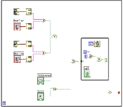
4.1.1 Internal Lighting System
The internal lighting system consists of a motion sensor and lamps which there are connected to Lab VIEW software program. This system will make an automatic lighting in the home when there is any movement inside it. The motion sensor detects whether there is any human presence in the building or not. If not it will send a signal to lab VIEW and it switches off the device in the building. If there is human presence the device will be switched on automatically. If we don‟t want the lamp to glow, it can be manually switched off. The timer circuit is used for some specific area where the lamp glows for a fixed period of time.
Fig (b) block diagram for internal lighting system
4.1.2
External Lighting System:
The external lighting system consists of suncell, dimmers and lamps which are in contact with the lab VIEW software program. The external lighting system depends on the reading of sun cell. The output of the sensor will be in analog form. Depending on the time the Lab VIEW software program controls the status of external light lamps. Dimmer can use to make a small lamp lighting percentage. In early morning and in the evening, the dimmers will be on. Due to environmental changes, depending on the sun cell value lamp may even glow in noon so that timer‟s circuit is used.
Fig (c) Lighting system.
4.1.3 Door sensor
The object, which is sensed by proximity sensors, is responsible for changing the dielectric constant between two plates. The range of proximity sensor is defined relative to water. Detecting a change in capacitance has been a long time process, hence its upper switching range is 50 Hz. The proximity sensor is used in package detection, level detectors and bulk-handling machines. Capacitive proximity sensors have a major advantage over optical devices in terms that they are not affected by dust or opaque containers. Due to this reason it is used as replacement for optical devices. The diameter of a typical capacitive proximity sensor is 30 mm. The sensing range of such sensors is about 10 mm. Sensing range of a proximity sensor is fine-tuned by incorporating a potentiometer in the sensor and thus can repetitively detect such objects which are within 0.1mm of the set point. The sensor has a switching frequency of 10 Hz and operates at a temperature range between -15 to 158oF. The sensor designers
The sensor which measures current flow between the sensing electrodes is called a proximity sensor. The target of proximity sensor provides result in appropriate engineering units. The sensing electrode is connected to one side of the voltage source or oscillator and the other side of a voltage source is connected to the target through a current-measuring circuit. The circuit is generally a metal part at earth or at ground potential.
4.1.4 Motor Sensor
Pyro electric Infrared (PIR) Sensor is a compact and complete sensor which is used for human body detection. For high sensitivity and low noise a Fresnel lens and motion detection circuit is incorporated in the sensor. The output of a sensor is a standard 5V active low output signal. The sensor can detect motion up to 6 meters and can be used in burglar alarms. It can also control access system. It’s not expensive and ideal for alarm systems, holiday props, motion activated lighting and robotics applications. The sensor is very easy to use. The module provides an optimized circuit. The output of circuit can be connected directly to a microcontroller pin for monitoring signal. The output can also be connected to a transistor for driving DC loads like a siren, bell, relay, optocoupler (e.g. PC817, MOC3021), bell, etc. The Fresnel lens and PIR sensor are mounted on PCB. This facilitates the board to be mounted inside a case. The detecting lens protrudes outside the case.
4.1.5 Burglar Alarm Systems:
The LABVIEW software based home alarm system act as a security guard of the home. The basic purpose of a home alarm system is to keep us and our family safe, and keep our home safe from theft. The home alarm system is created in lab view by setting a specific code for the alarm to work when the code is matched.
Fig (d) Block diagram for burglar alarm To protect home from unauthorized entities, consider an entry from the front door where the keypad is connected and the person will enter the code through keypad which will be displayed and cleared within few seconds. Then entered code will be compared with fixed code. If it is matched, the door will open and will be closed after a few minutes. The time delay is fixed according to the user. If the code doesn’t match with the fixed value of code then it indicates wrong code and then buzzer alarm will ring.
4.2 Central Unit and Rooms Units Remote
Control
Remote control is one of two interfacing devices used in this application. It's a device used to operate a specific system remotely . In many domotics applications, remote control used to send control signal to the central control unit in the system to do some operation. The remote control is used in doing some operation in the system by interfacing with LabVIEW software. In addition, it is also used to control and to switches the load in every room in the house using the room unit receiver in every room.
systems and RF module are used to make the connection between receiver unit and the remote control unit. RF module can transmit to about 700 ft. in open ground and 200 ft. in building. IR system needs line of sight directing between transmitter and receiver, so it can be used inside the rooms not in the entire house.
Remote control unit has 11 control switches which are divided into two parts. The first part of remote switches are related to room receiver unit that enable the user to switch on/off for four loads in every room in the house. The second part is related to central receiver unit which connected to LabVIEW software.
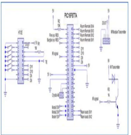
4.2.1 Transmitter remote control implementation
Both RF Module and IR systems are used to implement the remote control system. PIC16F877A is programmed to have 11 input ports and 6 output ports to implement the remote control. All of the inputs are connected together to the button switch to send a signal to PIC16F877A for the different operation in the system. For output port, 4 pins are used to send a parallel code to the RF Module encoder. Then transfer it to serial code and send it to the RF module transmitter unit. Also one port is used to send data to IR transmitter, and finally another port is used to connect it with led to make the indicator for sending data from PIC16F877A.
A mechanism for using input and output ports in the remote control, every port is related to a specific operation in the system. For the button switch and input port, the 11 button switch, divided into 2 parts in programming system, 4 of these switches is related to the room's receiver units, and the other 7 switches related to the central receiver unit. In 4 output ports that used to send parallel data to RF Module, we send a different code for every operation in the remote via 4 ports. This means that when any of the button switch is SET, PIC16F877A will send a code to the RF Module encoder. Finally, the port that connected to led is made to make an indicator for the user that the output signal is sent from remote control unit or not. Toggle system used in all four switch to enable the user to switch on/off the different loads using the same switch. When one of the four switches that related to room receiver unit is switched, PIC16F877A will send three outputs at the same time. The first output is sent to an IR transmitter as a pulse which has 38 KHz frequency. We make these pulses by making 1 logic level and another 0 logic, and both of them are divided into sub pulses to make the wanted frequency. PIC16F877A is used to generate this frequency.
Fig (e) Circuit Diagram For Remote Control Unit
The second output is sent to the RF module encoder, it's consist of four bits that send parallel to the encoder. For every switch of the 4 buttons, have a unique code, from this; we can control four loads in the room. The third output is sent to a led output device to make an indicator for sending the data from remote control. For any switching, PIC16F877A will send a pulse to the led.
Connection between remote control unit and central receiver unit in the house is made using only RF Module to enable the user to control the system in any place inside the house.
4.2.2 Central receiver unit implementation:
Fig (f) circuit diagram for central receiver unit
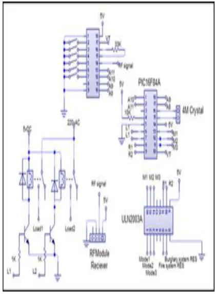
4.2.3 Room receiver unit implementation:
The main idea of load control unit is to deploy a room receiver unit in every room which is used to control the load. Each unit in the load control can control upto four loads in the room . Using both IR system and RF module we can confine the control limited to the room only because of using an IR system that operates by line of sight transmission inside the room. In the room receiver units we used PIC16F877A to receive four parallel bits from the RF module decoder after transfer the serial data from the RF module receiver. The different codes that received from the RF module will change inside the controller to 4 output lines with, connected to transistor and 5v relay for every load where the contact of the relay can connect with the load lines to switch the power that entered to it.
In the same time of switching the different load, PIC16F877A will send output signals to buzzer to make a sound as indicator about the change in the load condition; that means that every buzzer sound gives us a sense that the load is on or off.
An IR receiver output signal is connected to one of the coding pins of the RF module decoder. This pin will be activated when the IR signal reaches the room receiver unit, and in the same time the same pin in RF module encoder in remote control unit is connected as same way in the decoder IC
Fig (g) Circuit diagram for room receiver unit
5.
CONCLUSION
In this paper, I tried to complete the hardware part in which, LDR kit, power supply kit and relay kit, Driver kit are assembled together. In Lab-View Software the block diagram and front panel are designed with suitable requirement. By interfacing the both hardware and software I get the exact result after checking the three main conditions.
6.
REFERENCE
[1] Dr. Basil Hamed , “The Design and Implementation of Smart House Control Using Lab VIEW”, International Journal of Soft Computing and
Engineering (IJSCE), Volume-1, Issue-6, January 2012.
Application Made Real, Using Labview” ,
Undergraduate Academic Research Journal (UARJ), Volume-1, Issue-2, 2012.
[3] B V Sumangala & K Bhargava Ram, “Advantages of LabVIEW over Embedded System in Home Automations”, International Conference on
Advancement in Engineering Studies & Technology, July 2012.
[4] Guneet Kour, Jaswanti, “Labview Based Alarm Systems in Home”, UNIASCIT, Volume- 2, No 3, 2012.
[5] Rosslin John Robles and Tai-hoon Kim, “A Review on Security in Smart Home Development”,
International Journal of Advanced Science and Technology, Volume- 15, 2010.
[6] Lab VIEW user Manual, 2003 Edition, National Instruments.
[7] http://www.ni.com/labview
[8]
http://depts.washington.edu/dmgftp/publications/htm l/ smarthouse98-mdg.html
[9] Sleman, A.; Alafandi, M.; Moeller,”Integration of Wireless Fieldbus and Wired Fieldbus for Health Monitoring”; R.;Consumer Electronics, 2009. ICCE '09. Digest of Technical Papers International Conference on 10-14 Jan. 2009 Page(s):1 - 2
[10] Van Nguyen, T.; Jin Gook Kim; Deokjai Choi, "ISS: The Interactive Smart home Simulator," Advanced Communication Technology, 2009. ICACT 2009. 11th International Conference on , vol.03, no., pp.1828- 1833, 15-18 Feb. 2009
[11] Escoffier, C.; Bourcier, J.; Lalanda, P.; Jianqi Yu, "Towards a Home Application Server," Consumer Communications and Networking Conference, 2008. CCNC 2008. 5th IEEE, vol., no., pp.321-325, 10-12 Jan. 2008.
[12] Salvador, Z.; Jimeno, R.; Lafuente, A.; Larrea, M.; Abascal, J.;”Architecture for ubiquitous enviroments” Wireless And Mobile Computing, Networking And Communications, 2005. (WiMob'2005), IEEE International Conference on, Volume 4, 22-24 Aug. 2005 Page(s):90 - 97 Vol. 4.
[13] Patricio, G.; Gomes, L., "Smart house monitoring and actuating system development using
automatic code generation," Industrial Informatics, 2009. INDIN2009. 7th IEEE International Conference on, vol., no., pp.256-261, 23-26 June 2009
[14] LabVIEW for Everyone: Graphical Programming Made Easy and Fun, Jeffrey Travis, Jim Kring, Third Edition.
Prentice Hall Professional, 2007 ISBN-10: 0131856723.
[15] http://zone.ni.com/devzone/cda/pub/p/id/1141
[16] Chance Elliott, Vipin Vijayakumar, Wesley Zink, and Richard Hansen: National Instrument LabVIEW: A programming environment for laboratory automation and measurement, the association for Laboratory Automation, 2007.
[17] Bitter, Rick, Taqi Mohiuddin, and Matt Nawrocki “LabVIEW Advanced Programming Techniques “Boca Raton: CRC Press LLC, 2001