Review
1
Three Dimensional ZnO Hierarchical Nanostructures:
2
Solution Phase Synthesis and Applications
3
Xiaoliang Wang 1,*, Mashkoor Ahmad 2 and Hongyu Sun 3,*
4
1 College of Science, Hebei University of Science and Technology, Shijiazhuang 050018, PR China;
5
wxlsr@126.com (X. W.)
6
2 Nanomaterials Research Group, Physics Division, Pakistan Institute of Nuclear Science and Technology,
7
P.O. Nilore, Islamabad 44000, Pakistan; mashkoorahmad2003@yahoo.com (M. A.)
8
3 Department of Micro- and Nanotechnology, Technical University of Denmark, Kongens Lyngby 2800,
9
Denmark; hsun@nanotech.dtu.dk (H. S.)
10
* Correspondence: wxlsr@126.com; hsun@nanotech.dtu.dk; Tel.: +45-45 25 68 40 (H. S.)
11
Abstract: Zinc oxide (ZnO) nanostructures have been studied extensively in the past years due to
12
the novel electronic, photonic, mechanical and electrochemical properties. Recently, more attention
13
has been paid to assemble nanoscale building blocks into three dimensional (3D) complex
14
hierarchical structures, which not only inherit the excellent properties of the single building blocks
15
but also provide potential applications in the bottom-up fabrication of functional devices. This
16
review article focuses on 3D ZnO hierarchical nanostructures, and summarizes major advances in
17
the solution phase synthesis, applications in environment, and electrical/electrochemical devices.
18
We present the principles and growth mechanisms of ZnO nanostructures via different solution
19
methods, with an emphasis on rational control of the morphology and assembly. We then discuss
20
the applications of 3D ZnO hierarchical nanostructures in photocatalysis, field emission,
21
electrochemical sensor, and lithium ion batteries. Throughout the discussion, the relationship
22
between the device performance and the microstructures of 3D ZnO hierarchical nanostructures
23
will be highlighted. This review concludes with a personal perspective on the current challenges
24
and future researches.
25
Keywords: zinc oxide; hierarchical nanostructures; solution phase synthesis; photocatalysis; field
26
emission; sensor; lithium ion batteries
27
28
1. Introduction
29
Advanced nanomaterials which are earth abundant and environmentally compatible show the
30
potential to solve the serious energy and environment problems. As an important and widely used
31
wide bandgap (3.0-3.2 eV) oxide semiconductor, ZnO shows unique physical and chemical
32
properties [1]. The applications of ZnO materials range from room temperature nanolasers,
33
nanogenerators, solar cells, lithium ion batteries and photocatalysts.
34
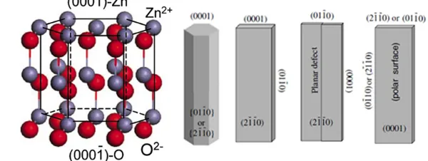
ZnO crystal shows the stable structure as hexagonal wurtzite under the condition of normal
35
temperature and atmospheric pressure. The crystal structure of ZnO can be viewed as a number of
36
alternating planes composed of tetrahedrally coordinated oxygen and zinc ions stacked alternately
37
along the [0001] direction (Figure 1). There are two important structural characteristics in wurtzite
38
ZnO, i.e., the absence of inversion symmetry of the positive and negative charge centers and polar
39
surfaces, which are the origin of piezoelectric properties and abundant 1D morphologies in the
40
synthesized ZnO nanostructures. In principle, the equilibrium morphology of a crystal is
41
determined by the standard Wulff construction, which dependents on the surface energy [2]. From
42
the viewpoint of decreasing the system total energy, low-index crystallographic faces prefer to be
43
exposed on the final crystallite as shown in Figure 1. Since the surface energy can be modified by
44
selective adsorption of additives or surfactants on specific planes, the morphology can be controlled
45
accordingly by adding suitable agents during the synthesis.
46
47
48
Figure 1. Crystal structure model of wurtzite ZnO, and typical morphologies of 1D ZnO
49
nanostructures with exposed facets.
50
Inspired by the size- or morphology-dependent properties or device performances, numerous
51
efforts have been devoted to the synthesis of ZnO nanostructures with 1D morphologies, such as
52
nanowires, nanobelts, nanorings, nanohelices and so on. Recently, more attention has been paid to
53
assemble low-dimensional nano-sized building blocks into three-dimensional (3D) complex
54
hierarchical structures [3]. Compared to mono-morphological structures, 3D ZnO hierarchical
55
structures usually exhibit high surface to volume ratios, a large accessible surface area and better
56
permeability. In addition, the hierarchical structures can increase the number of light traveling paths
57
and thereby facilitate light absorption. Finally, such 3D hierarchical structures not only inherit the
58
excellent properties of the single nano-sized building blocks but also provide potential applications
59
in the bottom-up fabrication of functional devices including photocatalysts, sensors and drug release
60
systems [4]. It is, therefore, important to develop facile approaches to synthesize 3D hierarchical
61
structures with controlled fashion.
62
63
64
Figure 2. Typical 3D ZnO hierarchical nanostructures and their applications as photocatalysts, field
65
electron emitters, electrochemical sensors, and electrodes for batteries.
66
Herein, we summarize the most recent progress in the synthesis of 3D ZnO hierarchical
67
nanostructures by using solution phase routes, and discuss the related applications. Firstly, typical
68
solution phase synthesis methods towards 3D ZnO hierarchical nanostructures are reviewed,
69
including direct precipitation, microemulsions, hydrothermal/solvothermal, sol-gel, electrochemical
70
deposition, and chemical bath deposition. The basic principles of the synthesis and main factors
71
that influence the structure and morphology of the products are analyzed. Then, different
72
photocatalysis, field emission, electrochemical sensors, and electrodes for lithium ion batteries
74
(Figure 2). Finally, current challenges and future outlooks of the synthesis and applications of 3D
75
ZnO hierarchical nanostructures are briefly outlined.
76
2. Solution Phase Synthesis of 3D ZnO Hierarchical Nanostructures
77
The above discussion shows that the hierarchical assembly in ZnO nanostructures are related
78
to the electronic/optical properties and thus a wide range of potential applications. So far, many
79
synthesis strategies based on physical (physical and chemical vapor deposition, laser ablation, ball
80
milling, lithographic, etc), chemical (gas phase reaction, various solution phase synthesis), or
81
biological methods have been well established to obtain 3D ZnO hierarchical nanostructures [5].
82
Comparing to other methods, solution phase route shows unique advantages, such as low cost (low
83
in energy consumption and equipment costs), scalability, and ease of handling. Most of the solution
84
phase reactions occur under mild condition with a relatively low temperature (< 200 oC). Therefore,
85
solution phase synthesis have attracted increasing interest. Typical solution phase synthesis
86
includes precipitation, microemulsions, hydrothermal/solvothermal, sol-gel, electrochemical
87
deposition, chemical bath deposition, and so on. There are several excellent reviews describing the
88
synthesis of ZnO nanostructures [6-9]. In this paper, we mainly focus on ZnO hierarchical
89
nanostructures synthesized by different solution phase methods.
90
2.1. Precipitation
91
In a typical precipitation process, different kinds of alkalis (NaOH, KOH, ammonium, urea,
92
hexamethylene tetramine (HMT), etc) and zinc sources (zinc salts, zinc foil, etc) are involved in the
93
reaction system (Figure 3a). A resultant precipitate is collected by filtration or centrifugation. The
94
morphology and assembly of the ZnO products can be controlled by adjusting the reaction
95
conditions, including the concentration of reacted solutions, temperature, time, and additives to
96
tune the reaction steps. Sepulveda-Guzman et al. [10] synthesized ubmicron ZnO arrays by a simple
97
one-step aqueous precipitation method with zinc nitrate (Zn(NO3)2) and sodium hydroxide (NaOH)
98
as the reagents. The effect of reaction temperature on the morphology change was studied.
99
Snowflake-like and flower-like morphologies were obtained at 60 oC and 70 oC. The ZnO arrays are
100
formed through self-aggregation process, and that such an oriented aggregation is enhanced by
101
increasing the reaction temperature. In another work, Oliveira and co-workers [11] systematically
102
investigated the influence of zinc salts (Zn(NO3)2·6H2O, zinc sulfate (ZnSO4·7H2O)), pH value,
103
temperature, additives (sodium sulfate, sodium dodecyl sulfate) on the final ZnO morphology and
104
size. The results show the importance of nucleation of nanometric primary particles followed by
105
oriented aggregation to produce uniform submicrometric particles.
106
It should be noted that ZnO is a typical amphoteric oxide, which can be etched in either acid or
107
alkali environment. The reaction between the zinc ions and alkaline ions results in the formation of
108
ZnO crystals. Meanwhile, the newly formed ZnO further reacts with alkaline until an equilibrium is
109
achieved. Thus, tuning the precipitation (growth) and in-situ etching provides a facile approach to
110
control the morphology of nanocrystals [12-14]. For example, Xi et al. [12] fabricated large-scale
111
arrays of highly oriented single-crystal ZnO nanotubes by an in-situ chemical etching of the ZnO
112
nanorods. Yang et al. have demonstrated a novel anisotropic etching methodology for the synthesis
113
of complex Ag nanoparticles shapes by controlling the concentrations of etching solution, and
114
highlighted their important applications as highly sensitive surface enhanced Raman spectroscopy
115
substrates [13]. In our previous studies [4], we reported a simple precipitation to synthesize ZnO 3D
116
hierarchical structures by using Zn(NO3)2·6H2O, Zn foil, and KOH as the zinc souce and alkalis.
117
Importantly, the morphology of the hierarchical structures can be simply selected by changing the
118
KOH concentrations. The morphology of the products are sheet, flower-like microsphere assembled
119
by nanosheets, flower-like microsphere assembled by nanoneedles, and flower-like microsphere
120
assembled by thinner nanoneedles when the concentration of KOH increased from 0.5 to 2, 4, and 8
121
M, respectively (Figure 4a). A possible formation mechanism based on preferential etching of KOH
122
further controlled by adding suitable capping agents that prefer to absorb on specific crystal planes,
124
making it possible to fine control over the morphology. Tian et al. [15] demonstrated that citrate
125
ions can selectively adsorb on the (001) surfaces of ZnO crystals and thus inhibit the growth along
126
<001> orientations. Based on these knowledge, they synthesized large arrays of oriented ZnO
127
nanorods with controlled aspect ratios and a series of complex morphologies. In our studies, we
128
combined the selective capping (citrate ions) and etching (KOH) together to capture the
129
intermediate of the morphology change, and proposed a possible formation mechanism based on
130
capping–etching competitive interactions (Figure 4b) [16]. The strategy can also be applicable to the
131
synthesis and modification of other materials by careful selecting suitable capping agents and
132
etchants.
133
134
135
Figure 3. Typical solution phase methods for the synthesis of 3D ZnO hierarchical nanostructures. (a)
136
precipitation, (b) microemulsions, (c) hydrothermal/solvothermal, (d) sol-gel, (e) electrochemical
137
deposition, and (f) chemical bath deposition.
138
139
Figure 4. Schematic illustration of the formation process of ZnO 3D hierarchical structures via the
140
combining of (a) growth and in-situ etching (reprinted from [4] with permission, Copyright The
141
Royal Society of Chemistry, 2012); (b) capping and etching (reprinted from [16] with permission,
142
Copyright The Royal Society of Chemistry, 2015).
143
2.2. Microemulsions
145
Materials synthesis via microemulsion is occurred in a stable mixed solution that contains
146
water, oil, and surfactant. Depending on the properties of immiscible liquid-liquid interface, the
147
formation of microemulsion can be in the form of oil-swollen micelles dispersed in water
148
(oil-in-water, or O/W) or the reverse case, i.e. water swollen micelles dispersed in oil (water-in-oil,
149
W/O) (Figure 3b). The two configurations are usually named as microemulsion and reverse
150
microemulsion, respectively [17]. The typical size of the microemulsion or reverse microemulsion is
151
samller than 100 nm, therefore, the microemulsions can be used as nanoreactors for materials
152
synthesis, which provides a bottom-up route to control the size and morphology by adjusting the
153
microemulsion properties. By studying the phase diagrams of oil-water-surfactant system
154
containing toluene, zinc acetate solution, cetyltrimethylammonium bromide and butanol, Lin et al.
155
obtained the desired size and shape of ZnO particles [18]. This study demonstrates the importance
156
of investigating the the intrinsic properties of this multi-liquid-phase system.
157
2.3. Hydrothermal and Solvothermal
158
Hydrothermal synthesis is referred to the materials synthesis by chemical reactions of
159
substances in a sealed heated aqueous solution above ambient temperature and pressure, while
160
solvothermal is very similar to the hydrothermal route except the precursor solution is usually
161
non-aqueous (Figure 3c) [19-21]. Well control over the hydrothermal/solvothermal synthetic
162
conditions is a key to the synthesis of ZnO nanomaterials with defined structure, morphology,
163
composition, and assembly. Typical control experimental parameters include reagents, solvent,
164
additives, filling degree, temperature, time, and so on [22, 23]. In addition, substrate is an important
165
and interesting parameter that can affect the ZnO morphology, especially the aligned ZnO
166
nanostructures. In a study, ZnO nanostructures on Zn foil was synthesized by hydrothermal
167
synthesis [24]. The morphology and assembly of ZnO arrays are dependent on the solvent
168
properties. Specifically, ZnO nanorod arrays and randomly scattered nanorods are obtained in the
169
mixed solvent containing ammonia aqueous solution (1%) and pure water, and pure water system,
170
respectively. Moreover, repetitive hydrothermal or solvothermal treatment can yield more complex
171
and hierarchical configurations. By employing this simple strategy, Ko et al. [25] synthesized high
172
density and long branched tree-like ZnO nanoforests. In a report of Joo et al. [26], single-crystalline
173
ZnO nanowires were grown on substrates with zinc oxide seed layers in aqueous solutions by
174
hydrothermal method. The effect of specific additives on the ZnO morphology was studied in detail.
175
The results show that the addition of positively charged complex ions (Cd, Cu, Mg, Ca) and
176
negatively charged complexes (Al, In, Ga) promote low and high aspect ratio growth of ZnO
177
nanostructures. They demonstrated that face-selective electrostatic crystal growth inhibition
178
mechanism governed this selective synthesis.
179
2.4. Sol-Gel Processing
180
The sol-gel process contains the formation of solid material from a solution by using a sol or a
181
gel as an intermediate step. The synthesis of metal oxide materials often involves controlled
182
hydrolysis and condensation of the alkoxide precursors or salts. Figure 3d illustrates the main steps
183
of preparation of metal oxides powder by the sol-gel process: (i) preparation of the precursor
184
solution; (ii) hydrolysis of the molecular precursor and polymerization via successive bimolecular
185
additions of ions, forming oxo-, hydroxyl, or aquabridges; (iii) condensation by dehydration; (iv)
186
solvent evaporation and organic compounds removal to form xerogel; and (v) heat treatment of the
187
xerogel to form powers. Properties of the final products, including the particle size, surface area,
188
crystallinity, and agglomeration, are highly dependent on the reactiuon parameters, especially the
189
precursors, solvents, additives, evaporation, drying, and post-treatment conditions [27]. Tseng et al.
190
[28] employed the sol-gel process to synthesize ZnO polycrystalline nanostructures using
191
Zn(CH3COO)2·2H2O as the zinc solute and different alcohols as solvents (glycol, glycerol, and
192
particles. The formation of thorn like ZnO nanostructures in sol-gel process was reported by Khan
194
and co-workers [29]. They further modified this method by mechanical stirring during the sol
195
generation, and found the agitation speed was a critical value in determining the size, aspect ratio
196
of the particles. Higher stirring speed is favorable for anisotropic growth of ZnO nanoparticles.
197
2.5. Electrochemical and Chemical Bath Deposition
198
Electrochemical deposition (ECD) and chemical bath deposition (CBD) methods are facile and
199
can produce materials or nanostructures that cannot be obtained by other deposition methods. CBD
200
process only requires suitable solution containers and substrate mounting devices (Figure 3e), while
201
for ECD method, additional power supplies, electrodes (counter electrode/CE, reference
202
electrode/RE) are necessary, and the substrate (working electrode/WE)must be conductive (Figure
203
3f). More importantly, the morphology and orientation of the deposited samples can be tuned by
204
controlling the reaction thermodynamics and kinetics, including solution properties, additives,
205
substrate, temperature, and electrochemical parameters (applied potential, current density, etc)
206
[30-35].
207
The synthesis of ZnO nanostructures via ECD process includes the reduction of precursor at
208
the electrode, the supersaturation at the vicinity of the electrode, and subsequent precipitation.
209
Theoretically, factors that affect any step should be considered to achieve the well control of final
210
structures. In this regard, Illy et al. [36] systematically studied the effect of various experimental
211
parameters (electrolyte concentration, pH value, reaction temperature, and overpotential) on the
212
morphology, thickness, transparency, roughness and crystallographic orientation of the ZnO
213
materials. They found that ZnO nanostructures with (002) preferential orientation and controlled
214
thickness can be grown by using optimized parameters, which are important for organic
215
photovoltaic applications. Different additives can either interact with the ions in the electrolyte,
216
absorb on specific sites on the deposited ZnO structure, or change the electrolyte itself (conductivity,
217
viscosity, etc), resulting in a different deposition pathways and thus final products. In a study by
218
Oekermann and co-workers [37], the addition of water soluble tetrasulfonated
219
metallophthalocyanines (TSPcMt), in which Mt = Zn(II), Al(III)[OH] or Si(IV)[OH], in the electrolyte
220
containing zinc nitrate yields completely different morphology and assembly, which is ascribed to
221
the preferential adsorption of the additive molecules onto the crystal planes of ZnO. The
222
morphology and assembly of the depositions can also be controlled by substrate, for example
223
patterned or flexible ZnO hierarchical nanostructures can be obtained by applying corresponding
224
substrates [38].
225
Synthesis of ZnO nanostructures via CBD is based on a direct chemical reaction involving
226
dissolved zinc ions and oxygen precursors in the solution. Different from ECD where the
227
deposition only occurs on the conductive substrate, the growth of ZnO in CBD process can take
228
place either in the solution or on the substrate surface. The morphology and assembly of ZnO
229
products can also be controlled by the solution, additives, substrate, and so on [39].
230
The above discussed different solution phase synthesis methods can be combined together or
231
with other treatments, such as microwave heating, sonochemistry, etc, to achieve even more
232
complex and useful hierarchical nanostructures with useful applications. For example, sol-gel
233
processing or microemulsions is often employed with hydrothermal/solvothermal treatment to
234
prepare various nanostructures [40]. The pre-synthesized ZnO nanostructures via hydrothermal or
235
ECD methods can be further etched to form needle or tube arrays [41]. The assembly of ZnO
236
architectures can be tuned by means of ECD via deformation and coalescence of soft colloidal
237
templates in reverse microemulsion [42]. In a word, solution phase synthesis provides plenty of
238
room to control and optimize hierarchical ZnO architectures for diverse applications.
239
240
3. Applications of 3D ZnO Hierarchical Nanostructures
241
3D ZnO hierarchical nanostructures show unique advantages of high surface area, porous
242
nanostructures possess improved physical/chemical properties, such as enhanced light harvesting,
244
increased reaction sites, and improved electron and ion transportation, which are highly needed for
245
optical, electrical, and electrochemical applications. In this paper, we will review the most recent
246
progress in the research activities on 3D ZnO hierarchical nanostructures used for photocatalysis,
247
field emission, electrochemical sensors, and electrodes for lithium ion batteries.
248
3.1. Photocatalysis
249
ZnO nanostructures have attracted much attention in the fields of photocatalysis, including
250
photocatalytic degradation of organic contaminants, photocatalytic water splitting, and so on, due
251
to the notable merits such as nontoxicity, biological compatibility, and universality. Typical steps
252
involved in heterogeneous photocatalysis process are as follows (Figure 5) [43]: (1) light absorption;
253
(2) the generation and separation of photoexcited electrons and holes; (3) the migration, transport
254
and recombination of carriers; and (4) surface electrocatalytic reduction and oxidation reactions. The
255
overall catalysis efficiency is related to the cumulative effects of these consecutive steps. For ZnO
256
photocatalysts, the activity is limited by the intrinsic wide bandgap (3.0-3.2 eV) and the high
257
electron-hole recombination rate, which can be tuned by optimizing the structural parameters of the
258
photocatalysts, such as size, morphology, assembly, specific surface area, and the defect density [44].
259
Compared to the 0D, 1D, or 2D counterparts, 3D ZnO hierarchical nanostructures show advantages
260
of high surface area and porous structures, enhanced light harvesting, and synergistic effects
261
between the nano building blocks. All these characters are beneficial for the photocatalysis
262
enhancement.
263
264
265
Figure 5. Schematic illustration on the photocatalytic processes in ZnO (reprinted and modified from
266
[43] with permission, Copyright Continental Press, 2016).
267
The comparison of the photodegradation of organic dye Rhodamine B (RhB) under
268
UV-irradiation with different 3D ZnO hierarchical nanostructures yielded by facile solution phase
269
method is shown in (Figure 6a, b) [4]. Under the same experimental conditions, the relative
270
photocatalytic activity is thin needle flowers > needle flowers > sheet flowers > nanosheets. The
271
significant improvement in the photocatalytic activity of the thin needle flowers structure can be
272
attributed to the following reasons: (1) optical quality and special structural features; (2) the large
273
active surface area and interspaces of the flower structure, which facilitate the diffusion and mass
274
transportation of RhB molecules and hydroxyl radicals; (3) the improved efficiency of electron–hole
275
separation. The morphology of ZnO nanostructures dependent photocatalysis is later demonstrated
276
in the degradation of methylene blue in aqueous solution [45]. By coupling the strategies of
277
elemental doping [46], defect engineering [47], modifying the surface with visible light active
278
materials [48] or plasmonic-metal nanostructures (Ag, Pt, Au, etc) [49], the photodegradation
279
evaluated photocatalytic performance of ZnO needle flowers and Au nanoparticles/ZnO needle
281
flowers composite (Au/ZnO) by degradating organic dye RhB under UV irradiation (Figure 6c-e)
282
[50]. The pure ZnO showed observable photocatalytic activity but with rather slow kinetics. Only
283
~60% of the RhB was decomposed within 90 min. In contrast, when the Au/ZnO composites were
284
applied as the photocatalyst, a significant synergistic enhancement effect was observed, i.e., RhB was
285
decomposed thoroughly within 90 min. The Au nanoparticles enhanced photodegradation is also
286
observed in ZnO sheet flowers. In these studies, besides the hierarchical morphology of ZnO
287
nanostructures, the improvement of photocatalytic properties can be ascribed to the presence of
288
noble metal nanoparticles. (1) The light absorption is increased due to the strong surface plasmon
289
resonance of the noble metal nanoparticles; (2) the efficiency of charge separation of the
290
photo-generated electron-hole pairs is increased due to the strong electronic interaction between
291
strong electronic interaction and ZnO.
292
293
294
Figure 6. Photocatalytic degradation of RhB via (a, b) 3D ZnO hierarchical nanostructures with
295
different morphologies (reprinted from [4] with permission, Copyright The Royal Society of
296
Chemistry, 2012); (c-d) ZnO needle flowers and Au nanoparticles/ZnO needle flowers composite
297
(reprinted from [50] with permission, Copyright The Royal Society of Chemistry, 2011).
298
The above routes to improve the degradation properties in ZnO hierarchical photocatalysts can
299
also be applied to photosplit water to generate hydrogen. For example, elemental doping and defect
300
engineering are effective to narrow the bandgap of ZnO materials, which results in an extension of
301
light absorption range from UV into visible light range, while generating interface structures by
302
depositing plasmonic noble metals separates photogenerated carriers, improves visible and
303
near-infrared photo-absorption, and thus achieves high-performance photocatalytic hydrogen
304
evolution.
305
3.2. Field Emission
306
Field emission devices show several advantages, such as the resistance to temperature
307
fluctuation and radiation, less power consumption, low thermionic noise, low energy spread,
308
miniature volume and nonlinear, exponential current–voltage (I-V) relationship in which a small
309
variation in the voltage results in a large change in the emission current instantaneously [51].
310
Theoretical calculations show that the external filed induces a decrease of the surface barrier height
311
by a value of ∆Ф ~ 3.8 F1/2 (for Ф in eV and F in V/Å) (Figure 7a), and the field is off the order of ~109
312
V/m. If the emitter surface is sharp configuration as shown in Figure 7b, electrons can be extracted at
313
a considerably lower applied field. The relationship between the field emission current density (J)
314
and the applied electric field (E) is described by Fowler-Nordheim (FN) equation:
315
(
2 2 Φ)
exp[
− Φ32( )−1]
= A E B E
and second F-N constants, Ф is the work function, and β is the field enhancement factor, which
317
reflects the the magnitude of electric field at the emitting surface. The emission current density at a
318
constant cathode-anode distance is strongly dependent on the work function Ф and the field
319
enhancement factor β that is related to geometric configuration of the emitter, crystal structure,
320
conductivity, and so on.
321
322
323
Figure 7. (a) Potential energy of an electron near the cathode surface (reprinted from [52] with
324
permission, Copyright American Vacuum Society, 2007); (b) Illustration of field electron emission
325
from a tip (reprinted from [53] with permission, Copyright Elsevier B.V., 2004).
326
With inherent properties of thermally stable and oxidation resistant, ZnO nanostructures show
327
potential to be a good candidate for field emission. Moreover, a variety of ZnO nanostructures can
328
be synthesized by facile solution phase methods as discussed above, which not only reduce the cost,
329
but also make it possible to fabricate flexible field emission devices based on polymer or other metal
330
substrate materials [54, 55].
331
Field emission studies on ZnO nanorod arrays synthesized on zinc foils by the solvothermal
332
route are presented by Dev et al [56]. The effect of solvothermal parameters including the solvent
333
(distilled water and ethylenediamine), temperature, and time on the morphology and field emission
334
properties of ZnO nanostructures are studied. It was observed that with the increase in
335
ethylenediamine concentrations the alignment of the nanorods gets better, corresponding to the
336
increasement of field enhancement factor from 850 to 1044. ZnO nanotube arrays were prepared by
337
hydrothermal reaction in ammonia and zinc chloride solutions by Wei et al [57]. The turn-on field of
338
the ZnO nanotube arrays was extrapolated to be about 7.0 Vm-1 at a current density of 0.1 Acm-2, the
339
emission current densities reached 1 mAcm-2 at a bias field of 17.8 Vm-1, and the field enhancement
340
factor was estimated to be 910. Cao et al. [58] reported the field emission of wafer-scale ZnO
341
nanoneedle arrays synthesized by template-free electrochemical deposition method. The field
342
enhancement factor of the ZnO nanoneedle arrays was 657 with a working distance of 250 μm
343
between the cathode and anode. In our studies [59], we compared the field emission properties of
344
ZnO nanowire arrays with flat ends and nanoneedle arrays with sharp ends (Figure 8a). The ZnO
345
nanowires were synthesized by hydrothermal method at 70 oC. Then solution etching was employed
346
to form ZnO nanoneedles at room temperature. The turn-on electronic fields of ZnO nanoneedles
347
and nanowires are 2.7 and 5.3 V μm-1 at a current density of 10 μA cm-2. The threshold electronic
348
fields, which defined as the field value at the emission current density J of 0.1 mA cm-2, of ZnO
349
nanoneedles and nanowires are 3.9 and 6.1 V μm-1, respectively (Figure 8b). The field enhancement
350
factors were estimated to be 4939.3 for ZnO nanoneedles and 1423.6 for ZnO nanowires (Figure 8c).
351
In addition, there is no obvious degradation of the current density, demonstrating the excellent
352
emission stability of the ZnO array materials (Figure 8d). This study highlights the important effect
353
of emitter geometry on the field emission.
354
356
Figure 8. The comparison of field emission properties of ZnO nanowires with flat ends and
357
nanoneedles with sharp ends. (a) TEM images; (b) J-E curves; (c) FN plots; (d) stability of the
358
emission current density under a constant electric field of 6.0 Vμm-1 (reprinted from [59] with
359
permission, Copyright Elsevier B.V., 2017).
360
Besides sample geometry, intrinsic electric conductivity in ZnO material also influences the
361
field emission properties. Using a simple solution reduction method, oxygen-deficient ZnO nanorod
362
arrays were synthesized by Su et al [60]. The concentration of oxygen vacancies can be effectively
363
controlled by adjusting the reduction temperature ranging from 30 -110 oC, resulting in a controlled
364
tailoring of the band structure of the ZnO. The final oxygen-deficient ZnO nanorod arrays with
365
optimized topography show excellent field emission properties, the threshold electronic field was as
366
low as 0.67 Vμm-1, the field enhancement factor was as large as 64601, the stability was also favorable.
367
In addition, doping with metal [61] or non-metal elements [62] through facile solution phase
368
methods is also an effective method to improve the field emission properties of ZnO nanostructures.
369
Doping induced conductivity enhancement and electron increasement in the conduction band are
370
the possible reasons for the emission properties improvement.
371
3.3. Electrochemical Sensors
372
Continuous monitoring biological molecules and metal ions has attracted much interest due to
373
the significant use in biotechnology, medicines, food and processing industry, and as a valuable
374
biological marker for many oxidative biological reactions. In this regard, electrochemical sensors
375
show unique advantages of high sensitivity, wide range of detection, real-time monitoring, ease of
376
fabrication and control, reproducibility, and low cost, which can not be simultaneously achieved by
377
other techniques, such as radioisotope tracing and nuclear magnetic resonance. The principle of
378
electrochemical sensors is based on electroanalytical chemistry techniques in which quantitative
379
investigating sensing is made by varying the potential and measuring the resulting current as an
380
analyte reacts electrochemically with the working electrodes surface (nanostructures modified glass
381
carbon electrode/GCE, Figure 9). The frequently used electrochemical techniques employed in
382
sensors include cyclic voltammetry (CV), linear scan voltammograms (LSV), differential pulse
383
voltammetry (DPV), electrochemical impedance spectroscopy (EIS), and so on.
384
Thanks to the biocompatible and nontoxic nature and high sensitivity to chemical species, ZnO
385
nanostructures have been intensively studied as different kinds of electrochemical sensors to
386
monitor important biological molecules and metal ions in organism, typically include glucose,
387
dopamine, uric acid, L-lactic acid, L-Cysteine, hydrogen peroxide, potassium, sodium, calcium,
388
nanostructures based electrochemical sensors generally show good sensitivity, low detection limit,
390
long-term stability, and repeatability.
391
392
393
Figure 9. Schematic illustration of the electrochemical sensor testing.
394
Yang et al. [63] prepared ordered single-crystal ZnO nanotube arrays on indium-doped tin
395
oxide coated glass by combining electrochemical deposition and subsequent chemical etching
396
methods. The samples were used as a working electrode to fabricate an enzyme-based glucose
397
biosensor, which exhibited high sensitivity of 30.85 μA cm-2 mM-1 at an applied potential of + 0.8 V
398
vs. SCE, wide linear calibration ranges from 10 μM to 4.2 mM, and a low limit of detection at 10 μM
399
for sensing of glucose. We studied electrochemical sensing of hydrogen peroxide by using noble
400
metal nanoparticle-functionalized ZnO nanoflowers. Firstly, the hierarchical flower-like ZnO
401
structures were synthesized by a co-precipitation method in a solution containing Zn (NO3)2·6H2O
402
and KOH. Au or Ag nanoparticles were decorated on the surface of ZnO nanoflowers by subsequent
403
hydrothermal treatment. Au/ZnO, Ag/ZnO and bare ZnO nanostructures modified GCE were
404
fabricated and used as H2O2 sensors. The electrodes were tested in 0.05 M Phosphate buffered saline
405
at pH = 7.2 with a platinum counter electrode and a saturated calomel electrode (SCE) reference
406
electrode. CV results show that the electrochemical oxidation of H2O2 started at about -0.68 to -0.1 V
407
versus SCE (Figure 10a), and the CV response for Ag/ZnO electrode was much higher than Au/ZnO
408
and bars ZnO electrodes. In addition, the Ag/ZnO electrode also exhibited rapid and sensitive
409
response to the change in concentration of H2O2 and the amperometric current is noticeably
410
increased upon successive addition of H2O2 (Figure 10b). The linear range of calibration curve for
411
these modified electrodes was from 1 to 20 μM (correction factor, R = -0.998) with a low limit of
412
detection (LOD) of about -2.5 μM (Figure 10c). The sensitivity of the H2O2 sensor for Ag/ZnO
413
modified electrode is 50.8 μA cm-2μM-1, which is much higher than that of Au/ZnO and bare ZnO
414
electrodes. Stability test showed that Ag/ZnO modified electrode was more stable as compared to
415
Au/ZnO and bare ZnO showing higher value of current with steady state current loss of 1.5 % after
416
300 s (Figure 10d). This work demonstrated that noble metal-integrated ZnO nanostructures
417
provided a new platform for applications in designing enzymeless biosensors. By decorating ZnO
418
nanostructures with optimized alloy clusters, the electrochemical activity can be further improved
419
[64].
420
Due to the mild condition of solution phase synthesis, ZnO nanostructures can be directly grew
421
on a wide range of flexible and conductive substrates, making it possible to fabricate free-standing
422
and flexible electrochemical sensors. For example, ZnO nanorods were uniformly anchored on the
423
surface of carbon cloth directly by a simple hydrothermal method [65]. The products were directly
424
used a electrode for the simultaneous determination of dihydroxybenzene isomers. The electrodes
425
showed good electrochemical stability, high sensitivity, and high selectivity. The linear ranges of
426
concentration for hydroquinone, catechol, and resorcinol were 2–30, 2–45, and 2–385 μM,
427
429
430
Figure 10. (a) Cyclic voltammograms of bare and modified GCE with pure ZnO, Au/ZnO, and
431
Ag/ZnO in the absence of H2O2 and in the presence of H2O2; (b) amperometric response of three
432
modified GCE at constant voltage of -0.45 V with successive addition of 1 μM H2O2 in 0.05 M PBS
433
under stirring; (c) corresponding calibration curves of the three modified electrodes and (d) stability
434
plot of the three modified GCE at constant potential of -0.45 V in the presence of 1 μM H2O2
435
(reprinted from [66] with permission, Copyright Springer Science+Business Media Dordrecht, 2016).
436
3.4. Lithium Ion Batteries
437
With a growing world population and increasing industrialization, energy and environment
438
become the two main factors that restrict the society sustainability. It is thus of urgent need to
439
develop renewable energy conversion and storage techniques. Lithium ion batteries are one of the
440
most important energy storage devices, which dominate the market of portable electronic devices,
441
and also show potential in hybrid/electric vehicles. Typical lithium ion batteries system mainly
442
includes anode, cathode, electrolyte, and separator, of which active materials used in both electrodes
443
play pivotal roles in determining the overall performance of batteries. For example, the specific
444
capacity of graphite anode in current commercial lithium ion batteries is as low as 372 mAhg-1,
445
which is insufficient for many applications. Searching for high-performance electrode materials
446
remains one of the most important focus in battery community. Among many potential electrode
447
candidates, ZnO nanostructures have attracted much attention due to the abundance of raw
448
materials, environmental benignity as well as facile synthesis [67-71]. In principle, the reaction
449
between lithium and ZnO anodes is occurred through the so-called mechanism of “conversion
450
reaction”. During lithiation, ZnO anode undergoes a conversion reaction to form Li2O embedded
451
with nanosized metallic zinc clusters. This step is followed by an alloying reaction between lithium
452
and the formed Zn NPs. The reaction processes are described as the following equations: ZnO + 2Li+
453
+ 2e- Zn + Li2O (conversion step); Zn + Li+ + e- LiZn (alloying step), which yields a higher
454
theoretical capacity (987 mAhg-1) than that of graphite [72-74].
455
However, the practical using of ZnO based anodes mainly suffer from low Columbic efficiency
456
(especially in the first cycle), severe capacity fading, and poor electrochemical kinetics [75,76]. Firstly,
457
the conversion step in the lithiation reaction represents the largely irreversible reduction process of
458
ZnO to metallic Zn. This irreversible chemical transformation is partly responsible for the large
459
initial irreversible capacity loss. Secondly, the alloying step is accompanied by a large volume
460
change (~228%) upon cycling, which results in material pulverization, electrode failure, and thus
461
rapid capacity fading. The volume change of the anodes also results in the formation of unstable
462
Thirdly, the low intrinsic electronic conductivity of ZnO materials causes moderate lithium ion
464
diffusion coefficient and limits the high-rate applications. To enhance the lithium storage properties
465
of ZnO anodes, the construction of 3D ZnO hierarchical nanostructures with proper morphology,
466
composition, and assembly has been proven to be an effective approach to overcome the above
467
limitations. (1) Capacity. Compared to the corresponding nanobuilding blocks, hierarchical
468
structures possess larger surface area, which increases the contact area between electrode and
469
electrolyte and thus the number of active sites for electrode reactions with lithium ions. In addition,
470
the hierarchical electrodes can lead to new lithium storage mechanisms, such as surface, interface,
471
and nanopore storage, which lead to excess capacity. (2) Stability. The low dimensional ZnO
472
nanobuilding blocks have high mechanical strength, more resistance to mechanical damage, and can
473
be engineered to allow volume change, and the assembled hierarchical structures can also prevent
474
the possible agglomeration during the continuous cycling. Both are essential to ensure the structural
475
integrity of the electrodes and long term stability. (3) Rate performance. The rate of battery operation
476
is related to the solid-state diffusion of lithium ions in the electrodes, which can be reduced in the
477
nanoscale electrodes.
478
The assembly of ZnO hierarchical nanostructures show great influence on the battery
479
performance. Zhang et al [77]. synthesized ZnO nanostructures with different morphology by a
480
facile hydrothermal and subsequent annealing treatment. The ZnO particles anode delivers the
481
largest initial discharge capacity of 1815.8 mAhg-1, and a reversible charge capacity of 870.0 mAhg-1
482
at the current density of 50 mAg-1, while cabbage-like ZnO nanosheets electrode displays better
483
cycling stability. In other work, ZnO nanorod arrays with dandelion-like morphology were grown
484
on copper substrates by a hydrothermal synthesis method [66]. The samples can be directly used as
485
electrodes without any additives or binders. Cycling performance was performed at a current
486
density of 0.1 mAcm-2. The charge capacity of the dandelion-like ZnO electrode decreases to 596, 481
487
and 419 mAhg-1 in the second, third and fifth cycle, respectively. The ZnO arrays keep a capacity
488
larger than 310 mAhg-1 even after 40 cycles, which is about 4 times higher than the stabilized
489
capacity of the bulk ZnO electrode. The unique dandelion-like binary-structure played an important
490
role in the electrochemical performance of the array electrodes.
491
Besides the architecture design, the electrochemical properties of ZnO anodes can further be
492
improved by composting with an electronically conductive agents (such as carbon nanofibers,
493
carbon nanotubes, graphene, metals, metal compounds and so on) [78-80]. Those additives can not
494
only enhance the conductivity of the electrodes but also modify the chemistry at the
495
electrode/electrolyte interface. Therefore, 3D ZnO hierarchical nanostructures with suitable surface
496
or interface composition modification show unique advantageous as improved lithium storage
497
properties. In our previous studies, we synthesized hierarchical flower-like ZnO nanostructure by a
498
facile solution phase approach. Au nanoparticles were functionalized on the surface of ZnO by
499
subsequent electrochemical deposition treatment. The diameter of the pristine ZnO microflower is
500
about 6-10 μm, and the length of an individual nanoneedle varies by 2-3 μm (Figure 11a). After
501
electrodeposition, Au nanoparticles with an average diameter of 4-6 nm are decorated on the surface
502
of each ZnO nanoneedle (Figure 11b,c). Comparing to the bare ZnO material, the Au-ZnO hybrid
503
hierarchical structures possess large specific surface area, abundant void spaces, stable structure and
504
strong electronic interaction between Au nanoparticles and ZnO. Those structural characters are
505
beneficial for lithium storage enhancement. The initial discharge and charge capacity of Au-ZnO
506
electrode are 1280 and 660 mAhg-1, respectively, yielding a Coulombic efficiency of 79% (Figure 11d).
507
In comparison, the initial discharge and charge capacity of pure ZnO electrode are 958 and 590
508
mAhg-1, respectively (Figure 11e). The initial Coulombic efficiency of ZnO electrode is 52%, which is
509
27% lower than that of the Au–ZnO hybrids electrode. The stability test results show that the charge
510
capacity of the Au–ZnO electrode decreases to 519 and 485 mAhg-1 after the second and third cycle,
511
and stabilizes at 392 mAhg-1 after 50 cycles (Figure 11f). In contrast, the capacity of the ZnO electrode
512
decays rapidly to 252 mAhg-1 (Figure 11f). The better lithium storage properties, including improved
513
capacity and cycle life of the Au–ZnO electrode can be attributed to the Au nanoparticles, which act
514
to the strong electronic interaction between Au nanoparticles and ZnO, electron can easily reach at
516
all the position where lithium ions intercalation takes place. This feature is very important when the
517
battery is cycled at high current density.
518
519
520
Figure 11. (a-c) Electron microscopy images and (d-f) lithium storage properties of the ZnO needle
521
flowers and Au nanoparticles/ZnO needle flowers composite (reprinted from [50] with permission,
522
Copyright The Royal Society of Chemistry, 2011).
523
524
Figure 12. (a) Schematic illustrating the synthesis procedures of ZnO@ZnO QDs/C core-shell
525
nanorod arrays on carbon cloth; (b, c) TEM and HRTEM images; (d, e) lithium storage properties of
526
ZnO@ZnO QDs/C core-shell structures (reprinted from [84] with permission, Copyright
527
WILEY-VCH Verlag GmbH & Co. KGaA, Weinheim, 2015).
528
Anchoring ZnO nanostructures on various carbon materials, such as graphite, mesoporous
529
carbon, mesoporous carbon bubble, hierarchical porous carbon, vertically aligned graphene, and
530
graphene aerogels, also facilitates the electron and lithium ion transport during charge/discharge
531
cycles [81-83]. Those composite anodes show improved lithium storage properties, especially high
532
rate capacity, which are highly dependent on the strong interaction between ZnO and carbon
533
nanostructures. To strengthen this adhesion, one strategy is in-situ formation carbon modification
534
example, Zhang and co-workers designed a facile and scalable strategy to synthesize integrated,
536
binder-free, and lightweight ZnO nanoarray-based electrode as shown in Figure 12a [84]. Firstly,
537
aligned and ordered ZnO nanorods were grown on carbon cloth via low temperature solution
538
deposition method. The ZnO nanorods were then served as the template as well as the Zn source to
539
induce the formation of zeolitic imidazolate frameworks-8 (ZIF-8), a typical metal-organic
540
framework, on the surface of ZnO nanorods (Figure 12b). Finally, unique ZnO@ZnO QDs/C
541
core–shell nanorod arrays were obtained by thermal treatment in N2. Structure studies show that the
542
shell of each nanorod is constituted by amorphous carbon framework and ultrafine ZnO quantum
543
dots (Figure 12c), resulting in a stronger adhesive force between carbon and the active ZnO materials,
544
which is important to accelerate the charge transfer in the electrode. Benefit from this structure
545
design, the resultant ZnO@ZnO QDs/C anode not only exhibits remarkable cycling performance
546
(Figure 12d), but also provides a remarkable rate capability, i.e. a reversible capability of 1055, 913,
547
762, 591, and 530 mAhg-1 at the current density of 100, 200, 400, 800, and 1000 mAg-1 (Figure 12e).
548
It is worth mentioning that the ZnO nanostructures can also be used as anodes for sodium ion
549
batteries [85,86], which are important complementarities of current lithium ion batteries. Due to the
550
fact that sodium chemistry is similar with the case of lithium, the established electrode-design
551
strategies for ZnO materials in lithium ion batteries system can be transferred to and expedite the
552
sodium ion battery studies.
553
4. Conclusions and Perspective
554
Recent years witness explosive research and development efforts on ZnO materials, ranging
555
from facile synthesis to advanced characterizations and device applications. 3D ZnO hierarchical
556
nanomaterials possess high surface area with porous structures, facilitate multiple physical and
557
chemical processes. In addition, the hierarchical materials not only inherit the excellent properties of
558
an individual nanostructure but also generate new properties due to the interactions between the
559
nano building blocks. Therefore 3D ZnO hierarchical nanostructures provide a wide range of
560
applications. This review article summarized the main progress in the synthesis of 3D ZnO
561
hierarchical nanostructures via different solution phase methods, such as precipitation,
562
microemulsions, hydrothermal/solvothermal, sol-gel, electrochemical deposition, and chemical bath
563
deposition. In each method, the synthesis principle, factors that affect the final structure and
564
morphology, and typical examples are briefly discussed. Then the applications of the 3D
565
hierarchical architectures in the fields of photocatalysis, field emission, electrochemical sensors, and
566
lithium ion batteries are analyzed, especially the effect of hierarchical morphology on the
567
performance are evaluated. Despite these impressive advances, several challenges still remain.
568
(1) Although great success has been made in the controllable synthesis of 3D ZnO hierarchical
569
architectures, there is still room for improvement in terms of quality and scale of the products.
570
Moreover, new synthesis methods also provide opportunities to explore novel morphology and
571
understand the formation mechanism of the nanostructures.
572
(2) Besides the hierarchical architectures, the device performance is also related to the size,
573
composition and defects of ZnO nanostructures. Coupling the 3D nanostructures with the ability of
574
fine control over geometry and chemistry can further optimize the chemical and physical properties.
575
(3) Direct study the dynamic morphological and chemical evolution of ZnO nanostructures
576
during the practical applications is of significance to study the performance degradation and
577
develop strategies to improve the stability.
578
Acknowledgments: This work was financially supported by the National Natural Science Foundation of China
579
(Grants No. 51401114, 51701063).
580
Conflicts of Interest: The authors declare no conflict of interest.
581
References
582
1. Sun, Y.; Chen, L.; Bao, Y.; Zhang, Y.; Wang, J.; Fu, M.; Wu, J.; Ye, D. The applications of morphology
583
2. Baruah, S.; Dutta, J. Hydrothermal growth of ZnO nanostructures. Sci. Technol. Adv. Mater. 2009, 10,
585
013001/1-18.
586
3. Burke-Govey, C. P.; Plank, N. O. V. Review of hydrothermal ZnO nanowires: Toward FET applications. J.
587
Vac. Sci. Technol., B 2013, 31, 06F101/1-12.
588
4. Sun, H.; Yu, Y.; Luo, J.; Ahmad, M.; Zhu, J. Morphology-controlled synthesis of ZnO 3D hierarchical
589
structures and their photocatalytic performance. CrystEngComm 2012, 14, 8626-8632.
590
5. Kołodziejczak-Radzimska, A.; Jesionowski, T. Zinc oxide—from synthesis to application: a review.
591
Materials 2014, 7, 2833–2881.
592
6. Zhang, Y.; Ram, M. K.; Stefanakos, E. K.; Goswami, D. Y. Synthesis, characterization, and applications of
593
ZnO nanowires. J. Nanomater. 2012, 2012, 1–22.
594
7. Naveed Ul Haq, A.; Nadhman, A.; Ullah, I.; Mustafa, G.; Yasinzai, M.; Khan, I. Synthesis Approaches of
595
Zinc Oxide Nanoparticles: The Dilemma of Ecotoxicity. J. Nanomater. 2017, 2017, 1–14.
596
8. Cargnello, M.; Gordon, T. R.; Murray, C. B. Solution-phase synthesis of titanium dioxide nanoparticles and
597
nanocrystals. Chem. Rev. 2014, 114, 9319–9345.
598
9. Znaidi, L. Sol–gel-deposited ZnO thin films: a review. Mater. Sci. Eng. B 2010, 174, 18–30.
599
10. Sepulveda-Guzman, S.; Reeja-Jayan, B.; de la Rosa, E.; Torres-Castro, A.; Gonzalez-Gonzalez, V.;
600
Jose-Yacaman, M. Synthesis of assembled ZnO structures by precipitation method in aqueous media.
601
Mater. Chem. Phys. 2009, 115, 172–178.
602
11. Oliveira, A. P. A.; Hochepied, J.-F.; Grillon, F.; Berger, M.-H. Controlled precipitation of zinc oxide
603
particles at room temperature. Chem. Mater. 2003, 15, 3202–3207.
604
12. Xi, Y.; Song, J.; Xu, S.; Yang, R.; Gao, Z.; Hu, C.; Wang, Z. L. Growth of ZnO nanotube arrays and nanotube
605
based piezoelectric nanogenerators. J. Mater. Chem. 2009, 19, 9260–9264.
606
13. Mulvihill, M. J.; Ling, X. Y.; Henzie, J.; Yang, P. Anisotropic etching of silver nanoparticles for plasmonic
607
structures capable of single-particle SERS. J. Am. Chem. Soc. 2010, 132, 268–274.
608
14. Li, F.; Ding, Y.; Gao, P.; Xin, X.; Wang, Z. L. Single-crystal hexagonal disks and rings of ZnO:
609
low-temperature, large-scale synthesis and growth mechanism. Angew. Chem. Int. Ed. 2004, 43, 5238–5242.
610
15. Tian, Z. R.; Voigt, J. A.; Liu, J.; Mckenzie, B.; Mcdermott, M. J.; Rodriguez, M. A.; Konishi, H.; Xu, H.
611
Complex and oriented ZnO nanostructures. Nat. Mater. 2003, 2, 821–826.
612
16. Mujtaba, J.; Sun, H.; Fang, F.; Ahmad, M.; Zhu, J. Fine control over the morphology and photocatalytic
613
activity of 3D ZnO hierarchical nanostructures: capping vs. etching. RSC Adv. 2015, 5, 56232–56238.
614
17. Malik, M. A.; Wani, M. Y.; Hashim, M. A. Microemulsion method: A novel route to synthesize organic and
615
inorganic nanomaterials. Arabian J. Chem. 2012, 5, 397–417.
616
18. Lin, J.-C.; Lee, C.-P.; Ho, K.-C. Zinc oxide synthesis via a microemulsion technique: morphology control
617
with application to dye-sensitized solar cells. J. Mater. Chem. 2012, 22, 1270–1273.
618
19. Demazeau, G. Solvothermal reactions: an original route for the synthesis of novel materials. J. Mater. Sci.
619
2008, 43, 2104–2114.
620
20. Demazeau, G. Solvothermal processes: definition, key factors governing the involved chemical reactions
621
and new trends. Zeitschrift für Naturforschung B 2014, 65, 999–1006.
622
21. Feng, S.; Xu, R. New materials in hydrothermal synthesis. Acc. Chem. Res. 2001, 34, 239–247.
623
22. Shi, W.; Song, S.; Zhang, H. Hydrothermal synthetic strategies of inorganic semiconducting
624
nanostructures. Chem. Soc. Rev. 2013, 42, 5714–5743.
625
23. Hayashi, H.; Hakuta, Y. Hydrothermal synthesis of metal oxide nanoparticles in supercritical water.
626
Materials 2010, 3, 3794–3817.
627
24. Yang, H.; Song, Y.; Li, L.; Ma, J.; Chen, D.; Mai, S.; Zhao, H. Large-scale growth of highly oriented ZnO
628
nanorod arrays in the Zn-NH3·H2O hydrothermal system. Cryst. Growth Des. 2008, 8, 1039–1043.
629
25. Ko, S. H.; Lee, D.; Kang, H. W.; Nam, K. H.; Yeo, J. Y.; Hong, S. J.; Grigoropoulos, C. P.; Sung, H. J.
630
Nanoforest of hydrothermally grown hierarchical ZnO nanowires for a high efficiency dye-sensitized
631
solar cell. Nano Lett. 2011, 11, 666–671.
632
26. Joo, J.; Chow, B. Y.; Prakash, M.; Boyden, E. S.; Jacobson, J. M. Face-selective electrostatic control of
633
hydrothermal zinc oxide nanowire synthesis. Nat. Mater. 2011, 10, 596–601.
634
27. Zhao, X.; Lou, F.; Li, M.; Lou, X.; Li, Z.; Zhou, J. Sol−gel-based hydrothermal method for the synthesis of
635
3D flower-like ZnO microstructures composed of nanosheets for photocatalytic applications. Ceram. Int.
636
28. Khan, M. F.; Ansari, A. H.; Hameedullah, M.; Ahmad, E.; Husain, F. M.; Zia, Q.; Baig, U.; Zaheer, M. R.;
638
Alam, M. M.; Khan, A. M.; AlOthman, Z. A.; Ahmad, I.; Ashraf, G. M.; Aliev, G. Sol-gel synthesis of
639
thorn-like ZnO nanoparticles endorsing mechanical stirring effect and their antimicrobial activities:
640
Potential role as nano-antibiotics. Sci. Rep. 2016, 6, 27689/1-12.
641
29. Tseng, Y.-K.; Chuang, M.-H.; Chen, Y.-C.; Wu, C.-H. Synthesis of 1D, 2D, and 3D ZnO polycrystalline
642
nanostructures using the sol-gel method. J. Nanotech. 2012, 2012, 1–8.
643
30. Skompska, M.; Zarębska, K. Electrodeposition of ZnO nanorod arrays on transparent conducting
644
substrates–a review. Electrochim. Acta 2014, 127, 467–488.
645
31. Kumar, M.; Sasikumar, C. Electrodeposition of nanostructured ZnO thin film: a review. Am. J. Mater. Sci.
646
Eng. 2014, 2, 18–23.
647
32. Switzer, J. A.; Hodes, G. Electrodeposition and chemical bath deposition of functional nanomaterials. MRS
648
Bulletin 2010, 35, 743–750.
649
33. Bhattacharya, R. Chemical bath deposition, electrodeposition, and electroless deposition of
650
semiconductors, superconductors, and oxide materials. In Solution Processing of Inorganic Materials; Mitzi,
651
D. B., Ed.; John Wiley & Sons, Inc., 2008; 199–237.
652
34. Choi, K.-S.; Jang, H. S.; McShane, C. M.; Read, C. G.; Seabold, J. A. Electrochemical synthesis of inorganic
653
polycrystalline electrodes with controlled architectures. MRS Bulletin 2010, 35, 753–760.
654
35. Lincot, D. Solution growth of functional zinc oxide films and nanostructures. MRS Bulletin 2010, 35,
655
778–789.
656
36. Illy, B. N.; Cruickshank, A. C.; Schumann, S.; Da Campo, R.; Jones, T. S.; Heutz, S.; McLachlan, M. A.;
657
McComb, D. W.; Riley, D. J.; Ryan, M. P. Electrodeposition of ZnO layers for photovoltaic applications:
658
controlling film thickness and orientation. J. Mater. Chem. 2011, 21, 12949-12957.
659
37. Oekermann, T.; Yoshida, T.; Schlettwein, D.; Sugiura, T.; Minoura, H. Photoelectrochemical properties of
660
ZnO/tetrasulfophthalocyanine hybrid thin films prepared by electrochemical self-assembly. Phys. Chem.
661
Chem. Phys. 2001, 3, 3387–3392.
662
38. Shi, Z.; Walker, A. V. Chemical Bath Deposition of ZnO on Functionalized self-assembled monolayers:
663
selective deposition and control of deposit morphology. Langmuir 2015, 31, 1421–1428.
664
39. Hodes, G. Semiconductor and ceramic nanoparticle films deposited by chemical bath deposition. Phys.
665
Chem. Chem. Phys. 2007, 9, 2181-2196.
666
40. She, G.-W.; Zhang, X.-H.; Shi, W.-S.; Fan, X.; Chang, J. C.; Lee, C.-S.; Lee, S.-T.; Liu, C.-H. Controlled
667
synthesis of oriented single-crystal ZnO nanotube arrays on transparent conductive substrates. Appl. Phys.
668
Lett. 2008, 92, 053111/1-3.
669
41. Xu, L.; Liao, Q.; Zhang, J.; Ai, X.; Xu, D. Single-crystalline ZnO nanotube arrays on conductive glass
670
substrates by selective disolution of electrodeposited ZnO nanorods. J. Phys. Chem. C 2007, 111, 4549–4552.
671
42. Hu, L.; Hu, Z.; Liu, C.; Yu, Z.; Cao, X.; Han, Y.; Jiao, S. Electrochemical assembly of ZnO architectures via
672
deformation and coalescence of soft colloidal templates in reverse microemulsion. RSC Adv. 2014, 4,
673
24103–24109.
674
43. Zhai B.; Huang Y.-M. A review on recent progress in ZnO based photocatalysts. Optoelectronic Mater. 2016,
675
1, 22-36.
676
44. Xia, Y.; Wang, J.; Chen, R.; Zhou, D.; Xiang, L. A review on the fabrication of hierarchical ZnO
677
nanostructures for photocatalysis application. Crystals 2016, 6, 148/1-19.
678
45. Hezam, A.; Namratha, K.; Drmosh, Q. A.; Chandrashekar, B. N.; Sadasivuni, K. K.; Yamani, Z. H.; Cheng,
679
C.; Byrappa, K. Heterogeneous growth mechanism of ZnO nanostructures and the effects of their
680
morphology on optical and photocatalytic properties. CrystEngComm 2017, 19, 3299–3312.
681
46. Xiaoliang, W.; Shihua, D.; Yong, P.; Qin, X.; Yun, L. Study of the photocatalytic activity of Na and
682
Al-doped ZnO Ppowders. Ferroelectrics 2013, 455, 90–96.
683
47. Kurbanov, S.; Yang, W. C.; Kang, T. W. Kelvin probe force microscopy of defects in ZnO nanocrystals
684
associated with emission at 3.31 eV. Appl. Phys. Express 2011, 4, 021101/1-3.
685
48. Mohd, A. M. A.; Julkapli, N. M.; Abd, H. S. B. Review on ZnO hybrid photocatalyst: impact on
686
photocatalytic activities of water pollutant degradation. Rev. Inorg. Chem. 2016, 36, 77–104.
687
49. Kumar, S. G.; Rao, K. S. R. K. Zinc oxide based photocatalysis: tailoring surface-bulk structure and related
![Figure 4. Schematic illustration of the formation process of ZnO 3D hierarchical structures via the combining of (a) growth and in-situ etching (reprinted from [4] with permission, Copyright The Royal Society of Chemistry, 2012); (b) capping and etching (r](https://thumb-us.123doks.com/thumbv2/123dok_us/8017209.1333182/4.612.181.433.223.428/schematic-illustration-hierarchical-structures-combining-permission-copyright-chemistry.webp)
![Figure 5. Schematic illustration on the photocatalytic processes in ZnO (reprinted and modified from [43] with permission, Copyright Continental Press, 2016)](https://thumb-us.123doks.com/thumbv2/123dok_us/8017209.1333182/7.612.220.398.352.515/schematic-illustration-photocatalytic-processes-reprinted-permission-copyright-continental.webp)
![Figure 6. Photocatalytic degradation of RhB via (a, b) 3D ZnO hierarchical nanostructures with different morphologies (reprinted from [4] with permission, Copyright The Royal Society of Chemistry, 2012); (c-d) ZnO needle flowers and Au nanoparticles/ZnO ne](https://thumb-us.123doks.com/thumbv2/123dok_us/8017209.1333182/8.612.144.468.235.420/photocatalytic-degradation-hierarchical-nanostructures-morphologies-copyright-chemistry-nanoparticles.webp)
![Figure 7. (a) Potential energy of an electron near the cathode surface (reprinted from [52] with permission, Copyright American Vacuum Society, 2007); (b) Illustration of field electron emission from a tip (reprinted from [53] with permission, Copyright El](https://thumb-us.123doks.com/thumbv2/123dok_us/8017209.1333182/9.612.128.483.150.294/potential-reprinted-permission-copyright-illustration-reprinted-permission-copyright.webp)


![Figure 11. (a-c) Electron microscopy images and (d-f) lithium storage properties of the ZnO needle flowers and Au nanoparticles/ZnO needle flowers composite (reprinted from [50] with permission, Copyright The Royal Society of Chemistry, 2011)](https://thumb-us.123doks.com/thumbv2/123dok_us/8017209.1333182/14.612.126.484.356.575/electron-microscopy-properties-nanoparticles-reprinted-permission-copyright-chemistry.webp)
