Scholarship@Western
Scholarship@Western
Electronic Thesis and Dissertation Repository
11-14-2018 3:00 PM
Continuous Monitoring of Neutral Grounding Resistors and
Continuous Monitoring of Neutral Grounding Resistors and
Reactors
Reactors
Rahim Jafari
The University of Western Ontario
Supervisor
Sidhu, Tarlochan Sing.
The University of Western Ontario
Graduate Program in Electrical and Computer Engineering
A thesis submitted in partial fulfillment of the requirements for the degree in Doctor of Philosophy
© Rahim Jafari 2018
Follow this and additional works at: https://ir.lib.uwo.ca/etd
Part of the Power and Energy Commons
Recommended Citation Recommended Citation
Jafari, Rahim, "Continuous Monitoring of Neutral Grounding Resistors and Reactors" (2018). Electronic Thesis and Dissertation Repository. 5877.
https://ir.lib.uwo.ca/etd/5877
This Dissertation/Thesis is brought to you for free and open access by Scholarship@Western. It has been accepted for inclusion in Electronic Thesis and Dissertation Repository by an authorized administrator of
Electrical power system components are designed three-phase balanced and symmet-ric with the internal connection of wye or delta. The common point of the wye-connected equipments, which is called neutral, is impedance grounded for many reasons such as fault ride through by controlling transient overvoltages, and limiting the ground overcurrents. Depending on the application, different neutral impedance grounding methods exist that employ resistors or reactors with/without neutral grounding transformers. These ap-paratuses are known as Neutral Grounding Devices (NGD). The most well-known sort of NGDs are the Neutral Grounding Resistor (NGR) and Neutral Grounding Reactor (NGL) which are the main focus of this research work.
As said, NGDs provide many benefits; however, they fail due to many reasons such as corrosion, lightning, and extended service life. Upon this failure, the advantages of impedance grounding are replaced by disadvantages of the ungrounded or solidly grounded traditional systems. Consequences of such a failure are false sense of secu-rity, ungrounded system, transient overvoltages, overcurrents, line-to-ground voltage test non-safety, and so on. In order to prevent these issues, the intactness and integrity of the neutral-to-ground circuit shall be ensured. However, this cannot be done easily since the neutral-to-ground circuit is dead or de-energized during the steady-state condition. However, there has to be a continuous and online monitor, which without it there is no guarantee or indication that these apparatuses have failed. That is why the Canadian Electric Code (CEC) mandates monitoring of the neutral-to-ground circuit in industrial and commercial networks.
Accordingly, this research work first reviews the existing monitoring methods to un-derstand the fundamentals, and performance of these techniques. The performed lit-erature survey results in a conceptual classification of the existing methods into three categories called passive, active, and passive-active. This part of the carried-out research highlights the advantages and disadvantages of the methods on one hand, and the evo-lution trend of the methods on the other. It also reveals that all of the existing methods suffer from one shared issue which is the hard-to-achieve continuous monitoring. In fact, they cannot provide continuous or uninterrupted operation in all system conditions, i.e., normal, faulted, and de-energized. It is this major shortcoming of the literature which motivates towards making a difference. Therefore, the mission is to resolve this issue relying on the existing measurement instruments and protection installations. As the results, three new or enhanced methods are achieved.
in a better performance. The performance of this proposed method is comprehensively studied using software analysis, and a fabricated prototype of the invented mechanism for full-range neutral voltage measurement. The resulted method provides reliable mon-itoring during both faulted and unfaulted conditions of the power system which is the most prominent advantage of the proposed technique since none of the existing methods, with the same measurements, provide the such a performance.
The second proposed technique is an economical solution that employs the third har-monic of neutral and residual voltages for monitoring the NGR installed at the neutral of the unit-connected generators. The proposed technique is comprehensively studied including further hardware validations using an available industrial generator protective relay. The required measurement instruments and protection infrastructures are readily available which means that the proposed method could be implemented with no addi-tional cost. In fact, the proposed method could be easily incorporated into the core of the existing digital protective relays.
Lastly, the third technique employs an existing sub-harmonic injection based genera-tor stagenera-tor ground protection for monigenera-toring the neutral-to-ground circuit of the same gen-erator, which is equipped with either the neutral grounding resistor or neutral grounding reactor. This alternative is also a money-saving solution since it only demands a current sensor to measure the injected current. It is also easily retrofitted to installed digital protective relays. The other advantage of this proposed method is its functionality in de-energized condition of the power system beside its reliable performance in both faulted and unfaulted operation conditions. It is this one last accomplishment that brings the mission to completion.
Keywords: Neutral grounding devices, neutral grounding resistor, neutral grounding
reactor, continuous monitoring, resistance grounding, sensing resistor, third harmonic, sub-harmonic injection, passive, active.
I would like to express my deep gratitude to Professor Tarlochan Singh Sidhu for his patient guidance, enthusiastic encouragement, and useful critiques of this research work. Furthermore, Dr. Mital Kanabar from GE Grid Solutions provided me with his very valuable guidance throughout my graduate studies. It has been a great privilege to pursue my higher education under their supervision.
I must express my very profound gratitude to my parents and spouse for providing me with unfailing support and continuous encouragement throughout my years of study and through the process of researching and writing this thesis. This accomplishment would not have been possible without them.
I am grateful to my friends in London, ON for helping me through the diffcult times, for their support, and care.
My special thanks are extended to NSERC and GE Grid Solutions, Markam, ON, Canada for their financial support, to pursue this research work.
List of Figures x
List of Tables xviii
Nomenclature xix
1 Introduction 1
1.1 Neutral Grounding Devices . . . 1
1.2 Problem Definition . . . 2
1.3 Literature Survey . . . 3
1.4 Challenges . . . 8
1.5 Objectives and Motivations . . . 8
1.6 Thesis Outlines . . . 9
2 Literature Review: Existing Monitoring Methods 11 2.1 Neutral Impedance Grounding . . . 11
2.1.1 Neutral Grounding Methods . . . 12
2.1.2 Neutral Grounding Devices . . . 15
2.1.3 Failure of Neutral Grounding Devices . . . 16
2.2 Importance of Monitoring The Neutral-to-Ground Path . . . 18
2.3 Existing Monitoring Methods – Passive Category . . . 19
2.3.1 Method P1 – Preventive maintenance . . . 20
2.3.2 Method P2 – Neutral Current Supervision . . . 21
2.3.3 Method P3 – Impedance Supervision UsingVN and IN . . . 22
2.3.4 Method P4 – Impedance Supervision UsingV0 and IN . . . 24
2.3.5 Method P5 – Impedance Supervision UsingVRPD and IN . . . 25
2.3.6 Method P6 – Impedance Supervision UsingVT VS and IN . . . 27
2.4 Existing Monitoring Methods – Active Category . . . 30
2.4.3 Method A3 – Neutral Grounding System Time Constant
Supervi-sion based on Pulse Injection . . . 34
2.5 Existing Monitoring Methods – Passive-Active Category . . . 34
2.6 Comparison of Existing Monitoring Methods . . . 36
2.7 Summary . . . 37
3 Modeling and Behavior Analysis of Two Existing Monitoring Methods 39 3.1 Method P6 - NGR Monitoring Using Sensing Resistor and Neutral CT . 40 3.1.1 Monitoring Algorithm . . . 40
Decision Making Flowchart . . . 41
Dead Zones of The Algorithm . . . 43
3.1.2 Performance Analysis . . . 44
Configuration 1 — High Resistance Grounded Generator . . . 45
Configuration 2 - High Resistance Grounded DYg Transformer . . 54
Configuration 3 - High Resistance Grounded YD Transformer . . 55
3.2 Method P5 - NGR Monitoring Using Resistive Potential Divider (RPD) and Neutral CT . . . 62
3.2.1 Monitoring Algorithm . . . 63
Decision-Making Flowchart . . . 63
Dead Zones of The Algorithm . . . 66
3.2.2 Performance Analysis . . . 68
Configuration 1 — High Resistance Grounded Generator . . . 68
Configuration 2 — High Resistance Grounded DYg Transformer . 79 Configuration 3 — High-resistance-grounded YD transformer . . . 80
3.3 Summary . . . 81
4 An Improved NGR and NGL Monitoring Method With Hardware Validation 83 4.1 Proposed Monitoring Method . . . 84
4.1.1 Monitoring Scheme . . . 84
4.1.2 Neutral Voltage Measurement . . . 85
4.2 Modeling and Behavior Analysis of The Proposed Voltage Metering Method 89 4.2.1 Software Verification . . . 89
4.4 Summary . . . 105
5 A Passive NGR Monitoring Method for Unit-Connected Generators 106 5.1 Fundamentals and Concepts . . . 106
5.2 Proposed Monitoring Technique and Challenges . . . 108
5.2.1 NGR Monitoring Logics . . . 108
5.2.2 Monitoring Challenges . . . 111
Load Variation . . . 111
Step-up Transformer Bank Saturation . . . 112
Ground Faults . . . 113
5.2.3 Monitoring Algorithm . . . 113
5.3 Validation . . . 116
5.3.1 Study System Specifications and Modeling . . . 116
5.3.2 NGR Failure Detection In Unfaulted Condition . . . 117
5.3.3 Distinguishing Ground Faults from NGR Failure . . . 127
5.3.4 Load Variation and Step-up Transformer Saturation . . . 130
5.4 Discussion . . . 131
5.5 Summary . . . 132
6 NGR and NGL Monitoring based on Sub-Harmonic Signal Injection 134 6.1 Configuration 1 — High Resistance Grounding . . . 135
6.1.1 Proposed Monitoring Method . . . 136
6.1.2 Simulation Verification . . . 137
6.2 Configuration 2 — Resonant Grounding . . . 143
6.2.1 Proposed Monitoring Method . . . 144
6.2.2 Simulation Verification . . . 145
6.3 Summary . . . 149
7 Summary, Conclusions, and Future Works 150 7.1 Summary . . . 150
7.2 Contributions and Conclusions . . . 152
7.3 Future Works . . . 153
Bibliography 155
Appendix B Sensing Resistor Modeling and Verification 162
B.1 Implementation of Zener Diode In PSCAD . . . 163 B.2 Implementation of A Single Cell TVS DIODE (Thyrector diode) . . . 172 B.3 Implementation of TVS in PSCAD . . . 180
Appendix C Additional Results for Chapter 4 182
Appendix D Additional Results for Chapter 5 193
Appendix E Additional Results For Chapter 6 204
Curriculum Vitae 213
2.1 High resistance grounded generator . . . 14
2.2 A typical NGR . . . 16
2.3 Thermal failure of NGR . . . 17
2.4 Overvoltage due to undisired effect of NGR inductance . . . 17
2.5 Melted neutral point junction . . . 17
2.6 Connection diagram of the monitoirng method P1 . . . 21
2.7 Connection diagram of the monitoirng method P3 . . . 23
2.8 Monitoring algorithm of method P3 . . . 24
2.9 Connection diagram of the monitoirng method P4 . . . 25
2.10 Connection diagram of the monitoirng method P5 . . . 26
2.11 Monitoring algorithm of method P5 . . . 27
2.12 Connection diagram of the monitoirng method P6 . . . 28
2.13 I-V characteristic of a sample TVS diode . . . 28
2.14 Monitoring algorithm of method P6 . . . 29
2.15 Injected current supervision based NGR monitoring . . . 31
2.16 Connection diagram of the monitoring method A2 . . . 33
2.17 Connection diagram of the monitoring method P6A2 . . . 35
2.18 Evolution of the existing NGR monitoring methods . . . 36
3.1 Decision making flowchart of the monitoring method P6. . . 41
3.2 The dead zones of the monitoring algorithm . . . 43
3.3 High-resistance-grounded generator . . . 46
3.4 Sequential network of the configuration 1 for LG fualt . . . 52
3.5 Behavior analysis using the dead zones of the algorithm. . . 53
3.6 High resistance grounded DYg distribution transformer . . . 54
3.7 High resistance grounded wye-delta distribution transformer . . . 56
3.8 The zig-zag connection modeleded in PSCAD . . . 57
3.11 The dead zones chaacteristic of the method P5 . . . 67 3.12 High-resistance-grounded generator . . . 68 3.13 Monitoring algorithm operation representation based on dead zones
char-acteristic for scenarios 11-14 . . . 76 3.14 Monitoring algorithm operation representation based on dead zones
char-acteristic for scenarios 15-20 . . . 77 3.15 Monitoring algorithm operation representation based on dead zones
char-acteristic for scenarios 21-24. . . 78 3.16 High-resistance-grounded DYg distribution transformer. . . 79 3.17 High resistance grounded YD distribution transformer. . . 81 4.1 Neutral voltage metering techniques. a) Resistive Potential Divider (RPD),
b) Sensing Resistor (SR), and c) Advanced Sensing Resistor (ASR). . . . 85 4.2 I-V characteristics of voltage metering mechanisms. . . 87 4.3 Characteristic and operation of the proposed technique. . . 88 4.4 Breaking voltage extraction and neutral voltage recovery. . . 89 4.5 Neutral voltage measurement: a) Devised measurement circuit, and b) Temperature
impact on breaking voltage and its extraction. . . 90 4.6 A sample neutral voltage recovery. . . 91 4.7 Measurement error of the proposed voltage metering technique compared
to the other methods, considering 12-bit resolution. . . 91 4.8 Hardware test setup. . . 92 4.9 Experimental results (150 V across the prototype). . . 93 4.10 Study power system equipped with high or low resistance grounding
ap-paratuses, and the proposed voltage metering mechanism. . . 94 4.11 Failed-short LNGR during unfaulted condition . . . 96 4.12 Failed-open LNGR during unfaulted condition. a) Neutral voltage, b)
Neutral current, c) NGR resistance, d) Measurement error of NGR resis-tance, e) NGR failure detection by SR-based monitoring method, f) NGR failure detection by RPD-based monitoring method, and g) NGR failure detection by proposed monitoring method. . . 97
transformer. a) Neutral voltage, b) Neutral current, c) NGR resistance, d) Measurement error of NGR resistance, e) NGR failure detection by SR-based monitoring method, f) NGR failure detection by RPD-based monitoring method, and g) NGR failure detection by proposed monitoring method. . . 98 4.14 Failed-open LNGR during single-line-to-ground fault at terminals of the
transformer. a) Neutral voltage, b) Neutral current, c) NGR resistance, d) Measurement error of NGR resistance, e) NGR failure detection by SR-based monitoring method, f) NGR failure detection by RPD-based monitoring method, and g) NGR failure detection by proposed monitoring method. . . 99 4.15 Failed-short HNGL during unfaulted condition. a) Neutral voltage, b)
Neutral current, c) NGL reactance, d) Measurement error of NGL reac-tance, e) NGL failure detection by SR-based monitoring method, f) NGL failure detection by RPD-based monitoring method, and g) NGL failure detection by proposed monitoring method. . . 100 4.16 Failed-open HNGL during unfaulted condition. a) Neutral voltage, b)
Neutral current, c) NGL reactance, d) Measurement error of NGL reac-tance, e) NGL failure detection by SR-based monitoring method, f) NGL failure detection by RPD-based monitoring method, and g) NGL failure detection by proposed monitoring method. . . 101 4.17 Failed-short HNGL during single-line-to-ground fault at terminals of the
transformer. a) Neutral voltage, b) Neutral current, c) NGL reactance, d) Measurement error of NGL reactance, e) NGL failure detection by SR-based monitoring method, f) NGL failure detection by RPD-based monitoring method, and g) NGL failure detection by proposed monitoring method. . . 102 4.18 Failed-open HNGL during single-line-to-ground fault at terminals of the
transformer. a) Neutral voltage, b) Neutral current, c) NGL reactance, d) Measurement error of NGL reactance, e) NGL failure detection by SR-based monitoring method, f) NGL failure detection by RPD-based monitoring method, and g) NGL failure detection by proposed monitoring method. . . 103
5.2 Simplified third harmonic model of the system. . . 107 5.3 Comprehensive algorithm for monitoring the NGR at neutral of the
unit-connected generator restrained against ground faults, load and tempera-ture variation, and step-up transformer saturation. . . 114 5.4 Rate of change of magnitude of the third harmonic of neutral and residual
normalized voltage phasors in respect to NGR resistance (absolute values). 117 5.5 Failed-short NGR case ( scenario number B5, r = 1→0.05 pu, Load =
0.94+ j0.2 pu, and e3=0.5%) . . . 119
5.6 Failed-short NGR case (r = 1→0.6 pu, Load = 0.94+ j0.2 pu, and e3 = 0.5%): (a) Residual voltage, (b) Neutral voltage, (c) Normalized neutral
and residual third harmonic voltages, (d) Rate of change of the normalized third harmonic voltages, (e) NGR resistance, (f) Ground fault detection, (g) NGR failure detection, and (h) NGRS State. . . 120 5.7 Failed-open NGR case (scenario G5, r = 1→2 pu, Load = 0.94+ j0.2 pu,
ande3= 0.5%): (a) Residual voltage, (b) Neutral voltage, (c) Normalized
neutral and residual third harmonic voltages, (d) Rate of change of the normalized third harmonic voltages, (e) NGR resistance, (f) Ground fault detection, (g) NGR failure detection, and (h) NGRS State. . . 121 5.8 Failed-open NGR case (scenario H5, r =1→5 pu, Load = 0.94+ j0.2 pu,
ande3= 0.5%): (a) Residual voltage, (b) Neutral voltage, (c) Normalized
neutral and residual third harmonic voltages, (d) Rate of change of the normalized third harmonic voltages, (e) NGR resistance, (f) Ground fault detection, (g) NGR failure detection, and (h) NGRS State. . . 122 5.9 Hardware test setup. . . 123 5.10 Schematics of the hardware test setup. . . 124 5.11 Relay detections for LG fault at 5% of the generator stator winding. . . . 125 5.12 Relay detections for failed-short NGR in unfaulted condition. . . 126 5.13 Ground fault case followed by NGR failure (r=1→0.5 pu,Load= 1.0+j0.0
pu, ande3=0.5%) . . . 128
condition, E3 = 1%, and e3 = 0.5%: (a) Neutral and residual voltages,
(b) Neutral current (c) Normalized neutral and residual third harmonic voltages, (d) Rate of change of the normalized third harmonic voltages, (e) NGR resistance, (f) Ground fault detection, and (g) NGR failure de-tection. . . 129 5.15 Load variation(1.0+ j0.0)→(0.6+ j0.35)pu, and step-up transformer
sat-uration (e3 = 0→0.5%) case for intact NGR: (a) Neutral and residual
voltages, (b) Neutral current (c) Normalized neutral and residual third harmonic voltages, (d) Rate of change of the normalized third harmonic voltages, (e) NGR resistance, (f) Ground fault detection, and (g) NGR failure detection. . . 131 6.1 Connection diagram of the high resistance grounded unit-connected
gen-erator equipped with sub-harmonic signal injection based gengen-erator stator ground protection. . . 135 6.2 NGR monitoring logic and ground fault detection scheme. . . 137 6.3 Case – 1: Failed-short NGR in unfaulted condition . . . 139 6.4 Case – 2: Failed-open NGR in unfaulted condition: a) Neutral voltage,
b) Neutral current, c) Injected 20 Hz current, d) Generator stator winding insulation resistance, e) NGR resistance, f) Ground Fault (GF), g) Resistor Failure (RF), and h) Resistor Status (RS). . . 140 6.5 Case – 3: Failed-short NGR during an internal single-line-to-ground fault:
a) Neutral voltage, b) Neutral current, c) Injected 20 Hz current, d) Gen-erator stator winding insulation resistance, e) NGR resistance, f) Ground Fault (GF), g) Resistor Failure (RF), and h) Resistor Status (RS). . . 141 6.6 Case – 4: Failed-open NGR during an internal single-line-to-ground fault:
a) Neutral voltage, b) Neutral current, c) Injected 20 Hz current, d) Gen-erator stator winding insulation resistance, e) NGR resistance, f) Ground Fault (GF), g) Resistor Failure (RF), and h) Resistor Status (RS). . . 142 6.7 Connection diagram of the resonant grounded unit-connected generator
equipped with 20 Hz signal injection based generator stator winding ground protection. . . 143 6.8 NGL monitoring logic and ground fault detection scheme. . . 144 6.9 Case – 5: Failed-short HNGL in unfaulted condition . . . 145
b) Neutral current, c) Injected 20 Hz current, d) Generator stator winding insulation resistance, e) HNGL reactance, f) Ground fault, g) Reactor
Failure (RF), and h) Reactor Status (RS). . . 146
6.11 Case – 7: Failed-short HNGL during an internal single-line-to-ground fault: a) Neutral voltage, b) Neutral current, c) Injected 20 Hz current, d) Gen-erator stator winding insulation resistance, e) HNGL reactance, f) Ground fault, g) Reactor Failure (RF), and h) Reactor Status (RS). . . 147
6.12 Case – 8: Failed-open HNGL during an internal single-line-to-ground fault: a) Neutral voltage, b) Neutral current, c) Injected 20 Hz current, d) Gen-erator stator winding insulation resistance, e) HNGL reactance, f) Ground fault, g) Reactor Failure (RF), and h) Reactor Status (RS). . . 148
B.1 PSCAD statement-based model of diode. . . 164
B.2 Zener diode SPICE macro-model . . . 164
B.3 Zener diode I-V characteristic . . . 165
B.4 Zener diode simplified macro-model . . . 165
B.5 I-V characteristic of an avalanche Zener diode . . . 166
B.6 Macro-model of the Zener diode simulated in PSCAD. . . 167
B.7 PSCAD simulation result for 8×20µs current waveform scenario. . . 167
B.8 SPICE simulation result of 8×20µs waveform scenario . . . 168
B.9 Bench test measurement result of 8A×20µs scenario . . . 168
B.10 PSCAD simulation result for 8×20µs scenario. . . 169
B.11 1×1000µs current waveform scenario . . . 169
B.12 PSCAD results for 1A×1000µs current waveform scenario when Rz=1.28Ω. 170 B.13 PSCAD results for 1A×1000µs current waveform scenario when Rz= 8Ω. . 170
B.14 PSCAD results for 1×1000µs current waveform bench test when Rz= 8Ω. 171 B.15 I-V characteristic of the PSCAD based Zener diode. . . 171
B.16 Symbolical representation of Thyrector diode. . . 172
B.17 Voltage clamping by TVS . . . 172
B.18 Tyrector diode macro-model . . . 173
B.19 Test circuit for performance investigation of the Thyrector diode . . . 173
B.20 AC dynamic resistance of the TVS diode versus HPM pulse power at different operating frequencies . . . 174 B.21 I-V characteristic of the Thyrector diode at different operating frequencies 174
B.23 HPM current profile for DC pulse test. . . 176
B.24 PSCAD model of the Thyrector diode. . . 177
B.25 I-V characteristic of the Thyrector diode in PSCAD. . . 178
B.26 RDY N versus the power of the HPM DC pulse characteristic of the Thyrector diode in PSCAD. . . 179
B.27 The TVS simulated test circuit in PSCAD. . . 180
B.28 TVS operation during normal and faulted conditions. . . 181
B.29 TVS operation clamping sensed voltage during transition from normal to faulted conditions. . . 181
C.1 Failed-short HNGR (288Ω→144Ω) during unfaulted condition . . . 183
C.2 Failed-open HNGR (288Ω→576Ω) during unfaulted condition . . . 184
C.3 Failed-open HNGR (288Ω→1440Ω) during unfaulted condition . . . 185
C.4 Failed-short HNGR (288Ω→144Ω) during LG fault . . . 186
C.5 Failed-open HNGR (288Ω→576Ω) during LG fault . . . 187
C.6 Failed-open HNGR (288Ω→1440Ω) during LG fault . . . 188
C.7 Failed-open LNGR (50Ω→250Ω) in unfault condition . . . 189
C.8 Failed-open LNGR (50Ω→250Ω) during LG fault condition . . . 190
C.9 Failed-open HNGL (784Ω→4 kΩ) in unfault condition . . . 191
C.10 Failed-open HNGL (784Ω→4 kΩ) during LG fault condition . . . 192
D.1 Failed-short NGR case (scenario number B6,r =1→0.5→0.05 pu, Load=0.94+j0.2 pu, ande3=1%) . . . 194
D.2 Failed-short NGR case (scenario number B8,r =1→0.5→0.05 pu, Load=0.85+j0.4 pu, ande3=0.5%) . . . 195
D.3 Failed-short NGR case (scenario number B5 with catastrophic dynamic, r=1→0.5→0.05 pu, Load =0.94+ j0.2 pu, ande3=0.5%) . . . 196
D.4 Failed-open NGR case (scenario number G6,r =1→2 pu, Load=0.94+j0.2 pu, ande3=1%) . . . 197
D.5 Failed-open NGR case (scenario number G8,r =1→2 pu, Load=0.85+j0.4 pu, ande3=0.5%) . . . 198
D.6 Failed-open NGR case (scenario number G5 with catastrophic dynamic, r=1→5 pu, Load= 0.94+ j0.2 pu, ande3=0.5%) . . . 199
D.9 External three-phase-to-ground fault at generator terminals . . . 202
D.10 External line-to-ground fault in 345 kV system . . . 203
E.1 Failed-short NGR in de-energized condition . . . 205
E.2 Failed-open NGR in de-energized condition . . . 206
E.3 Failed-open NGR during LG fault at 12.47 kV busbar . . . 207
E.4 Failed-open NGR during LG fault in 345 kV system . . . 208
E.5 Failed-short NGL in de-energized condition . . . 209
E.6 Failed-open NGL in de-energized condition . . . 210
E.7 Failed-open NGL during LG fault at 12.47 kV busbar . . . 211
E.8 Failed-open NGL during LG fault in 345 kV system . . . 212
2.1 Comparison of the existing NGR monitoring methods . . . 37 3.1 Case 1 –Monitoring a healthy NGR during various system faults. . . 46 3.2 Case 2 –Monitoring various NGR degradations in a healthy system. . . . 48 3.3 Case 3 –Monitoring various NGR degradations during a solid LG fault. . 49 3.4 Case 4 –Monitoring a failed-short NGR during various system faults. . . 50 3.5 Case 5 –Monitoring a failed-open NGR during various system faults. . . . 51 3.6 Case 1 – Monitoring a healthy NGR during various system faults. . . 59 3.7 Case 2 – Monitoring the failed NGR during unfaulted condition. . . 60 3.8 Case 3 – Monitoring the failed NGR during a LG fault at 12.47 kV busbar. 61 3.9 Case 4 – Monitoring a failed-short NGR during various system faults. . . 61 3.10 Case 5 –Monitoring a failed-open NGR during various system faults. . . . 62 3.11 Case 1 - Monitoring a healthy NGR during various system faults. . . 69 3.12 Case 2 - Monitoring various NGR degradations in a healthy system. . . . 71 3.13 Case 3 - Monitoring various NGR degradations during a LG fault. . . 73 3.14 Case 4 - Monitoring a shorted NGR during the ground faults. . . 74 3.15 Case 5 - Monitoring a failed-open NGR during various system faults. . . 75 4.1 NGD status detection: Normal (NM), Failed-short (SH), or Failed-open
(OP) . . . 104 5.1 Power system specifications. . . 116 5.2 NGR failure detection in unfaulted condition. (NGR Status: NM=Normal,
SH=Failed-Short, and OP=Failed-Open). . . 118 B.1 Electrical specifications of the Zener diode . . . 166 B.2 Default specifications of the SPICE diode . . . 166
NGD Neutral Grounding Device NGR Neutral Grounding Resistor
LNGR Low resistance Neutral Grounding Resistor HNGR High resistance Neutral Grounding Resistor NGRF Neutral Grounding Resistor Failure
NGRS Neutral Grounding Resistor Status NGL Neutral Grounding Inductor
LNGL Low reactance Neutral Grounding Inductor HNGL High reactance Neutral Grounding Inductor NGLF Neutral Grounding Inductor Failure
NGLS Neutral Grounding Inductor Status SR Sensing Resistor
RPD Resistive Potential Divider PM Proposed Method
TVS Transient Voltage Suppressor GF Ground Fault
Introduction
1.1
Neutral Grounding Devices
Power system components are designed to be three-phase balanced and symmetric with the internal connection of wye/star or delta. The common node of the wye-connected equipment such as generators and transformers is known as neutral point. In conventional and traditional power networks, this node is left floating known as ungrounded neutral, or directly connected/wired to earthing point known as solidly grounded neutral [1].
Modern power networks maintain a safe electrical connection between the neutral and earthing nodes to solve many of issues and challenges associated with ungrounded and solidly grounded networks. A few of the most prominent advantages of this practice are to ride through the first ground fault and avoid operation interruption, control the transient overvoltages, limit the ground fault current, overcome electromechanical and electrostatic stresses, avoid the risk of arc flash hazards to personnel associated with high ground-fault current, etc. The requirements of neutral grounding, also known as neutral earthing, are fulfilled by means of Neutral Grounding Devices (NGD) [2, 3].
Due to variety of neutral grounding methods, different types of the NGDs exist. First, resistance grounding connects the neutral and earthing nodes to each other via a resistor that is known as Neutral Grounding Resistor (NGR). This resistor comes with various resistances for different strategies such as low, medium and high resistance grounding. Second, effective grounding employs a very small inductor to limit the single-line-to-ground fault current to the same level as the three-phase-to-single-line-to-ground fault current. Third,
resonant grounding uses a very small inductor behind a single phase Neutral Grounding Transformer (NGT) to limit the neutral current to a few amperes during the ground faults [4, 5, 6, 7, 8].
1.2
Problem Definition
Properly designed neutral grounding systems eliminate many of the issues and challenges associated with solidly grounded and ungrounded traditional systems while maintaining their advantages [9]. Failure of NGDs is a well-reported issue in industrial and commer-cial power networks that can happen due to natural incidents such as welding breakage [10], lightning, storm, earthquakes, extended service life, corrosive atmosphere, extreme temperature variations, and hail. The other causes are third harmonic currents, manu-facturing defects, and vibration [11].
Another possible mechanism of NGR failure has been discussed in [12]. The authors show that how an NGR fails due to local high frequency transients involving the in-herent inductance of the resistor and the transformer terminal-to-ground-point coupling capacitance.
Coal mining industry has widely reported the NGRs failure. This industry experiences change in resistance of the NGRs which is a series problem in safety and protection aspect of view. Many events have been reported by this industry that a failed NGR has been identified as the main reason. A few reported events are: 1) a victim at an underground coal mine in Virginia on November 11, 1991, 2) soft starter failure due to open NGR, and 3) nine loose connections in Eastern Canada on a 200 A, 4160 V NGR [9].
failed-open NGRs have been detected right after preventive maintenances reported by [11].
Indeed, without continuous monitoring of NGDs, there is no indication that they have failed. Therefore, relaying industry needs a reliable solution for detecting the failed NGDs installed at neutral system of generators and distribution transformers. In fact, the NGDs must be continuously monitored to avoid false sense of security, as recommended in article 250 of National Electrical Code (NEC) 2005 [13], and Sections 1-6 and 10-1102.3 of Canadian Electrical Code (CEC) 2011 [14].
Accordingly, as the initial goal of this research work, the existing methods and tech-niques for monitoring NGDs will be reviewed to understand their behavior and perfor-mance. These methods are known to have shortcomings and issues that motivate this research work to search for better alternatives. Thereby, main goal is to devise new or enhanced methods for monitoring the NGDs that can be easily adopted/retrofitted to multi-functional digital protective relays or available protection platforms. Although this criteria limits the work to rely on available infrastructures and installations; however, it makes the outcomes of the research to be economical, cost-effective and money-saving solutions. In other words, it motivates the work to employ the existing installations of monitoring, control, and protection systems which are already in use in power networks to not only reduce the cost of the proposed monitoring mechanisms but also to boost the value of the previous investments.
1.3
Literature Survey
The continuity of service and intactness of the NGRs has been an unavoidable concern to many industries for decades worldwide, especially in Canada. It can be said that Canada is the frontier in the field of continuous NGR monitoring due to industries that are well-known in the area of NGR monitoring.
focus on only the resistive type of the NGDs, i.e., the NGR. These methods are classified into three different categories based on their principles and concepts. The first category is called passive methods. The main reason behind such naming is that these methods do not change the operation characteristic of the power network and rely on existing elec-trical parameters of the neutral system, i.e., neutral voltage and current. These methods claim that although the neutral system is theoretically supposed to not experience any electrical energy flow, however, it always conducts a very negligible current (in the order of milliamperes) due to inherent asymmetry or imbalance of the three-phase components of the power system such as the transformers, generators, transmission lines, loads, and system charging capacitances. Six methods are classified under the passive category. On the other hand, the second category is called active methods since they inject signals to neutral system. People who have proposed these methods believe that the neutral voltage and current are not sufficient to be accurately and safely measured; hence, some means of signal injection should be used to solve this issue. Three methods are classified under this category. The third category is called passive-active since it uses both pas-sive and active concepts. In fact, the paspas-sive concept is used when the neutral voltage and current are high enough to be accurately measured to provide a reliable monitoring. Furthermore, the active concept is used when the neutral voltage and current are very low or absent.
The first passive method has a very long history that goes back to even the first days of appearance of the power systems which is nothing but the periodical or planned inspections, tests, maintenances or investigations. The [11] mentions this method with minimum degree of satisfaction since it guarantees the integrity of the assets only during the investigation and not after that. It means that the inspected equipment could fail even right after the test [15]. Therefore, this method is not a continuous monitor and not of interest.
logic, is mostly known as ground overcurrent protection since it only functions during the ground faults, and besides, it cannot detect partial failure of the NGR [9, 11].
The third passive method employs the neutral current and voltage to monitor the NGR using neutral current supervision and NGR impedance supervision. The neutral current supervision is employed during the normal operation condition of the power system where both neutral current and voltage are less than 0.1 pu. As mentioned earlier, this logic cannot detect the partially failed NGR condition. However, the impedance supervision logic that is employed during the faulted condition of the power system detects all kinds of NGR degradation. It should be noted that although this technique guarantees an acceptable monitoring during the ground faults, however, it is not that much interested since NGR failure detection is required and necessary before the incidence of the ground faults to guarantee a safe operation during the ground faults [9, 11].
The fourth passive method benefits from the same monitoring principles and con-cepts as the previous method. The only difference is the neutral voltage measurement instrument. This technique uses the residual voltage instead of neutral voltage since the applicable configurations do not have the neutral PT. It uses the neutral current supervision logic only when both neutral voltage and current become less than 0.01 pu. Otherwise, the impedance supervision logic functions which is highly reliable [16, 17]. As such, this method provides a better monitoring than the previous method.
The sixth and last passive method employs both the neutral current supervision and NGR impedance supervision as well, but in a different way. It uses a sensitive CT to measure the neutral current, and a sensing resistor for metering neutral voltage. The sensing resistor provides error-less measurement of the neutral voltage in unfaulted condition where the neutral voltage is low, and invalid voltage measurement in faulted condition. As a result, this new mechanism does not provide neutral voltage metering during the ground faults. As such, this monitoring method employs the impedance supervision during the unfaulted condition, and the neutral current supervision during the faulted condition. As explained earlier, since the impedance supervision logic detects partial failure of the NGR, this monitoring method functions very strong in unfaulted condition. However, since the neutral current supervision logic cannot detect partial failures of the NGR, the performance of this monitoring technique is very limited during the ground faults [19, 20, 21, 22]. Additionally, since reliable monitoring in unfaulted condition is more of interest, this method is very practical.
As mentioned, the passive methods rely on existing electrical parameters of the neutral system. As such, if these parameters disappear for any reason such as de-energization or power outage, the passive methods will become non-functional.
The seventh method is classified under active methods. It is basically the enhanced version of the second passive method. In this technique, the neutral current is assumed not sufficient to be accurately measured. Therefore, a current signal is injected between the neutral and ground nodes. This current must move back and fourth only through the grounding path. Therefore, the application of this monitoring method is limited to specific configurations. Moreover, the presence or absence of the injected current is the only criteria to detect the failed NGR resulting in an imperfect monitor [23, 24]. As a result, this method is suitable for monitoring the continuity and connectivity of the grounding path but not for NGR monitoring.
current supervision is also used to detect the failed-short or failed-open NGR [10, 25, 26]. In the third and last active monitoring method, an AC pulse is injected to grounding system, and the time constant (RC) of the grounding path is supervised. The injected pulse to grounding network is damped due to resistance of the grounding path. Hence, the damping inertia known as time-constant is a very beneficial criteria for detecting variations of the grounding path resistance. If the time constant becomes greater than a predefined value, the disconnected grounding path is reported. Although this technique has been designed to monitor the connectivity of the grounding path; however, it can be set to continuously monitor the NGR as well [27]. This technique is applicable to very low voltage distribution systems since the injection device is not well-protected against the transients that happen in medium voltage power networks.
The active methods need means of signal injection and coupling filters to protect the injection installations against the faulted condition. As a result, this technique causes more costs compared to passive methods specially when its decoupling during the ground faults is considered. In fact, this technique cannot function during the ground faults since the protection or decoupling filters isolate the monitoring system from the neutral. Furthermore, the injected current shall circulate through the NGR, and shall not penetrate to the network. Therefore, its application is limited to wye connected transformers that supply the ungrounded networks or delta connected loads that can be found in coal mining distribution systems. The other application is the unit-connected generators. Therefore, the active methods cause more expense with limited performance. The other issue facing this technique is the DC stray influence, and continuity through probable ground faults [9]. Furthermore, the integrity and continuity of the injection circuit itself should be monitored which adds to the complexity of the active monitoring methods. However, the active methods are well-known due to their functionality in de-energized operation condition.
passive methods resulted in active-passive methods [28, 29, 30]. These method mostly rely on NGR impedance supervision due to availability of neutral current and voltage over their full range. However, when these parameters fade completely, still the injection remains in the picture to check the disconnected grounding path.
1.4
Challenges
Three-phase power system networks are highly symmetric and balanced. As such, the neutral node is dead during the normal operation condition of the power system which means that the neutral system does not experience any energy under this situation. Theoretically, his fact results in zero or very weak voltage and current in neutral system. On the other hand, if any kind of system faults or failures occurs, the same dead neutral will experience thousands of amperes and volts depending on the application. As may be realized, unlike the line voltage and current that always remain very close to the rating level, the neutral system including the NGD experiences wide range of voltage and current from just a few volts or amperes during the unfaulted condition to thousands of volts or amperes during the faulted condition. Here, the accuracy limits of the conventional metering instruments come to the picture. Most of the existing measurement instruments cannot guarantee metering both extremely low and very high voltages and currents. They provide an acceptable performance for only the very high or very low levels of the electrical parameters. This fact is the major challenge of the existing NGR monitoring techniques. None of them have succeeded in proposing or providing a mechanism or technique that can overcome this challenge. As a result, the existing techniques cannot cover both the normal and faulted conditions.
1.5
Objectives and Motivations
• Proposed methods should detect the NGD failure during both normal and faulted operation conditions of the power system.
• Monitoring mechanism should rely on existing measurement instruments and pro-tection/control installation in order to be cost-effective.
• Adoptable or retrofittable to existing protection or monitoring platforms which means avoiding very complex algorithms that pose high computation burden or risk of malfunctioning.
• Monitor the whole grounding path from neutral node to earthing point including grounding connections and wiring.
• Monitoring means should be properly decoupled from the high voltage neutral during the system faults.
1.6
Thesis Outlines
Second chapter reviews the fundamentals and concept of the neutral grounding methods, and existing NGD monitoring techniques. In this chapter, first the neutral grounding and various NGDs are introduced. A brief explanation of the structure of a sample NGD is included as well. Thereafter, the existing NGD monitoring techniques that are categorized into three different categories will be explained in detail.
In Chapter 3, the behavior of two existing monitoring methods will be thoroughly analyzed for various conditions of the NGDs and power system as well. The main goal of this chapter is to understand the behavior/performance, shortcomings, challenges, advantages and disadvantages of the existing techniques. This knowledge will later on help to devise and develop new or enhanced methods, and avoid intellectual property infringement.
first the combination technique will be explained and thoroughly analyzed. Thereafter, the performance of the monitoring technique itself will be studied under various condi-tions.
In Chapter 5, the second proposed technique will be introduced. This method moni-tors the high resistance NGR at neutral of unit-connected generamoni-tors. It does not demand any new measurement instruments and uses the existing generator protection installa-tions, i.e., third harmonic voltage comparator (59D).
Chapter 6 introduces the third technique which injects a sub-harmonic to the neutral and monitors the NGR or NGL based on its calculated impedance at the same injected frequency. The performance of the technique will be thoroughly studied as well.
The summary and conclusions will be presented in Chapter 7.
Literature Review: Existing
Monitoring Methods
In this chapter, first various neutral grounding methods are reviewed followed by intro-ducing different existing NGDs. Thereafter, the importance of monitoring the NGDs, and various existing industrial techniques upon this practice are explained in detail. Lastly, a thorough comparison of these methods will be presented considering the characteristics of the existing monitoring techniques such as measurements, applicable configurations, issues, challenges and shortcomings.
2.1
Neutral Impedance Grounding
In traditional power systems such as mining distribution networks, the neutral node was left floating or directly connected/wired to earthing point, known as ungrounded or solidly grounded neutral respectively. In fact, the neutral-to-ground impedance was either zero or infinite. Obviously, the zero impedance causes very high ground fault currents providing sensitive overcurrent protection and very low transient overvoltages. On the other hand, the infinite impedance between neutral and earthing points causes very high neutral voltage in case of ground faults guaranteeing a safe ground protection, but causing excessive transient overvoltages across neutral side of the equipment. Due to consequences of transient overvoltages and very high ground fault currents such as the risk
of arc flash hazard, and electromechanical stresses on equipment windings and structure, the impedance grounding emerged in late 70’s. Impedance grounding means that a safe electrical connection between neutral and earthing nodes via electrical elements such as resistors, inductors, capacitors and/or any possible beneficial combination of these key assets. Moreover, various levels of neutral grounding impedances are used for different strategies. High impedance means less ground current but higher overvoltages since the higher impedance causes higher electrical distance from earth potential. On the other hand, low impedance means high ground currents and low transient overvoltage since the electrical distance to earthing point is low. Compromising between these two cases, the medium impedance neutral grounding, and hybrid grounding techniques emerge, which result in better performance controlling both the transient overvoltages and overcurrents. Therefore, various neutral grounding methods exist that are explained in the next section.
2.1.1
Neutral Grounding Methods
In this section, all existing techniques for neutral grounding are reviewed followed by their most prominent characteristics, advantages and disadvantages.
Ungrounded system means neutral node is intentionally left floating which means
generators without feeders as well [5]. The only available electrical parameter is the neutral voltage obtained by either neutral PT or line PTs.
Solid grounding means neutral node is directly wired/connected to earthing point
without any intentionally inserted impedance introducing no NGD [2]. This method was traditionally used to avoid the risk of the very high transient overvoltages appearing dur-ing the restrikdur-ing ground faults. However, solid grounddur-ing causes extremely high ground fault currents and mechanical damages [5], yet very beneficial in protection aspect [8]. This method is mostly used in transmission systems and the only available measurement is the neutral current [7].
Effective grounding means neutral node is connected to earth potential via a very
small inductor directly inserted between neutral and earthing points which hereafter will be called Low reactance Neutral Grounding Inductor (LNGL). The main goal behind such a grounding scheme is to limit the LG fault current to the same level as the three-phase-to-ground fault current. In fact, the zero sequence impedance becomes less than the positive sequence impedance when using the solid grounding, which was traditionally solved by effective grounding [4]. This method is mostly used in generation and distribution levels of the power system [7, 8].
Low inductance grounding is achieved in the same manner as effective grounding,
but using a reactor with higher reactance, hereafter called Medium reactance Neutral Grounding Inductor (MNGL). The ground fault current is still relatively high, and the risk of damage to iron-core caused by internal faults is noticeable. However, the transient overvoltages are well-controlled to 230% of the system voltage rating [5].
Low resistance grounding is when the neutral node is grounded using a Low
resistance Neutral Grounding Resistor (LNGR) that is directly inserted between neutral and earthing nodes. This resistor controls the neutral current to 400-1200 A. Sensitive and selective ground overcurrent protection is well-achieved with this level of the ground current. This method guarantees the lowest transient overvoltages among all impedance grounding methods. That is why low resistance grounding is known as a satisfactory replacement of the effective grounding [7].
resis-tance Neutral Grounding Resistor (MNGR) that limits the neutral current to 200-400 A. This method is known as a variant of the low resistance grounding method that further limits the ground current to fulfill the requirements of selective ground protection [3].
High resistance groundingis accomplished using a high resistance Neutral
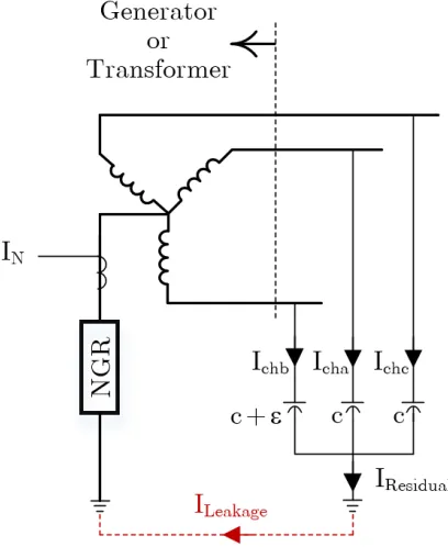
Ground-ing Resistor (NGR). This NGR is obtained by a very small resistor, i.e., less than 1Ω, behind a single phase Neutral Grounding Transformer (NGT) with the turn ratio of 40-100. The resistor suppresses the LG fault current to 3.75-25 A to maintain the op-eration of the power network during the first ground fault. The primary terminals of the NGT are connected to neutral and earthing nodes. The other way to obtain this kind of grounding is to install the small resistor at secondary of grounded-wye-to-broken-delta line PTs, or terminal grounding transformers [31]. It should be noted that the high resistance grounding can be performed without the NGT as well, but it is not an economical alternative [3, 5]. Lastly, the available measurements with this method are the neutral current, and neutral or residual voltage. In general, the resulted NGD with this grounding method is either an NGR, NGR+NGT, or NGR+GT as shown in the following figures for a generator.
Figure 2.1: High resistance grounded generator. a) without NGT, b) with NGT, and c) with terminal grounded-wye-to-broken-delta grounding transformer [3, 5, 31].
Resonant groundingalso known as tuned reactor or ground fault neutralizer means
in the same way as shown in Figure 2.1(b). The inductor is so designed that the seen reactance at primary of the NGT is equal to one-third of the system line-to-ground capacitance. This apparatus suppresses the LG fault current to 5 A to maintain the operation of the power network during the first ground fault. Hence, the resulted NGD is a reactor plus a NGT referred to as NGL+NGT or HNGL. The available measurements by this method are the neutral current and voltage. In fact, the NGT operates as a Potential Transformer.
Hybrid grounding is the combination of solid and high resistance grounding
tech-niques. In this method, the solid grounding serves in the absence of the ground faults. Once the ground fault occurs, and ground current is sensed, the protection system switches from the solid grounding to high-resistance grounding. Through such a strategy, the solid grounding controls the transient overvoltages that appear right after the fault incidence. Moreover, it provides sufficient current for ground fault detection and instan-taneous overcurrent protection. The high resistance grounding which comes to service after a few power frequency cycles suppresses the ground fault current to a few amperes to avoid the mechanical and thermal damages to the equipment. The resulted NGD is actually an NGR which shows zero resistance in unfaulted condition and high resistance in the presence of ground faults [3]. It should be noted that hybrid grounding can be achieved by combining any of the aforementioned grounding techniques, e.g., solid and resonant grounding methods.
2.1.2
Neutral Grounding Devices
On the basis of the introduced neutral grounding methods, following NGDs exist which are explained.
The Neutral Grounding Resistor (NGR) is used in low-resistance,
about 100 since it contains very negligible inductance as well [12].
Figure 2.2: A typical NGR constructed with 6 series edge-wound resistive elements closed with a bar type current transformer [32].
The Neutral Grounding Transformer (NGT) is another apparatus that is used
for neutral grounding. It can be found in high resistance and resonant grounding. Lastly, theNeutral Grounding Inductor (NGL)is used in effective, low-reactance
and resonant neutral grounding methods. Unlike the NGR, it is composed of one single coil reactors. The quality factor of this element (X/R) is about 20.
2.1.3
Failure of Neutral Grounding Devices
NGRs fail due to natural incidents such as lightning, storm, earthquakes, extended service life, corrosive atmosphere, extreme temperature variations, and hail. The other causes are third harmonic currents, manufacturing defects, and vibration [11, 17]. A sample failed NGR due to thermal issues is shown in Figure 2.3.
mechan-Figure 2.3: Thermal failure of NGR [11].
ical assembly. The spot welding defect occurs due to wide range temperature variation and fault current thermal forces. The fillet welding breakage happens due to mechanical stress caused by fault currents, corrosion, and uneven thickness of the welding. Depend-ing on the location of the defection, the NGR can be partially or completely failed-short or failed-open.
Furthermore, another work shows that NGR can be burnt because of overvoltage tran-sients initiated by high-frequency (125 kHz) oscillations involving the inherent inductance of the NGR and system charging capacitances. This phenomenon is known as ferroreso-nance [12]. The waveform of the neutral voltage containing the 125 kHz oscillations, and resulted failed-open NGR are shown in Figures 2.4 and 2.5.
Figure 2.4: Overvoltage due to
Unlike the NGRs, the NGLs do not have lots of mechanical connections and are constructed using a single coil or winding. Hence, failure of these elements is not as popular as the NGRs.
2.2
Importance of Monitoring The Neutral-to-Ground
Path
Properly designed neutral grounding systems eliminate many of the issues and challenges associated with solidly grounded and ungrounded traditional systems while maintaining the same advantages. Any kind of degradation of NGDs causes the risk of ungrounded or solidly grounded neutral and the consequent issues [9]. Depending on the failure mode, i.e. failed-open or failed-short, this can disable ground protection system, cause significant damage to the power system equipments during ground faults, risk the safety of site personnel, etc. As such, most of the utilities perform periodical investigations to detect such a failure. However, planned-maintenances or periodical inspections/tests guarantee the intactness of these apparatuses only during the investigation as the failed-short and failed-open NGRs have been detected right after preventive maintenances [11]. Coal mining industry has widely mentioned this issue regarding the NGRs. This industry experiences change in resistance of NGRs that is a major problem in protection aspect of view. Many events have been reported by this industry that a failed NGR has been identified as the main reason. A few reported events are: 1) a victim at an underground coal mine in Virginia on November 11, 1991, 2) soft starter failure due to an open NGR, and 3) nine loose connections in Eastern Canada on a 200 A, 4160 V NGR [9].
Electrical Code (NEC) 2005 [13], and for all NGR applications per Sections 1-6 and 10-1102.3 of Canadian Electrical Code (CEC) 2018 [14]. As understood from these resources, industries of the North America shall continuously monitor the NGRs to guarantee a safe operation during the likely-to-happen ground faults [15].
2.3
Existing Monitoring Methods – Passive
Cate-gory
Continuity of service, integrity and intactness of the NGRs have been unavoidable con-cerns of many industries for decades worldwide especially in Canada. It can be said that Canada is one of the frontiers in the field of continuous NGR monitoring due to industries that are well-known in competition [19, 20, 21, 28, 29]. The [16, 17] also show the record of this practice in Slovenia. In USA, the continuity of service and connectivity of the grounding path has been focused as can be found in [23, 24, 27]. India has contributed in this industrial field as well [25].
methods is that none of them could provide monitoring in de-energized state of the power system. As mentioned earlier, these techniques do not inject signals and rely on existing electrical parameters of the neutral system. Hence, the monitoring will be disabled if these electrical parameters become absent due to any reason.
2.3.1
Method P1 – Preventive maintenance
The first method, hereafter referred to as preventive maintenance or method P1, has a very long history that goes back to even the first days of appearance of the power systems which is nothing but the periodical or planned inspections, tests, maintenances or investigations. This practice exists even these days where the power systems are highly advanced. The [11] mentions this method with minimum degree of satisfaction since it guarantees the integrity of the assets only during the investigation and not after that. This means the inspected device could fail even right after the test. Moreover, the [11] mentions that a few open NGRs have been detected after completion of a planned maintenance. Thus, this method cannot guarantee continuous monitoring of the NGDs. It is classified under passive methods since it does not inject any signals to the power network. Although this method is not a continuous monitoring alternative; however, it provides a minimum level of monitoring applicable to almost any possible kind of NGDs. A few case studies are presented for preventive-maintenance-based NGR monitoring. As the first record, a conducted inspection of the NGRs in a 60-year-old chemical plant with 80 substations of various ages has resulted detection of two failed-open NGRs among ten high-resistance grounded substations yielding 20% chance for NGR failure [11].
Second, five NGRs have been detected faulty at a P&G’s facilities during an inves-tigation of eight NGRs shortly before they were about to be empowered. These NGRs were unintentionally left disconnected after transformer testing. The issue was solved by manually reconnecting the NGRs. This case means even the inspection itself could cause failed-open NGR situation. How long would these undetected failed-open NGRs have risk the network safety without continuous monitoring [15]?
to the overhang of the building, and an iceberg sized icicle had fallen over the screened enclosure. The enclosure and the resistor were both crushed by the impact. The same question rises here which bolds the importance of continuous monitoring [15].
2.3.2
Method P2 – Neutral Current Supervision
Second technique, hereafter referred to as method P2 or method IN, is classified under passive methods. This technique measures the negligible current of the neutral wire that flows through the NGR as well. This current is induced in neutral system due to inherent asymmetry of the power system components. Figure 2.6 shows a sample resis-tance grounded wye-connected transformer or generator configuration. A very negligible imbalance of the phase-to-ground capacitors of this system causes the residual current. This current which will be referred to as leakage current circulates through the neutral system including the NGR as well.
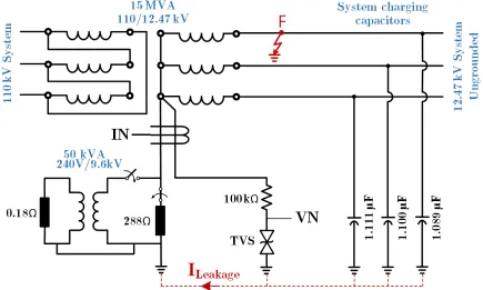
Figure 2.6: Connection diagram of the monitoirng method P2.
following constraint turns the NGR failure detection signal on.
0.01%< IN <120% (2.1)
where the base value is neutral let-through current (Ilet). The failed-open NGR is
de-tected only if the NGR current declines to less than the lower threshold disregarding the operation mode of the power system. This means that the NGR is completely discon-nected. Therefore, if the NGR fails partially open, this method will not be able to detect it. Moreover, the failed-short NGR is detected only if the neutral current rises beyond the maximum expected level which is 120% of the Ilet that is experienced during the LG
fault. Obviously, if the NGR fails partially shorted in the absence of ground faults, its failure will remain undetected until a ground fault occurs. As such, this method has many shortcomings even though it is very economical since the only needed measure-ment instrumeasure-ment is already installed for the protection system. The first issue with this method is that it cannot detect partial failure of the NGR. Second, neutral current is not a reliable or satisfying parameter for the aimed monitoring system. Third, it is mainly an overcurrent ground protection scheme rather than a continuous monitoring technique. Yet, it provides a very limited performance for monitoring the NGR. It should be noted that neutral current supervision can be used for monitoring the other types of NGDs, and even the continuity of service of the solid grounding [9, 11].
2.3.3
Method P3 – Impedance Supervision Using
V
Nand
I
NAs known, the impedance is the best parameter to detect the intactness, integrity, and continuity of service of power system components. This concept appears in following monitoring techniques causing better performance .
Figure 2.7: Connection diagram of the monitoirng method P3.
voltage is so low that the utilized voltage metering instrument (PT) cannot provide an accurate measurement. As such, only the neutral current is used which is applied to neutral current supervision logic. As mentioned for previous method, this logic cannot detect partial failure. As a result, the method VNIN cannot detect partial failure during the normal operation condition. However, the impedance supervision logic, Equation 2.2, that is employed during the faulted condition of the power system detects all kinds of degradation of the NGR.
80%<|ZN|< 120% [9] (2.2)
Figure 2.8: Monitoring algorithm of method P3.
detection is required and necessary before ground faults incidence to guarantee a safe operation during the likely to happen ground faults.
2.3.4
Method P4 – Impedance Supervision Using
V
0and
I
NThe fourth method, hereafter referred to as method P4 or method V0IN, is classified under passive methods category. The measurement points and connection diagram of the configuration are shown in Figure 2.9. The monitoring principles and concepts of this technique are the same as the method VNIN. The only difference is the neutral voltage metering mechanism. This technique uses the residual voltage instead of neutral voltage since the applicable configurations do not have the neutral PT. However, the neutral voltage is obtained by grounded-wye-broken-delta PT configuration that provides the residual voltage at terminals of the generators and transformers, as shown in Figure 2.9 [16, 17].
Figure 2.9: Connection diagram of the monitoirng method P4 [16, 17].
method relies on impedance supervision on a wider range compared to previous method resulting a better performance. The monitoring algorithm is the same as shown in Figure 2.8 except that the voltage threshold is 1% instead of 10%.
Again, it should be noted that although this technique guarantees an acceptable monitoring during the ground faults, however, it is not an widely used practice since NGR failure detection is required and necessary before ground faults incidence to guarantee a safe operation during the ground faults.
2.3.5
Method P5 – Impedance Supervision Using
V
RPDand
I
NFigure 2.10: Connection diagram of the monitoirng method P5 [18].
of NGR voltage measurement from 0.1%, to the phase voltage rating. However, the very weak voltages appearing across neutral system, i.e., less than 0.1% which happen during the normal condition, cannot be measured by this technique unless a high sampling res-olutions is employed. This monitoring method uses the same algorithm as the previous method with some enhancements as shown in Figure 2.11. The enhancements are the switching level between the neutral current and impedance measurement logics. This level indicates the reliability of the method. In fact, the lower this threshold declines the more reliable it becomes since lower levels of this threshold makes the impedance supervi-sion logic more dominant than the current supervisupervi-sion logic. The impedance supervisupervi-sion logic functions very strong, while the neutral current supervision logic functionality is very limited since the neutral current supervision logic only detects the completely dis-connected or failed-open NGR while the impedance supervision logic detects even the partial failure of the apparatus. The ground fault constraint is now changed to following constraint which is the switching criteria between monitoring logics.
VN > 0.1% (2.3)
Figure 2.11: Monitoring algorithm of method P5.
supervision logic functions during the unfaulted conditions that the neutral voltage is very weak and less than the minimum accuracy limit of the used RPD [18].
2.3.6
Method P6 – Impedance Supervision Using
V
T VSand
I
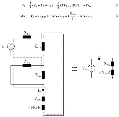
NThe sixth monitoring technique, hereafter referred to as method P6 or method VTVSIN, is classified under passive category. The functionality of this method is inverse of the methods P4 and P5. It uses a sensitive CT, and a new mechanism for neutral voltage metering called sensing resistor, as shown in Figure 2.12. It is mainly composed of a Transient Voltage Suppressing (TVS) diode, and an isolation or protective resistor. It provides very accurate voltage metering in unfaulted systems where the neutral voltage is very weak and in the order of a few volts even in medium voltage distribution systems. The isolation resistor (R1) limits the TVS current to its maximum tolerating
Figure 2.12: Connection diagram of the monitoirng method P6.
voltage, the TVS acts open, and the neutral voltage is accurately measured. However, if neutral voltage becomes noticeable such as during ground faults, the TVS acts shorted bypassing the measurement points to protect the relay against the neutral transient over-voltages. Hence, it can be said that the neutral voltage measurement is not valid when it becomes greater than the clamping level of the TVS diode. As a result, this new mechanism does not provide neutral voltage metering during the ground faults. The I-V characteristic of a sample TVS diode with the breaking voltage equal to 9 V is shown in the following graph.
On the basis of the understood operation modes of the sensing resistor technique, this monitoring method employs the impedance supervision logic during the unfaulted con-dition, and the neutral current supervision logic during the faulted condition. It should be mentioned that the clamping level of the TVS diode is designed greater than the maximum known voltage at neutral in absence of ground faults. As explained earlier, since the impedance measurement logic can detect partial failure of the NGR, this mon-itoring method functions very strong in unfaulted condition. However, since the neutral current supervision logic cannot detect partial failures of the NGR, the performance of this monitoring technique is very limited during the ground faults. Yet, it can detect the failed-short and failed-open NGR conditions in the presence of ground faults. The monitoring algorithm is shown in Figure 2.14 [1, 9, 19, 20, 21, 22].
Figure 2.14: Monitoring algorithm of method P6.
Lastly, it should be noted that although this monitoring technique cannot guarantee a safe operation during the ground fault, however, it is the most popular passive technique since it operates strongly in unfaulted condition. In fact, detecting degraded NGR before incidence of ground faults is more of interest to guarantee protecting the power system equipment in case of an upcoming ground fault. Following, a few case studies that have been solved by this technique are reviewed briefly.
![Fig ur e 2 .1 : Hig h r e s is t a nc e g r o unde d g e ne r a t o r . a ) w it ho ut NG T , b) w it h NG T , a nd c )g r o undingt r a ns f o r me r [3 , 5 , 3 1 ].](https://thumb-us.123doks.com/thumbv2/123dok_us/1927248.1253077/33.612.172.464.419.630/fig-hig-unde-ne-ng-ng-nd-undingt.webp)
![Fig ur e 2 .2 : A t y pic a l NG Rc o ns t r uc t e d w it h 6 s e r ie s e dg e - w o und r e s is t iv e e le me nt s c lo s e dw it h aba r t y pe c ur r e nt t r a ns f o r me r [3 2 ].](https://thumb-us.123doks.com/thumbv2/123dok_us/1927248.1253077/35.612.134.496.104.330/fig-pic-ng-rc-und-aba-pe-ur.webp)
![Fig ur e 2 .3 : T he r ma l f a ilur e o f NG R[1 1 ].](https://thumb-us.123doks.com/thumbv2/123dok_us/1927248.1253077/36.612.345.517.551.681/fig-ur-t-he-ma-ilur-ng-r.webp)