Abstract
LIU, YAXI. A Study on the Feasibility of Electron-based Accelerator Driven Systems
for Nuclear Waste Transmutation. (Under the instruction of professors Man-sung Yim and David McNelis.)
Nuclear waste transmutation is an important option for the development of advanced
fuel cycle and effective nuclear waste management. The electron accelerator driven system
(ADS) was investigated in the study for nuclear waste transmutation as an alternative to proton based ADS. Target design and optimization was carried out to obtain maximum
neutron generation. Subcritical core design based on single and multiple targets was
investigated. System performance between electron-based ADS and proton-based ADS was
compared in terms of neutron generation rate, transmutation efficiency and power generation. It was determined that the electron-based target was capable of providing high neutron flux,
small target geometry size, small scale subcritical core, and low radiation damage. Multiple
target design in the electron-driven ADS was also explored to flatten power distribution in the
ADS subcritical core. Regarding transmutation, the power peaking factors in both the electron- and proton- ADS increase ~ 10% during the burnup period of 700 days. Thermal
power in proton ADS is higher than that of electron ADS by a factor ~ 20. The transmutation
effectiveness of preliminary electron-based ADS is smaller by a factor of 11 compared to
preliminary proton-based ADS. Proton ADS has higher radiation damage to target materials
and surrounding materials. The capital cost for electron-based and proton-based accelerator facility is fairly comparable with the cost of proton-based facilities being slightly higher by a
factor of 20%.
Comparing with the proton-driven ADS, the electron-driven ADS pros include small
target size and small core scale, multiple target possibility for low PPF, low radiation damage to target surroundings, wide availability electron beam at ~100 MeV, and low capital cost of
electron accelerator facility. There are also aspects against electron-driven ADS, including
low efficiency of neutron generation rate, low transmutation efficiency, low thermal power,
A Study on the Feasibility of Electron-based Accelerator Driven Systems
for Nuclear Waste Transmutation
by
Yaxi Liu
A dissertation submitted to the Graduate Faculty of North Carolina State University
in partial fulfillment of the requirements for the Degree of Doctor of Philosophy
Nuclear Engineering
Raleigh, North Carolina May, 2006
Approved by
_____________________________ _____________________________
Dr. Mohamed A. Bourham Dr. John F. Muth
_____________________________ _____________________________
Biography
Yaxi Liu was born in Shaoyang city, Hunan Province, China. He received his Bachelor
of Engineering degree in Engineering Physics in July 1997, from the Department of
Engineering Physics, Tsinghua University, Beijing, China.
He worked as a research engineer in the Daya Bay Nuclear Power Plant (Department
of Operation and Maintenance), Guangdong, China from 1997 to 2000. He served as member
of a cooperative international engineering team between the Daya Bay NPP, China and
Framatome, France.
The author became a PhD student in the Department of Nuclear Engineering at North
Carolina State University in Raleigh, North Carolina, in January 2001. He was mentored by
Professors Man-Sung Yim and David McNelis, in the research of accelerator driven systems
for nuclear waste transmutation. His research work included computational modeling of target
and core design for accelerator-driven subcritical systems, radiation damage to target, and a
performance comparison of electron- and proton-based accelerator driven subcritical reactor
systems.
In the fall of 2001, he reunited with his wife, whose support helped him concentrate on
his studies and the completion of his work for the PhD degree. In December 2004, they had
Acknowledgements
I would express my genuine gratefulness to Professor Man-sung Yim, my advisor and
chair of advisory committee. He took extraordinary efforts in instructing and assisting me
throughout the research of feasibility study of electron-based accelerator driven system for
nuclear waste transmutation. His guidance and encouragement play a principal role for me to
overcome the difficulties in the research work. His insight and creative ideas intrigued my
thoughts during the whole research.
I would like to thank my respectful advisor, Professor David McNelis, for giving me
this great research opportunity to work in the nuclear waste transmutation field, and I
sincerely thank him for all the academic guidance and advices, as well as the non-academic
ones. His continuous and strong support led a smooth way to my study of a PhD degree.
I would also like to express my gratitude to my advisory committee: Professor John F
Muth, Professor Mohamed A. Bourham, for all the precious advices they gave me.
Furthermore, I greatly appreciate the liberal assistance during the research work from
Dr. Donald Dudziak, Dr. Avneet Sood, Dr. Erich Schneider, Los Alamos National Laboratory;
Dr. Denis Beller, Idaho Accelerator Center; and Dr. James Jones, Idaho National Laboratory.
Last but not least, I would like to thank all my fellow colleagues: Dr. Wei Lu, Dr. Jun Li, Mr.
Roger Sit, for the valuable discussions and their friendship. This doctoral program certainly
would not have been possible without the encouragement and support by my parents and my
wife Bingjuan Ye.
This research was financially supported through The Russell Family Foundation
Table of Contents
List of Tables...vi
List of Figures...viii
Chapter 1 Introduction and Overview...1
1.1 Nuclear Waste Issue...1
1.2 Accelerator-driven transmutation of waste...2
1.3 Motivation to Perform this Work...4
1.4 Proposed Work and Tasks...5
Chapter 2 Accelerator-driven Transmutation Waste...8
2.1 Introduction and Background...8
2.1.1 Management and Treatment of Spent Fuel...8
2.1.2 ATW Concept...10
2.1.3 ATW Features...12
2.2 ATW Research & Development in USA...13
2.2.1 Separations Technology and Transmutation Systems...14
2.2.2 A Roadmap for Developing ATW Technology, Sept 1999...16
2.3 Proton-based ATW Conceptual Design...19
2.3.1 Proton Accelerator Beam...19
2.3.2 Proton-Based ADS Concept...20
2.4 Electron ADS Preliminary Design...23
2.4.1 Bremsstrahlung Physics...23
2.4.2 Electron-Based ADS Concept...25
Chapter 3 Study on Target Design for Accelerator Driven System...28
3.1. Background of Bremsstrahlung and Photonuclear interaction...28
3.2. Methods and Approaches - Surface Matrix Arithmetic...31
3.2.1: Basic Matrix Arithmetic with Target Cylindrical variables...31
3.2.2: MCNPX Variance Reduction in Electron ADS...33
3.3. Simulation Results and Analysis for Electron-based Target...34
3.3.1: Target Materials Selection...34
3.3.2: Electron Beam Energy Selection...37
3.3.3: Target Geometry Optimization...40
3.4. Methods and Approaches - Mesh Tally Method...47
3.4.1: MCNPX New and Advance Tally Feature, Mesh Tally...47
3.4.2: Electron, Bremsstrahlung Photon and Photoneutron Distribution in Thick Target...49
3.5: Impact of Various Electron Beam Size on the Neutron Flux Angular Distribution in Thick Target 62 3.5.1: Neutron Flux Distribution with Electron Accelerator Beam Size ranging from 1cm to 10cm in Radius...62
3.5.2: Selected Beam Size and Associated Target Geometry...68
3.6 Study of Proton-based Target...72
3.6.2 Proton Accelerator Target Neutron Flux Distribution and Beam Size Impact by Mesh Tally 75
3.7 Comparison of Electron-driven Target and Proton-Driven Target...82
3.7.1 Neutronic Behavior of Electron-driven Target and Proton-Driven Target...84
Chapter 4 Radiation Damage Production Calculations...90
4.1. Introduction of Radiation Damage Production to Target...90
4.1.1: Radiation production of displacement of atom...91
4.1.2: Radiation Production Modeling and Simulation...92
4.2. Radiation Damage Production to Target Materials in Electron-based ADS...93
4.3. Radiation Damage Production to Target Materials in Proton-based ADS...96
Chapter 5 Electron Accelerator Driven Subcritical Core Design...99
5.1 Overall Preliminary Subcritical Core Design...99
5.1.1 Analysis on the reactivity during burnup of ADS...100
5.1.2: The Keff Selection Approach in Electron-driven Core Design...102
5.2 Options for a Subcritical Core in an Electron Accelerator-Driven System...103
5.2.1: Single Target Core Design...104
5.2.2: The Simulation of Subcritical Core in Electron-driven System...105
5.3 Multi target Preliminary Core Design...107
5.3.1 Neutron flux inside the core...108
5.3.2 The power distribution and power production in Electron ADS... 111
5.4 Transmutation Effectiveness Evaluation... 114
5.4.1: Transmutation Efficiency Evaluation Methods Description... 117
5.5 Burnup and System Parameters in Preliminary Conceptual Electron ADS... 118
5.5.1: Single Target Electron-ADS Burnup and System Parameters... 119
5.5.2: Single Target Electron-ADS Burnup and System Parameters by using MOX Fuel.124 5.5.3: Three-target Electron-ADS Burnup and System Parameters with fuel loading I...129
5.5.4: Three-target electron-ADS burnup and system parameters with fuel loading II...133
5.6 Burnup and System Parameters in Pre-conceptual Proton ADS...139
5.6.1: Proton-ADS burnup and system parameters with fuel loading I...139
5.6.2: Proton-ADS Burnup and System Parameters Fuel Loading Case II...144
Chapter 6 Capital Cost Study of Electron Accelerators and Proton Accelerators...152
6.1 Capital Cost Estimation of Electron Accelerator Beam Facility...152
6.2 Capital Cost Estimation of Proton Accelerator Beam Facility...155
Chapter 7 Summary and Conclusions...163
7.1 Key observations and conclusions...165
7.2 Proposed future works...167
List of Tables
Table 1: Long-Lived Nuclear Waste Constituent, Relative Quantities by Mass of Long-lived
Isotopes Occurring in Spent Reactor Fuel...10
Table 2: JAREI Proposed Concept Proton ADS System Performance Parameters [OECD, 1994]...22
Table 3: Simulation Computation Time without/with Energy Cutoff...33
Table 4: Approximate Neutron Yields from Thick Targets and converted to Neutron Ratio...34
Table 5: Neutron yield comparison between for various target materials with 100Mev Electrons...35
Table 6: Neutron generation per electron as function of accelerator energy and target materials...36
Table 7: Electron Linear Accelerator Laboratories Facility Details...38
Table 8: Comparison Ratio of neutron to electron with facilities data and simulation results..39
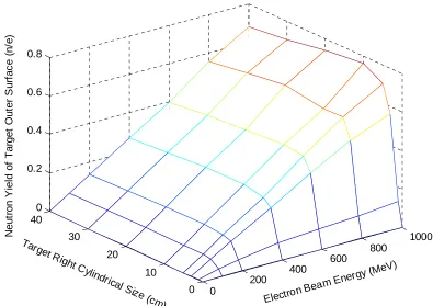
Table 9: Neutron Yield per electron escaping from Target Outer Surface as Function of Electron Beam Energy and Target Size...39
Table 10: Bottom Surface Neutron Yield with variables of Target Diameter and Thickness....41
Table 11: Side Surface Neutron Yield with variables of Target Diameter and Thickness...43
Table 12: Top Surface Neutron Yield with variables of Target Diameter and Thickness...44
Table 13: Total Outer Surface Neutron Yield with variables of Target Diameter and Thickness ...46
Table 14: Electron, photon and neutron peak flux in various targets driven by 100 MeV and 1GeV electron...61
Table 15: Neutron Generation from top, bottom and side surfaces driven by 1GeV electron with beam size as variable, Target size: Radius * Height as 5cm *7cm...68
Table 16: Neutron Generation from top, bottom and side surfaces driven by 1GeV electron with beam size as variable, Target size: Radius * Height as 5cm *7cm...70
Table 17 Neutron Production Escaping from Proton-based Target with 1 GeV Proton Beam73 Table 18: Neutron generation per proton as function of accelerator energy and target materials...75
Table 19: Neutron Generation from top, bottom and side surfaces driven by 1GeV proton with beam size as variable, Target size: Radius * Height as 10cm *40cm...79
Table 20: Neutron Generation from top, bottom and side surfaces driven by 1GeV proton with beam size as variable, Target size: Radius * Height as 20cm *30cm...82
Table 21: Technical Parameters of Proton-based and Electron-based ADS Target...83
Table 22: Threshold Radiation Energy for Displacement [Kinchin, 1955]...91
Table 23: Bucklings and fluxes or critical bare reactors...106
Table 24: Alloy Fuel Core System, Proposed by Japan Atomic Energy Research Institute (JAERI)... 115
Table 26: MOX Fuel Core System, Proposed by Brookhaven National Laboratory (BNL, USA)
... 116
Table 27: Particle Fuel Core System, Proposed by BNL (Brookhaven National Laboratory, USA)... 116
Table 28 : Isotopic mass balance (gram) in Electron-ADS with fuel loading I...120
Table 29: Isotopic mass balance (gram) in single-target Electron-ADS with fuel loading II (Identify II)...125
Table 30: Isotopic mass balance (gram) in three-target Electron-ADS with fuel loading I...130
Table 31: Isotopic mass balance (gram) in Three-target Electron-ADS with fuel loading II..135
Table 32: Isotopic mass balance (gram) in Proton-ADS with fuel loading I...140
Table 33: Isotopic mass balance (gram) in Proton-ADS with fuel loading II...145
Table 34: Overall Electron-ADS and Proton-ADS burnup and system parameters...150
Table 35: Worldwide Existing and Proposed Proton Sources...156
Table 36: SNS Super-Conducting Linac Architecture Parameters...157
Table 37: Cost Summary of the SC Linac from 194 MeV to 1000 MeV...158
Table 38: An 8GeV proton booster machine parameter...159
Table 39: SNS Super-Conducting Linac Architecture Parameters [SNS-SRF, 1999]...160
Table 40: Capital Cost of a Proton Driven Machine Basic Structure...161
List of Figures
Figure 1: Constituents of Spent Nuclear Fuel [INEEL, 2003]...8
Figure 2: Chart of Important Actinides and Minor Actinides Associated with Nuclear Waste [Office of Nuclear Energy, Science, and Technology, 2003]...9
Figure 3: Typical Reaction Types Layout of Nuclear Waste Transmutation... 11
Figure 4: Spent Fuel Accumulation as Function of Time...14
Figure 5: Layout of Main Component, Preliminary ADTT System...15
Figure 6: Layout of Preliminary ADTT System [Office of Nuclear Energy]...18
Figure 7: Proton ADS Layout, Adapted from Schematic Figure of Accelerator- Driven Transmutation Concept -Alloy Fuel Core System [OECD, 1994]...21
Figure 8: Electromagnetic Cascade...23
Figure 9: Layout of High-Energy Electron Induced Neutron Fission by PNNL...26
Figure 10: Cylindrical Geometry Target with Electron Beam Driven on the Cylindrical Axes..29
Figure 11: Angular dependence of the thick-target bremsstrahlung intensity integrated over photon energy from 1.25 to 2.35 MeV [Buechner, Van De Graaff, 1948]...30
Figure 12: Target Disc Piled up and multiple planar surfaces...32
Figure 13: neutron generation as function of electron accelerator energy and target materials ...36
Figure 14: Neutron Yield as Function of Electron Beam Energy and Target Size...40
Figure 15: Bottom Surface Neutron Yield as Function of Target Diameter and Thickness with Uranium Target Driven by 1Gev Electron Beam...42
Figure 16: Side Surface Neutron Yield as Function of Target Diameter and Thickness with Uranium Target Driven by 1Gev Electron Beam...43
Figure 17: Top Surface Neutron Yield as Function of Target Diameter and Thickness with Uranium Target Driven by 1Gev Electron Beam...45
Figure 18: Total Outer Surface Neutron Yield as Function of Target Diameter and Thickness with Uranium Target Driven by 1Gev Electron Beam...46
Figure 19: Electron Flux Axial Distribution at X=0 Slide, in Uranium Thick Target Driven by 1 GeV Electron Beam, with beam size R=1cm...50
Figure 20: Electron Flux Radial Distribution in Uranium Thick Target Driven by 1 GeV Electron Beam at Z= - 3.8cm plane, with beam size as 1cm in radius...51
Figure 21: Photon Flux Axial Distribution in Uranium Thick Target Driven by 1 GeV Electron Beam at X=0 plane...52
Figure 22: Photon Flux Radial Distribution in Uranium Thick Target Driven by 1 GeV Electron Beam at Z= - 3.6cm plane, with electron beam size as 1cm in radius...53
Figure 23: Neutron flux axial distribution in electron-based target (Uranium) driven by 1GeV electron beam, beam size radius =1cm...54
...55 Figure 26: Electron, photon and neutron flux distribution in electron-based target (Bismuth)
driven by 100MeV electron beam...56 Figure 27: Electron, photon and neutron flux distribution in electron-based target (Bismuth)
driven by 1GeV electron beam...56 Figure 28: Electron, photon and neutron flux distribution in electron-based target (Lead)
driven by 100MeV electron beam...57 Figure 29: Electron, photon and neutron flux distribution in electron-based target (Lead)
driven by 1GeV electron beam...57 Figure 30: Electron, photon and neutron flux distribution in electron-based target (Tantalum)
driven by 100MeV electron beam...58 Figure 31: Electron, photon and neutron flux distribution in electron-based target (Tantalum)
driven by 1GeV electron beam...58 Figure 32: Electron, photon and neutron flux distribution in electron-based target (Tungsten)
driven by 100MeV electron beam...59 Figure 33: Electron, photon and neutron flux distribution in electron-based target (Tungsten)
driven by 1GeV electron beam...59 Figure 34: Electron, photon and neutron flux distribution in electron-based target (Uranium)
driven by 100MeV electron beam...60 Figure 35: Electron, photon and neutron flux distribution in electron-based target (Uranium)
driven by 1GeV electron beam...60 Figure 36: Electron, photon and neutron flux peak in electron-based target driven by 100MeV
and 1GeV electron beam separately with beam size radius as 1cm...61 Figure 37: Schematic of E-beam driven target...63 Figure 38: Neutron flux axial distribution in YZ slice at X=0 in target with beam size Radius as
2cm, Target size: Radius * Height as 5cm *10cm...64 Figure 39: Neutron flux axial distribution in YZ slice at X=0 in target with beam size Radius as
3cm, Target size: Radius * Height as 5cm *10cm...65 Figure 40: Neutron flux axial distribution in YZ slice at X=0 in target with beam size Radius as
4cm, Target size: Radius * Height as 5cm *10cm...66 Figure 41: Neutron flux axial distribution in YZ slice at X=0 in target with beam size Radius as
5cm, Target size: Radius * Height as 5cm *10cm...67 Figure 42: Neutron flux axial distribution in YZ slice at X=0 in target with beam size Radius69 Figure 43: Neutron flux axial distribution in YZ slice at X=0 in target with beam size Radius as
2.5cm, Target size: Radius * Height as 5cm *7cm...69 Figure 44: Neutron flux axial distribution in YZ slice at X=0 in target with beam size Radius as
3cm, Target size: Radius * Height as 5cm *7cm...70 Figure 45: Neutron Production Escaping from Proton-based Target as Function of Target
Figure 47: Proton and Neutron flux axial distribution in YZ slice at X=0 in Proton-based target
with beam size Radius as 1 cm, Target size: Radius * Height as 10cm * 40cm...76
Figure 48: Proton and neutron flux axial distribution in YZ slice at X=0 in Proton-based target with beam size radius as 2 cm, Target size: Radius * Height as 10cm * 40cm...77
Figure 49: Neutron flux axial distribution in YZ slice at X=0 in Proton-based target with beam size Radius = 3 cm, Target size: Radius * Height as 10cm * 40cm...78
Figure 50: Neutron flux axial distribution in YZ slice at X=0 in Proton-based target with beam size Radius = 4 cm, Target size: Radius * Height as 10cm * 40cm...78
Figure 51: Neutron flux axial distribution in YZ slice at X=0 in Proton-based target with beam size Radius = 5 cm, Target size: Radius * Height as 10cm * 40cm...79
Figure 52: Neutron flux axial distribution in YZ slice at X=0 in Proton-based target with beam size Radius = 5 cm, Target size: Radius * Height as 20cm * 30cm...80
Figure 53: Neutron flux axial distribution in YZ slice at X=0 in Proton-based target with beam size Radius = 6 cm, Target size: Radius * Height as 20cm * 30cm...80
Figure 54: Neutron flux axial distribution in YZ slice at X=0 in Proton-based target with beam size Radius = 7 cm, Target size: Radius * Height as 20cm * 30cm...81
Figure 55: Neutron flux axial distribution in YZ slice at X=0 in Proton-based target with beam size Radius = 8 cm, Target size: Radius * Height as 20cm * 30cm...81
Figure 56: Electron-driven Target (Uranium) Electron, Photon and Neutron Spectrum, driven by 1GeV Electron beam...86
Figure 57: Proton-driven Target (Uranium) Proton an Neutron Spectrum, driven by 1GeV Proton beam...87
Figure 58: Neutron Spectrum in Uranium Target driven by 1GeV Electron and Proton beam separately...88
Figure 59: Flow chart of calculating the radiation damage production...93
Figure 60: Electron, photon and photoneutron flux distribution in uranium target driven by 1GeV electron beam...94
Figure 61: Electron, photon and photoneutron spectrum in uranium target driven by 1GeV electron beam...95
Figure 62: Proton and neutron flux distribution in uranium target driven by 1GeV proton beam ...96
Figure 63: Proton and spallation-neutron spectrum Uranium target driven by 1GeV proton beam...97
Figure 64: Heterogeneous core layout for electron-based ADS...100
Figure 65: (a) Electron-based ADS Core Z-slice View (Z=0), (b) Electron-based ADS Core X-slice view (X=0) 105 Figure 66: Keff in the EADS preliminary heterogeneous core...107
Figure 67: Preliminary Electron-based ADS core layout with multiple targets...108
Figure 68: Neutron flux in X-Y plane in 3-D display...109
Figure 69: Neutron flux in X-Y plane in 2-D with neutron flux intensity in color maps... 110
Figure 71: Power production using a 1 GeV, 1 mA electron beam as a function of the
subcriticality (1-Keff) in an electron-driven ADSR... 113
Figure 72: Electron ADS Single- target Neutron Spectra inside Core with Fuel Loading I....121
Figure 73: Electron ADS Single-target Total Burnup Mass Balance with Fuel Loading I...121
Figure 74: Electron ADS Single-target Np237 Burnup Mass Balance with Fuel Loading I...122
Figure 75: Electron ADS Single-target Am241 Burnup Mass Balance with Fuel Loading I...122
Figure 76: Electron ADS Single-target Am243 Burnup Mass Balance with Fuel Loading I...123
Figure 77: Electron ADS Single-target Pu239 Burnup Mass Balance with Fuel Loading I...123
Figure 78: Electron ADS Single-target Neutron Spectra inside Core with Fuel Loading II....126
Figure 79: Electron ADS Single-target Total Burnup Mass Balance with Fuel Loading II...127
Figure 80: Electron ADS Single-target Np237 Burnup Mass Balance with Fuel Loading II..127
Figure 81: Electron ADS Single-target Am241 Burnup Mass Balance with Fuel Loading II.128 Figure 82: Electron ADS Single-target Am243 Burnup Mass Balance with Fuel Loading II.128 Figure 83: Electron ADS Single-target Pu239 Burnup Mass Balance with Fuel Loading II..129
Figure 84: Electron ADS Three-target Neutron Spectra inside Core with Fuel Loading I...131
Figure 85: Electron ADS Three-target Total Burnup Mass Balance with Fuel Loading I...131
Figure 86: Electron ADS Three-target Np237 Burnup Mass Balance with Fuel Loading I....132
Figure 87: Electron ADS Three-target Am241 Burnup Mass Balance with Fuel Loading I...132
Figure 88: Electron ADS Three-target Am243 Burnup Mass Balance with Fuel Loading I...133
Figure 89: Electron ADS Three-target Pu239 Burnup Mass Balance with Fuel Loading I....133
Figure 90: Electron ADS Three-target Neutron Spectra inside Core with Fuel Loading II...136
Figure 91: Electron ADS Three-target Total Burnup Mass Balance with Fuel Loading II...136
Figure 92: Electron ADS Three-target Np237 Burnup Mass Balance with Fuel Loading II...137
Figure 93: Electron ADS Three-target Am241 Burnup Mass Balance with Fuel Loading II..137
Figure 94: Electron ADS Three-target Am243 Burnup Mass Balance with Fuel Loading II..138
Figure 95: Electron ADS Three-target Pu239 Burnup Mass Balance with Fuel Loading II...138
Figure 96: Proton ADS Single-target Neutron Spectra with Fuel Loading I...141
Figure 97: Proton ADS Single-target Total Burnup Mass Balance with Fuel Loading I...141
Figure 98: Proton ADS Single-target Np237 Burnup Mass Balance with Fuel Loading I...142
Figure 99: Proton ADS Single-target Am241 Burnup Mass Balance with Fuel Loading I...142
Figure 100: Proton ADS Single-target Am243 Burnup Mass Balance with Fuel Loading I...143
Figure 101: Proton ADS Single-target Pu239 Burnup Mass Balance with Fuel Loading I....143
Figure 102: Proton ADS Single-target Neutron Spectra inside Core with Fuel Load II...146
Figure 103: Proton ADS Single-target Total Burnup Mass Balance with Fuel Loading II...146
Figure 104: Proton ADS Single-target Np237 Burnup Mass Balance with Fuel Loading II...147
Figure 105: Proton ADS Single-target Am241 Burnup Mass Balance with Fuel Loading II..147
Figure 106: Proton ADS Single-target Am243 Burnup Mass Balance with Fuel Loading II..148
Figure 107: Proton ADS Single-target Pu239 Burnup Mass Balance with Fuel Loading II...148
Figure 108: Layout of Electron Accelerator Facility Design with Rhodotron and Booster Synchrotron...153
Chapter 1 Introduction and Overview
1.1 Nuclear Waste Issue
Disposal of nuclear waste is critical to the continuous development and future use of nuclear energy. Nuclear waste results from various activities involving the use of radioactive materials, such as electricity production from civilian nuclear power plants, defense activities and nuclear weapons manufacture, medical treatment, nuclear research, industrial processes.
Nuclear waste can be generally classified as either "low level" radioactive waste or "high level" radioactive waste. Low level nuclear waste usually includes materials used to handle the highly radioactive parts of nuclear reactors and waste from medical procedures involving radioactive treatments or x-rays. Low level waste is comparatively easy to dispose of. The level of radioactivity and the half life of the radioactive isotopes in low level waste are relatively small. Storing the waste for a period of 10 to 50 years will allow most of the radioactive isotopes in low level waste to decay, at which point the waste can be disposed of as normal refuse.
High level radioactive waste is generally materials from the core of the nuclear reactor or nuclear weapon. This waste includes uranium, plutonium, and other highly radioactive elements made during nuclear fission. Most of the radioactive isotopes in high level waste emit large amounts of radiation and have extremely long half-lives (some longer than million years) requiring very long periods before the waste will settle to safe levels of radiation. This area will describe some of the methods being under consideration, for dealing with this high level waste. Nuclear waste has certain well-known features that place it in a special category. It lingers, exhibiting its radioactivity for long periods of time - timescales of tens or hundreds of thousands of years.
and rural areas. Most are located near large bodies of water. The concern is how to ensure isolation of waste to a degree sufficient to prevent severe contamination of resources, especially water resources. The disposal of radioactive waste from nuclear power plants and other high level nuclear waste sources is as politically intense an issue as scientifically.
The concern associated with repository sites and the extremely long periods of isolation required support the view of transmuting long-lived radionuclides into short-lived ones as a potential solution. Transmutation is the transformation of one element into another. The goal of transmutation, in radioactive waste disposal, is to transmute long lived, highly radioactive elements, into shorter lived, less-radioactive elements. Transmutation could be available for deployment in a short time, thus making a positive contribution to the solution of nuclear waste treatment in a timely manner.
1.2 Accelerator-driven transmutation of waste
Nuclear waste transmutation typically requires neutrons to induce nuclear reactions. The neutrons can be provided by either critical nuclear reactors or accelerators. Several countries have considered using accelerator driven transmutation systems for treating spent fuel. These systems are generally referred to as accelerator-driven systems (ADS) or accelerator-driven transmutation technologies (ADTT). The current concept of U.S. ADTT [DOE Roadmap to congress, 1999] is based on the use of powerful continuous proton accelerator. The proton beam generated from the proton accelerator hits the heavy metal target and produces neutrons. The produced neutrons interact with the fuel (causing fission or neutron capture reactions) in the assembly and produce more neutrons, which could also be used in the transmutation process. The waste remaining from these processes would ultimately be incorporated into forms acceptable for disposal. The excess thermal energy from the transmuter would be used to generate electrical power.
consisting of a target/blanket in which spallation reactions convert the proton beam into an intense neutron flux, which could also be used to interact with the plutonium and minor actinides. The generated neutrons from the fission process would be used in the transmutation of long-lived fission products.
ADTT has the potential to generate significantly larger fluxes of neutrons than currently possible with critical reactor sources or pure spallation sources. However, ADS would require extensive development before even technical feasibility could be realistically assessed while applying thermal and fast reactors for transmutation would be based on considerable technological experience.
1.3 Motivation to Perform this Work
Battelle Division of Pacific Northwest Laboratory had earlier investigated the feasibility of nuclear waste transmutation based on electron accelerators [Schneider, 1974]. In a system with electron accelerators, there is a heavy metal converter target to convert the electrons to gamma rays and then gamma rays to neutrons. In other words
both interactions, (e, γ) and (γ, n) would occur inside the converter target. The generated photo neutrons then would be used to transmute transuranics atoms. In that report, the feasibility criteria for the studied system were the reaction yield, which was the number of reactions per incident electron, and the energy supplied per reaction. The investigated electron source was a 34 MeV electron accelerator. For all investigated targets [uranium, lead, tantalum, copper, aluminum, and carbon], small photon yields and hence small photoneutron yields had been observed. The energy required for the transmutation reaction was found to be roughly two orders of magnitude larger than that gained in the most optimistic target case. Thus the energy balance criterion was not met and this scheme was concluded to be not practical. According to their analyses, the energy required to run the system was much more than the energy produced from the facility itself. There were several issues that were not addressed in the PNNL study which demand further investigations. These issues are:
- The potential benefit of using high-energy continuous-wave electron accelerator instead of 34 MeV electron accelerators [i.e. a more advanced accelerator than the one cited in the PNNL report].
- Effects of a target blanket assembly that includes the heavy metal target and the transmuted nuclear waste for the neutron balance.
- Effects of Photo fission reactions for the neutron and energy balance.
With the availability of high energy of electron beam, when coupled with appropriate target materials, high energy electron accelerators can be used to produce large number of neutrons, thus providing an alternative source of neutrons.
(CEBAF) at the Thomas Jefferson National Accelerator Facility (JLab) with electron beam energy of up to 4GeV [Kees de Jager, 2004].
Meanwhile, with the improvement in computational software capability and supporting hardware environment, opportunities to simulate very complex interactions associated with high energy electron particles had become available. The software, MCNPX [Waters, 2002], which based on Monte Carlo method, provides approximate solutions by performing statistical sampling experiments on a computer. Regarding the computational hardware environment, the North Carolina State University High Performance and Grid Computing (HPC) initiative offers high-performance research computing facilities. The high-performance computing makes it efficient to perform extremely time-consuming physical simulation.
Furthermore, more photonuclear cross section data has been available and evaluated through the participation and cooperation of international laboratories, including Los Alamos National Laboratory (LANL), Korea Atomic Energy Research Institute (KAERI), China Nuclear Data Center (CNDC), Institute of Physics and Power Engineering, Russia (BOFOD), Center for Photonuclear Experiments Data (Centr Dannykh Fotoyadernykh Eksperimentov) Russia (CDFE), Japanese Evaluated Nuclear Data Library (JENDL) and Japan Atomic Energy Research Institute (JAERI)
1.4 Proposed Work and Tasks
The objective of this study is to examine the feasibility of electron accelerator-based nuclear waste transmutation in comparison to the proton accelerator accelerator-based approach. An optimized preliminary design of the system was investigated based on simulation and sensitivity analyses by using MCNPX [Waters, 2002]. A comparison on major system performance parameters for both proton-based and electron accelerator-based systems was performed.
The principal design choice to be made between the electron- and proton- driven ADS is the design of subcritical core, including the target. The target is designed to generate the maximum number of neutrons. A study on target material and geometry to maximize neutron generation rate is to be carried out first. A choice between fast- and thermal-neutron spectrum system is to be made. An electron-based subcritical core is to be investigated in terms of reactivity balance, power generation, transmutation efficiency particle distribution, material radiation damage and other safety concerns. Since accelerator driven system is assumed, capital cost estimation is to be investigated in terms of spallation neutrons and photonuclear neutron generating cost.
To accomplish the research objective, the following tasks are proposed.
1. Develop an efficient methodology for tracking neutron generation escaped from target surface
2. Select heavy metal target materials according to their neutron production performance and neutron spectrum
3. Investigate the impact of electron accelerator beam energy on the target neutron production, and the impact of electron accelerator beam size on the neutron flux angular distribution
4. Develop the surface matrix arithmetic method for the optimization of target geometry combined with source particle energy and target materials
5. Perform the neutronic study of the electron-based and proton-based target systems for the purpose of accelerator driven subcritical core design
6. Develop an electron-based accelerator driven subcritical core based on existing proposed proton-based ADS model
7. Layout the flowchart of electron-based core design with the analysis of major components and design alternatives
8. Perform the study of burnup and transmutation calculation for Pu and minor actinides in the proposed electron-based core using single or multiple target design 9. Perform the system performance and analysis in term of thermal power, power distribution, and transmutation efficiency between the electron-based ADS and proton-based ADS
Chapter 2 Accelerator-driven Transmutation Waste
2.1 Introduction and Background
2.1.1 Management and Treatment of Spent Fuel
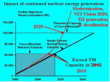
Spent nuclear fuel, the used fuel periodically removed from nuclear power reactors, is one of the most hazardous materials made by man. Nuclear power companies currently store 47,000 tons of spent fuel at 72 sites in 33 states [United States General Accounting Office, 2003]. That amount will increase through 2010, when the Department of Energy (DOE) expects to open a permanent repository for this fuel at Yucca Mountain, Nevada. Management of spent nuclear fuel, specifically the reduction of mass and volume of high-level nuclear waste, requires the use of treatment technologies that separate the constituents of spent nuclear fuel as shown in Figure 1into:
1: uranium (which is approximately 95.6 percent of the spent fuel);
2: short-lived radioactive elements (which decay to harmless species over few hundred years); and
3: long-lived radioactive materials such as plutonium, americium, and other actinides.
Figure 1: Constituents of Spent Nuclear Fuel [INEEL, 2003]
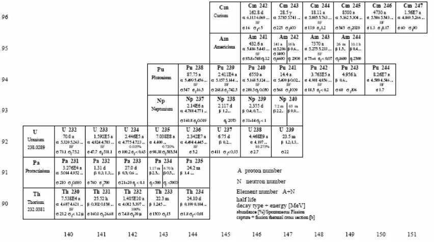
resemble the rare earth (or lanthanide) series. Uranium (U), plutonium (Pu), neptunium (Np), americium (Am), and curium (Cm) are the actinides of importance in determining the long term toxicity and heat load of spent nuclear fuel. Actinides with atomic numbers higher than uranium are called transuranics, and include Np, Pu, Am and Cm. Np, Am, and Cm are known as minor actinides because of their relatively low percentages in the isotopic mix in spent fuel as Figure 2.
Figure 2: Chart of Important Actinides and Minor Actinides Associated with Nuclear
Waste [Office of Nuclear Energy, Science, and Technology, 2003]
The objective of treatment of spent fuel is to
1) Reduce Spent Fuel Volume by creating a final high-level waste form that is lower in volume than the original spent fuel,
2) Separate Long-Lived, Highly Toxic Elements (i.e., actinides such as plutonium and americium) that present the most difficult disposition challenge, and
3) Reclaim Spent Fuel’s Valuable Energy by providing a method to reclaim the energy value contained in the highly toxic spent fuel elements while providing for their destruction.
URanium EXtraction (PUREX) [NCSET, 2002], developed by the United States in the late 1940s, is in active use on a large scale in France, Russia, and the United Kingdom. In the PUREX process, spent fuel is dissolved in acid and fed through a solvent extraction process. The process separates both uranium and plutonium. Afterward, both short and long-lived radioactive materials (neptunium, americium, etc.) are directed to a liquid waste stream, mixed with borosilicate glass, and poured into canisters where it vitrifies. This configuration is highly suitable for long-term storage or disposal. Although PUREX can be used to reduce spent fuel volume by removing the uranium, it has two major drawbacks: it produces separated plutonium (a proliferation concern) and it generates a relatively large amount of high-level waste, which is long-lived nuclides as Table 1.
Table 1: Long-Lived Nuclear Waste Constituent, Relative Quantities by Mass of Long-lived Isotopes Occurring in Spent Reactor Fuel.
2.1.2 ATW Concept
United State of America, European countries, Russia and Japan. ATW begins with a spent fuel treatment center, where the uranium and short-lived fission products that do not need to be transmuted are separated from the rest of the waste. These short-lived fission products are prepared for disposal, while the uranium can be recycled for reuse or prepared for disposal. The remaining transuranics (plutonium, neptunium, americium and curium) are transferred to the waste burner, where they are transmuted into materials that pose mostly short-lived hazards.
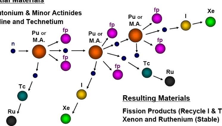
Two types of reaction in nuclear waste transmutation are of importance: neutron-induced fission and neutron capture reaction. In neutron-neutron-induced fission, transuranics are induced by neutron, and then transferred into two nuclei, releasing energy in the form of neutrons, neutrinos, photons, and kinetic movement. The other reaction type is neutron capture, for examples, a radioactive I-129 atom capturing a neutron and being changed
into a stable Xe-130 atom, as shown in Figure 3.
Figure 3: Typical Reaction Types Layout of Nuclear Waste Transmutation
releases energy as it is destroyed by fission in the waste burner, the produced energy could be used to the process of power. Only a fraction of the energy is needed to supply the ATW system; the rest of energy is considered to produce electricity, reducing ATW development and construction costs.
2.1.3 ATW Features
The major attributions of the ATW concept are: (1) it addresses issues of waste management storage capacity by efficiently destroying transuranics (TRU), transmuting long-lived fission products to more benign or stable isotopes, and partitioning of all fission products for optimal disposition, (2) it is reactor-like in scale and function and has the potential to be economically viable by producing usable energy by destroying hazardous components of spent nuclear fuel, (3) ATW allows deep burnup of Pu and minor actinides, while reactors have difficulty in performing multi cycles due to reactivity requirements, and (4) the radio toxicity of the residual material from a transmutation facility after 300 years is lower than direct-disposal of spent nuclear fuel after 100,000 years, thus impacting the local population’s concern over long-term repository performance.
2.2 ATW Research & Development in USA
Figure 4: Spent Fuel Accumulation as Function of Time
ATW potentially can reduce the amount of waste requiring permanent storage to less than 3,000 tons, including less than 1 ton of plutonium. In addition, these wastes would require a few centuries of isolation instead of 10,000 years.
2.2.1 Separations Technology and Transmutation Systems
In June 1991, a 19-member interdisciplinary Separations Technology and Transmutation Systems [STATS, 1991] committee of the U.S. National Research Council was formed at the request of the U.S. Secretary of Energy to evaluate the state of the art of separations and transmutation concepts [Anthony 1996]. The committee’s peer-reviewed findings and recommendations were not encouraging. In essence, the committee felt that any transmutation process would not eliminate the need for a high-level radioactive waste repository and would be less economically attractive than the current once-through fuel cycle. STATS discusses the committee’s concerns and their recommendation that any research undertaken by the U.S. should be modest.
liquid metal fission reactors they evaluated. The ADTT project reviewed by the STATS committee had the aim of reducing TRU waste to such an extent that all waste containing residual TRU would be suitable for shallow land burial. The concepts they reviewed used a thermal neutron spectrum, fluid fuels or molten salt with dissolved radionuclides, and only aqueous separations technology. The current design has evolved significantly with particular attention to the STATS (1996) concerns and recommendations. For example, the committee felt that long-lived fission products may represent an equally significant concern as that of TRU and that advances in reprocessing may allow highly efficient separation operations. Technical improvements to the ADTT conceptual design discussed in this paper include a fast neutron spectrum that allows destruction of long-lived fission products, liquid lead-bismuth eutectic (LBE) coolant and spallation target, solid fuel processing.
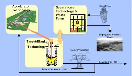
The current U.S. ADTT concept has evolved to the point that it is now based on maturing engineered designs as opposed to its 1991 predecessor. As currently envisioned,
the facility would consist of three major components as illustrated in Figure 5: a
high-power proton accelerator, a spent fuel partitioning and treatment system, and a subcritical reactor containing the target and blanket system.
There is optimism among eight national laboratories and many at research universities that the interfacing of the ADTT’s complex engineered components is achievable. Excerpts from the 1998 MIT review [Schriber, 1998] are summarized as follows:
z No insurmountable issues or show stoppers were identified. While the proposed technologies are in several instances extrapolations of existing experience to untested conditions, they represent reasonable targets for development over the next 5 to 10 years.
z While we do not judge the merits of the [ADTT project] as an option to improve the management of nuclear wastes, we acknowledge that it has the potential to provide added flexibility to the design of the high level waste repository and to reduce the uncertainties about its performance.
z The main technologies to be developed are all worthwhile technologies for other applications beside the transmutation of wastes. We see the spin-offs from the development efforts as equally important reasons for the undertaking of the proposed development program in the next few years.
z There are several commendable attributes, but also questions and caveats to be addressed. The R&D [Research and Development] program is well designed to address these concerns. The U.S. Congress did not provide the necessary funding
2.2.2 A Roadmap for Developing ATW Technology, Sept 1999
Under the U.S. Accelerator Transmutation of Waste Program, Los Alamos and other Department of Energy laboratories are studying and developing accelerator-driven technologies that can transmute such waste into more benign, stable waste forms. About 95 percent of reactor waste is uranium that by itself does not require long-term, permanent storage. The rest is plutonium and other transuranics (minor actinides) and highly radioactive fission products. The transuranics and fission products are far more hazardous than uranium.
look at strategies for high-level radioactive waste management, including transmutation of waste to a more benign form, but selected mined geologic disposal as the approach for waste isolation in the U.S. (presuming reprocessing of spent nuclear fuel and waste form optimization would occur first).
Los Alamos has been studying ATW technology options for a decade. While many potential designs for an ATW system have been examined, the main technical components remain the same: a high-power proton linear accelerator, pyrochemical spent fuel treatment/waste cleanup system and subcritical waste burner that's based largely on existing nuclear technology. Los Alamos, in collaboration with eight other DOE laboratories, developed a five-year "road map" (reference number DOE/RW-0519) for ATW research and development, which includes examining all available technology development options; developing a prototype test facility; and demonstrating key aspects of the technologies.
z Lifetimes of proposed materials and components in the radiation, thermal, and chemical environments of an ADTT system
z Operational reliability and availability of an ADTT system
z Operational safety of an ADTT system consistent with regulatory requirements
z Degree of partitioning separation achievable for uranium, transuranics, and long-lived fission product elements from discharged commercial reactor fuel and spent ADTT system fuel assemblies
z Quantification of long-lived radioactivity generated by an ADTT system including spallation products, and the implications for waste streams and waste forms.
Los Alamos plans to conduct some of those demonstrations. Researchers are working on designs that would lower the cost of such a system, which is one of the major hurdles that must be overcome. While an ATW facility may be years away, its potential for solving a worldwide environmental dilemma is undeniable.
2.3 Proton-based ATW Conceptual Design
2.3.1 Proton Accelerator Beam
Because isolated neutrons do not occur in nature, they must be extracted from atomic nuclei for use in scientific research. One source of neutrons is the nuclear fission process in a nuclear reactor. A second method of obtaining neutrons is spallation bombarding nuclei of heavy atoms with energetic particles (usually protons) from a high-energy accelerator. When protons collide with target nuclei, 20 to 30 neutrons are knocked out, through a process called "spallation."
Although the United States pioneered in developing neutron sources in the 1960s, the nation has now fallen behind Europe and Japan, where a new generation of research reactors and spallation neutron sources was built in the 1970s and 1980s. The justification and need for a new neutron source in the United States has been documented by numerous scientific and government assessments since the early 1970s. The development of new instruments and measurement methods has generally increased the demand for access to neutrons.
The proposed neutron source consists of a high-energy particle accelerator that produces short bursts of protons at extremely high energies and power levels. These proton pulses bombard a heavy metal target and, through the spallation process, excite atomic nuclei, resulting in the emission of neutrons. The liberated neutrons are moderated (slowed down) to useful energies and then guided as beams into experimental areas for use in neutron science experiments.
Los Alamos Neutron Science Center (LANSCE) is categorized as a non-nuclear accelerator facility. It provides a high-intensity, multiple-use accelerator to serve a large community of scientists in medium-energy nuclear and particle physics, applied research, condensed matter studies, medical isotopes, and nuclear technology development. The LANSCE complex includes an 800 MeV proton linear accelerator; several beam lines and experimental areas, meson and proton spectrometers, and other equipment used in medium-energy particle physics research.
multiplying medium. Spallation, a reaction in which a high-energy primary particle interacts with a target nucleus, is thought to take place in two stages. In the first stage (the intranuclear cascade phase), the incident proton creates a high energy particle cascade inside the nucleus. During the intranuclear cascade, high-energy (>20MeV) secondary particles and low-energy (<20 MeV) cascade particles escape the nucleus; at the end the nucleus is typically left in a highly excited state. In the second stage (the evaporation phase), the excited nucleus relaxes, primarily by emitting low-energy (<20 MeV) evaporation neutrons. For thick targets, the high-energy secondary particles (plus their progeny) can undergo further spallation reactions. For some target materials, low-energy spallation neutrons can enhance neutron production through low-energy (n, xn) reactions. The total low-energy neutron production from a target is the sum of low-energy spallation neutron production plus the net production from low-energy (n, xn) reactions.
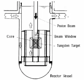
2.3.2 Proton-Based ADS Concept
Figure 7: Proton ADS Layout, Adapted from Schematic Figure of Accelerator- Driven
Transmutation Concept -Alloy Fuel Core System [OECD, 1994]
Table 2: JAREI Proposed Concept Proton ADS System Performance Parameters [OECD, 1994]
directed into four separated target/blanket modules. The high-energy proton beam strikes a centrally located spallation target to produce an intense source of neutrons. The base-case design is comprised of heavy-water-cooled tungsten rods, and its blanket region and balance of plant design is based on existing heavy-water reactor technology employed in the CANDU reactor system [Cappiello, 1992].
2.4 Electron ADS Preliminary Design
The main difference of an electron-based ADS preliminary design compared with proton-based ADS is the core design. In the electron-based ADS, the source particle beam is a high energy electron beam instead of a proton beam.
2.4.1 Bremsstrahlung Physics
When high-energy electrons interact with matter, only a small fraction of the energy is dissipated as a result of collision processes. A large fraction is spent in the
production of high-energy photons (Bremsstrahlung), shown in Figure 8.
Bombarding a target with high energy electrons will result in the development of an “electron-gamma shower”, also known as an “electromagnetic cascade”, or as “electromagnetic shower”. A high energy electron produces a high energy photon (Bremsstrahlung). This photon then produces electron-positron pairs and Compton electrons. These electrons then produce more photons by Bremsstrahlung. This continues until the collision losses dominate the radiative losses and the cascade or shower dies out. The Bremsstrahlung photons are mostly forward directed. The angular distribution of photons is a function of the energy of the incident electron. The electrons and positrons generated by pair production are also forward directed. The angular distribution is also a function of energy. Therefore, the electron-photon-electron cycle (cascade or shower) is forward directed. The photoneutron generated by interaction of the high energy photons with atomic nuclei is then emitted isotropic (governed by cross section). Analytical shower theory describes the development of the electromagnetic cascade. This theory describes longitudinal shower development as well as lateral (or transverse, or width) shower development.
An approximate yield of neutron from thick targets bombarded by electrons was suggested [Barber and George, 1959]
∫
+
=
A
Z
t
Z
K
Eo
Z
R
Z
I
Z
R
dk
k
Z
K
Eo
Z
Y
r O)
(
)
(
)
(
)
(
)
(
)
)
,
(
(
)
,
(
σ
2 ……….(2.1)Where Eo is the incident electron energy,
Ko is the photon energy at the peak of the giant dipole resonance, tr(Z) is the number of grams/cm^2 in one radiation length,
A is the atomic weight of the target materials,
The integral
∫
σ(Z,k)dkis the photon energy integral for producing a neutron byany reaction
The expression of
) ( ) ( ) ( Z R Z I Z R
+ is a ratio of the electron energy loss by radiation
to that by both ionization and radiation
the critical electron energy. The critical energy, Ec , is the electron energy at which the
average energy loss due to radiation equals that due to ionization and is given [Swanson and Thomas, 1990] as:
) 2 . 1 ( 800 ) ( + = Z MeV
Ec ………..(2.2)
where Z is the atomic number of the target material.
The electromagnetic shower contains photons of all energies up to the primary particle energy. The photon spectrum has a 1/(E^2) distribution for thick targets, and a 1/E distribution for thin targets (here, E is the photon energy) [Fasso, 1990].
A photonuclear interaction begins with the absorption of a photon by a nucleus. There are several mechanisms by which this can occur. The nuclear data files currently available focus on the energy ranging up to 150 MeV of incident photon energy [MCNPX, 2002]. The value of 150 MeV was chosen as it represents the energy below the threshold for the production of pions to avoid the need for much more complicated nuclear modeling. Below 150 MeV, the primary mechanisms for photon absorption are the excitation of either the giant dipole resonance or a quasi-deuteron nucleon pair. The giant dipole resonance (GDR) absorption mechanism can be conceptualized as the electromagnetic wave, the photon, interacting with the dipole moment of the nucleus as a whole. This results in a collective excitation of the nucleus. It is the most likely processing (that is, the largest cross section) by which photons interact with the nucleus. (Expected peak cross sections of 6-10 millibarns are seen for the light isotopes and 600-800 millibarns are not uncommon for the heavy elements. Thus, photonuclear collisions may account for a theoretical maximum of 5-6% of the photon collisions.) The GDR occurs with highest probability when the wavelength of the photon is comparable to the size of the nucleus. This typically occurs for photon energies in the range of 5-20 MeV and has a resonance width of a few MeV. For deformed nuclei, a double peak is seen due to the variation of the nuclear radius. Outside of this resonance region, the cross section for a GDR reaction becomes negligible [Bohr, 1998].
2.4.2 Electron-Based ADS Concept
materials and neutron is generated during the photonuclear interaction. The total neutron yield is composed of neutrons from (γ , n), (γ , f) and (n, f) [Gindler, 1956 ].
The schematic of high-energy electron induced neutron fission in nuclear waste
transmutation was originally proposed [Battelle, 1974] as Figure 9.
Figure 9: Layout of High-Energy Electron Induced Neutron Fission by PNNL
An electron accelerator-based waste transmutation system requires four basic components: a separation or reprocessing facility, an electron accelerator, a subcritical assembly, and reflector. A preliminary conceptual design of such a system was developed in this study and, for the purposes of this study, it was assumed that the nuclides were already separated and put into suitable forms for irradiation in the transmutation system. The specifications of the Jefferson Lab CEBAF continuous wave accelerator were used in this design. The subcritical assembly contained a converter target, minor actinides and plutonium containing fuel assemblies and reflector.
Chapter 3 Study on Target Design for Accelerator Driven System
This chapter is focused on the target design in the electron accelerator driven system (ADS). A study on the target for proton ADS was also made to compare the performance between the electron-based and the proton-based systems. Monte Carlo simulations have been carried out in thick targets, which were bombarded by high energy (~100Mev up to 1Gev) source particles. Neutron yields escaping from target outer surfaces were calculated and compared as function of beam energy, beam size, target geometry, size and target materials. The surface matrix arithmetic method was used for this purpose. Comparisons of computational and experimental results on neutron yield were compared with electron beam in low hundreds MeV. High neutron yield target materials were selected from low-Z materials to high-Z materials. The maximum neutron generations from electron-based target and from proton-based target were obtained with consideration of characteristics of source particle beam energy and properties of target material and geometry. The mesh tally method was applied to efficiently determine the target and beam size with respect to maximum neutron generation and neutron isotropic angular distribution. Electron, photon and neutron energy spectrum were plotted in electron-based target; proton and neutron energy spectrum were plotted in proton-based target. And the neutron energy spectrum in electron-based target and proton-based target were compared regarding the intensity of neutron per source particle and neutron energy range.
3.1. Background of Bremsstrahlung and Photonuclear interaction
method of design target in terms of target geometry, size and target materials. The neutron yield ratios were studied with electron beam energy ranging from 20 MeV to 1GeV. The selected candidates of target materials include as Tantalum, Lead, Bismuth, Tungsten, and Uranium [Swanson, 1990] in terms of high neutron yield.
There is angular dependence of thick-target Bremsstrahlung intensity [Koch, 1959]. The neutron intensity is symmetrical on axis of incident electron accelerator. No general analytical expressions which accurately predict the spectrum as a function of angle for any experimental situation are available. Therefore, simulation by using physics-based computer models becomes important and necessary, especially for high energy electron accelerator. We investigated the target geometry optimization for high energy electron accelerator and observed the cylindrical shape target is approximately the optimal geometry in terms of maximum neutron capable escaping from target outer surfaces. Therefore, the basic model of target we approach is a cylinder with electron beam driven along the cylindrical axes, as shown in Figure 10.
Figure 10: Cylindrical Geometry Target with Electron Beam Driven on the Cylindrical Axes
between 10MeV and 60 MeV [Martin and Stephen]. By thick target it means targets whose thickness is at least an appreciable fraction of the mean range of the incident electrons. The accurate evaluation of the Bremsstrahlung production depends on knowledge of the entire electron-photon cascade set up in the target. A theoretical treatment must include the slowing down and multiple scattering of the primary electron as well as of the secondary electron that are produced in knock-on collisions and as the results of photoelectric absorption, Compton scattering, and pair-production events.
The absorption of the bremsstrahlung photons in thick target is large, the angular distribution of the bremsstrahlung is largely dependent on the target geometry in specific experiment situation. One of the few examples in which angular distribution data are present in a more general way with correction for the geometry and the target absorption is to be found in the measurement of Beuchner, Van de Graaff for initial electron kinetic energy in the region from 1.25 to 2.35 MeV. Their results for beryllium and gold targets are given in Figure 11. It indicated that higher electron energy, the electron-induced photon reached deeper inside the thick targets.
3.2. Methods and Approaches - Surface Matrix Arithmetic
The objective of a target design in electron-driven ADS is to convert the energy of electron into a Bremsstrahlung field efficiently and produce highest possible number of neutrons. In the photoneutron calculation work of [Seltzer and Berger, 1972], a thick target was divided by 50 equal layers, the photoneutron yield was calculated by forming the production the differential track length, the photonuclear cross section and the number of atoms per unit volume, and integrating the production down to the threshold energy.
With the availability of Monte Carlo simulation tools, such as MCNPX, it is feasible to simulate high energy electron in thick targets. Optimizations of the target design with the calculation of Bremsstrahlung production and photoneutron yield in targets irradiated by electron beams was carried out by the method of surface matrix arithmetic.
3.2.1: Basic Matrix Arithmetic with Target Cylindrical variables
By tallying the neutron from planar surfaces and cylindrical surface, the total neutron yield exiting from the outer surface is calculated. To obtain optimal target, the cylindrical diameter and the height of the cylinder need to be determined. The outer surface of a cylinder target consists of two planar surfaces and one cylindrical surface. The two planar surfaces are defined as the top planar surface, PT, with the neutrons escaping in the reverse direction of electron beam direction, and bottom planar surface, PB, with the neutrons escaping in the same direction of electron beam direction. And the cylindrical body surface is called S.
To get the maximum neutron yield from target outer surfaces, which including top planar surface, bottom planar surface and cylindrical surface, the target cylindrical diameter and thickness were to be determined.
Figure 12: Target Disc Piled up and multiple planar surfaces
With variables of diameter and thickness of target, we tallied the neutron current exiting across top surface, side surface and bottom surface as PTi,j, Si,j, and PBi,j. Further
more, the total outer surface neutron current, Ni,j, was calculated as sum of PTi,j, Si,j, and
PBi,j, where i=0, 1, 2, …, I, stands for diameter subscript, and j=0, 1, 2, …, J, stands for
thickness subscript, as shown in Figure 12
N = ⎥ ⎥ ⎥ ⎥ ⎥ ⎥ ⎦ ⎤ ⎢ ⎢ ⎢ ⎢ ⎢ ⎢ ⎣ ⎡ J I I j i J N N N N N N N N , 0 , 11 10 0 01 00 ... ………...[3.1]
With i=0, 1, …, I stands for target diameter and j = 0, 1, …, J, stands for target thickness
thickness, forms a matrix. Using 3-dimension plotting, the relationship of neutron exiting across each surface and the total number of neutrons escaping outer surface were obtained.
To consider the neutron yield as a function of electron beam energy, electron beam energy range was chose from 100MeV, 200MeV… 1GeV. To get the neutron of target outer surface as function of electron energy and target size, right cylindrical target geometry was used, in which the target diameter equals the target thickness.
3.2.2: MCNPX Variance Reduction in Electron ADS
Due to the very time consume nature of MCNXP calculations in this study, neutron yield calculation using various variance reduction tools war investigated. The variance reduction method included energy cutoff, geometry splitting with Russian roulette, weight window and source variable biasing etc. We observed that the energy cutoff is the most efficient one in performing Bremsstrahlung calculation in terms of reducing computation time. Setting the energy range of interest, especially in lower limit, i.e., electron energy for Bremsstrahlung reaction and photon energy for photonuclear reactions separately, turns out to be a very effective way of saving computation time.
Here we take a 1GeV electron beam, 10 cm * 10 cm (Diameter * Height) Cylindrical target with target material as uranium for example. The simulation history was set as 1,000 since 1GeV case need 30+ hours without energy cutoff. As observed, without/with setting the threshold energy in Bremsstrahlung, the total neutron yield changes of 1%, at the same time, the simulation computing time was reduced by a factor of low hundreds, as shown in Table 3.
Table 3: Simulation Computation Time without/with Energy Cutoff
3.3. Simulation Results and Analysis for Electron-based Target
3.3.1: Target Materials Selection
As the basis for studying neutron yield from various target materials, the data from an IAEA technical report Radiological Safety Aspects of the operation of Electron Linear
Accelerator [Swanson, 1979] was used. The report summarizedthe neutron yield per electron
in an assumed infinite target with 100 MeV electrons. The neutron yield was expressed in neutrons/sec-Kw. From this, the neutron yield per electron was derived as shown in Table 4.
Table 4: Approximate Neutron Yields from Thick Targets and converted to Neutron Ratio
Bismuth, Thorium and Uranium. The isotope abundance in the selected target materials are: Tantalum (Ta-181 100%); Tungsten (W-182 26.5%, W-183 14.31%, W-184 30.64%, W-186 28.43%); Lead (Pb-206 24.1%, Pb-207 22.1%, Pb-208 52.4%); Bismuth (Bi-209 100%); Thorium (Th-232 100%) and Uranium (U-235 0.72%, U-238 99.28%).
Table 5: Neutron yield comparison between for various target materials with 100Mev Electrons
Table 6: Neutron generation per electron as function of accelerator energy and target materials
Figure 13: neutron generation as function of electron accelerator energy and target materials
In target materials selection, the choice between solid and liquid heavy metal can also be considered. Typically in operating accelerators solid targets are used for neutron generation. Solid targets are usually assemblies of rods or disks fabricated from tungsten, uranium, tantalum and cooled with heavy water
Issues associated with solid heavy metal materials include:
degradation accompanied with helium accumulation due to high energy particle interaction. Radiation damage of targets in accelerator was estimated to be approximately 10 times higher than the one in fast reactors [Bauer, 1998].
♦ Complexity of targets cooling, where high energy deposition is observed (several hundred kW per liter).
♦ Target cooling down after accelerator stops. Relatively powerful auxiliary cooling system is needed to remove the energy deposited.
In liquid targets, high energy electron/proton beam interacts with a flow of liquid metal. In this case the target material does not need to have crystalline structure, which can be damaged with radiation. The liquid target works simultaneously as a coolant constantly being removed from the zone of heating and cooled down in heat exchanger. Spallation products are dispersed on the whole volume of the target circuit and the target cooling possible by means of natural convection.
The liquid target technology has been developed with bismuth. It requires formation and maintenance of oxide films on structural materials surfaces to protect them against corrosion as well as reduction of lead oxides by means of insertion of gaseous mixtures with hydrogen.
Issues associated with lead-bismuth liquid heavy metal target materials includes:
♦ Low melting point (Bismuth melts at 519.8 F (271.3 oC), which cause multiple engineering and technology problems;
♦ Corrosion problems at high temperature, and a ductile-to-brittle transition temperature (DBTT) problem because of radiation damage.
Given the lack of apparent advantage with liquid target, solid target will be employed in the study.
3.3.2: Electron Beam Energy Selection
Continuous Electron Beam Accelerator Facility (CEBAF) at the Thomas Jefferson National Accelerator Facility (JLab) with electron accelerator energy up to 4GeV [Kees de Jager, 2004]. Examples of electron beam energy and associated neutron yield data fro some of the major were shown in Table 7. Considering the availability and cost, the electron beam energy in this study was selected in the low tens MeV up to 1GeV. 1GeV is also the maximum energy allowed in MCNPX simulations [Water, 2002].
Table 7: Electron Linear Accelerator Laboratories Facility Details
![Figure 6: Layout of Preliminary ADTT System [Office of Nuclear Energy]](https://thumb-us.123doks.com/thumbv2/123dok_us/1734943.1221762/31.612.99.512.358.595/figure-layout-preliminary-adtt-office-nuclear-energy.webp)