Seismically Optimization of Modified Base-isolated Systems for Next
Generation Nuclear Structures
Yuandong Wang1, Luis Ibarra2
1 Graduate Assistant, Dept. of Civil and Environmental Engineering, University of Utah, USA 2 Assistant Professor, Dept. of Civil and Environmental Engineering, University of Utah, USA ([email protected])
ABSTRACT
This study optimizes an elastomeric isolation system to mitigate the horizontal and vertical seismic response of Next Generation Nuclear Plants (NGNPs). The elastomeric bearing’s shape factor is modified by reducing the number of steel shims along the bearing’s height, which increases the rubber layer thickness. NGNPs will be underground structures, which should not be disrupted by seismic displacements, velocities or accelerations. This study evaluates base isolation systems with elastomeric bearings of different shape factors, which may work in combination with helical springs and dampers to reduce the horizontal and vertical response, while preventing buckling load failure. The rubber bearings with different layer thicknesses have shape factors (SFs) ranging from traditional high shape factor isolators (SF > 15) to isolators with low shape factors as low as SF = 2.4. Three-dimensional time history analyses are carried out considering material nonlinearities. The structural performance of the base-isolated NGNPs is evaluated under 15 earthquake excitations spectrally matched to Western United State near field response spectrum with the return period of 10,000 years. The evaluation indicates that optimally modified conventional base-isolated systems can effectively mitigate the vertical seismic response within acceptable buckling safety factors.
INTRODUCTION
Traditional elastomeric bearings consist of alternated bonded rubber layers and steel shims to produce vertically stiff that provides by steel plates, but horizontally flexible which provides by the rubber isolator system. This flexibility increases the fundamental period of system and reduces the seismic response in the superstructure. The increased displacement demands are absorbed by the isolators, and a seismic gap between the containment and the retaining walls accommodates this displacement. The first base isolated structure in the world was the Pestalozzi school building in Skopje (Gjorgjiev and Garevski, 2012). Due to lack of steel shim (inner) plates, these bearings had low vertical bearing capacity and large vertical flexibility, with the potential to exhibit large vertical deformations. The base isolation design approach changed after the Pestalozzi building, and steel shims were alternated with thin rubber layers to prevent large vertical deformations, leading to effective isolation only in the horizontal direction. The change was triggered by the notion that horizontal accelerations control damage during seismic events. However, recent recorded ground motions indicate that the vertical component can be very relevant for strong seismic events (Tomizawa et al. 2012).
Several strategies have been proposed to achieve 3D base isolation to reduce vertical seismic response. For instance, Tomizawa et al. (2012) placed traditional laminated rubber bearings for horizontal isolation in series with pressurized air springs for vertical isolation, and steel bars (sliders) to transfer shear forces. The vertical period, in the range of 1.0-2.0 s., is close to the horizontal fundamental period, triggering a large rocking response that is suppressed with an oil damper system that provides about 50% of the critical damping. This system may eventually prove to be effective, but its high cost and complexity make widespread adoption unlikely.
LSF bearings have been proposed to achieve mitigated seismic response in the vertical direction. Aiken et al. (1989) showed that design equation for elastomeric bearings were applicable for LSF bearings with different range of buckling and vertical loading capacities. Wang and Ibarra (2015) shows, it is possible to use LSF bearings in NGNPs with additional dampers and springs to reduce vertical seismic response and control possible rotational effects but research about buckling ability is still needed. This study assesses the response of base-isolated NGNPs under horizontal and vertical ground motions using elastomeric bearings with a range of different shape factors. Vertical tension/compression capacity to demand ratio varies when shape factors changes which is aimed to find an optimal design of LSF base isolators for NGNPs with a desirable vertical response.
DESCRIPTION OF BASIC PARAMETERS
The design approach used to compute elastomeric bearing parameters is based on Naeim and Kelly’s theory (1999). The horizontal stiffness of base rubber bearing is:
r H
T GA
K = (1)
where A is the full cross sectional area,
T
r is the total rubber thickness and G is the rubber shear modulus.The vertical period of vibration is controlled by the initial vertical stiffness,
K
v0r b c v0
T
A
E
K
=
(2)In this equation,
A
bis the bonded area of the rubber by steel shims, and Ec is the compression modulus of the rubber. The modulus for a circular incompressible rubber layer can be expressed as (Yamamoto et al. 2009, and Liu et al. 2009), where K is the bulk modulus of the material:K
)
(6GS
K)
(6GS
E
21 2 1 '
c
=
+
(3)The shape factor is defined as the ratio of the loaded area-to-force free area. For circular elastomeric bearings, where
t
r is the thickness of a single rubber layer:r 1
4t D
S = (4)
1 2
2 r
c v
r
u
π
3
1
T
AE
K
−
+
=
(5)SYSTEM DESCRIPTION AND OPENSEES MODEL
NGNP Design
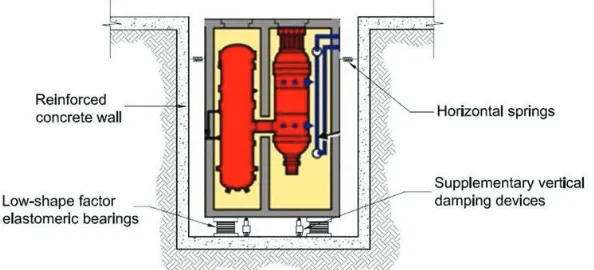
The evaluated modular reactor is based on the General Atomics GA-MHTGR design (Blandford et al. 2009, INL 2010) that includes a passive core cooling system. The underground containment structure that hosts the module is a silo of about 26 m. in diameter and 38 m. in height, with a total mass of 33 tons. The major module components are the reactor vessel and the power conversion vessel, which are connected by a cross vessel. The reactor vessel is made of high strength 9Cr-1Mo-V alloy steel and is approximately 8.4 m in diameter and 31.2 m in height. The reactor vessel is surrounded by a Reactor Cavity Cooling System (RCCS) that circulates outside air within enclosed panels surrounding the reactor vessel (INL 2010) to remove heat from the reactor cavity (Thielman 2005). The RCCS keeps the reactor temperatures within acceptable limits, and its safety functions should not be damaged during external loading events. Figure 1 sketches the underground reactor with LSF bearings, and potential damping and spring devices.
Figure 1. LSF Bearings and Damping Devices (adapted from Blanford 2007)
The horizontal target design period
T
H1 = 2.5 s., which is achieved using 52 isolators with a diameter D =1.2 m, total rubber thickness
T
r = 0.5 m, and rubber shear modulus G = 1.8 MPa (Eqn. 1). Each isolator issubjected to a gravitational load of 640 tons. In Eqns. 2, 3 and 5, the isolator’s vertical stiffness is defined by shape factor and thickness of a single rubber layer. For instance, for the conventional HSF isolator the rubber layer is assumed to be
t
r = 0.01 m, resulting inS
1 = 29.8. The most flexible LSF isolator consideredin the study has a rubber thickness
t
r = 0.125 m that leads toS
1= 2.4. Note that Eqns. 3 render practicallythe same compression modulus in the example design. If the bulk modulus is assumed to be K = 2,000 MPa (Naeim and Kelly 1999), the difference in E from Eqns. 3 and 5 is 0.5% for HSF bearings, and only 0.03% for LSF bearings.
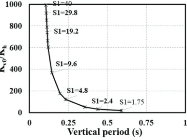
In addition to controlling the shape factor, the rubber layer thickness,
t
ralso modifies the vertical stiffnessK
v0. In the traditional range of HSF whereS
1 ranges from 15 to 40 (Warn, 2012), the vertical stiffness is2-3 orders of magnitude larger than the horizontal stiffness, and the vertical periods do not change significantly in this
S
1 interval (Figure 2). LSF isolators (S
1 < 8), on the other hand, have a reduced verticalFigure 2.
K
v0⁄K
h effect on vertical periodSix types of elastomeric bearing isolator systems were evaluated in this research. All the isolators have a total rubber layers of thickness
T
r = 0.5 m, and the same target horizontal periodT
H1 = 2.5 s, but the verticalperiod (
T
v) varies due to different vertical stiffness. The horizontal and vertical system damping for HSFbearings (S1 > 8) was assumed as ξh,v= 4% (Tyler 1977). For damping of LSF bearings, ξh was also assumed as 4% in the horizontal direction, but the vertical damping was increased to
ξ
v =10%, based on experimentaltests that resulted in
ξ
v values for LSF bearings of 15-18% (Aiken et al. 1989). Table 1 summarizes thecharacteristics of all tested elastomeric bearings. Note that a larger
t
r would lead to a longerT
v, whichwould reduce the vertical demands, but would increase the rotational response and the possibility of buckling load failure. Wang and Ibarra (2015) evaluated strategies to control rotational displacements and proposed the use of horizontal helical springs and viscodampers (i.e., LSF-TDS system) at the top of the seismic gap (Figure 1).
Table 1: Effect of rubber layer thickness on rubber bearings with D = 1.2 m, Tr = 0.5 m, and G = 1 MPa.
Bearing parameters SF29.8 SF19.2 SF9.6 SF7.2 SF4.8 SF3.6 SF2.4 SF2.4-TDS
Thickness of a single
rubber layer,
t
![m] 0.01 0.0156 0.0313 0.0417 0.0625 0.0833 0.125 0.125Rubber-steel Ec [MPa]
1654.3 1331.3 664.6 437.42 221.3 130.8 59.4 59.4
Horizontal stiffness, Kh [kN/m]
4,009 4,009 4,009 4,009 4,009 4,009 4,009 6264
Vertical stiffness, Kv [kN/m]
3.68E6 2.96E6 1.48E6 0.97E6 0.49E6 0.29E6 0.13E6 0.15E6
Kv / Kh 919 737 368 242 122 74 33 24
Shape factor, S 29.8 19.2 9.6 7.2 4.8 3.6 2.4 2.4
Horiz. period, Th [s.] 2.5 2.5 2.5 2.5 2.5 2.5 2.5 2.0
Vert. period, Tv [s.] 0.107 0.114 0.144 0.17 0.231 0.297 0.438 0.438
ElastomericX element with nonlinear properties in vertical direction (Kumar et al., 2014). The stiffness in vertical direction was recalculated according to horizontal displacement at each time step based on Eqn. 5. The system parameters are presented in Table 1. Seven bearing types with different rubber layer thicknesses were investigated, leading to different shape factors ranging from Tv = 0.017 s. for HSF isolators, to Tv = 0.438 s. for LSF isolators. The latter LSF isolator with S1 = 2.4, was also designed with springs and dampers with properties in Table 2 to control the potential rotational effects (i.e., LSF-TDS system). Note that these lateral springs modify the target TH1 from 2.5 s. to 2.0 s. (Table 1).
(a) (b)
Figure 3. (a) Simplified Models of Concrete (b) Base-Isolator’s Location (Sarmadi and Ibarra 2013)
Table 2: Helical spring and viscodampers (Test Certificate No. T08-91-12, GERB 2010)
Direction
Stiffness[kN/m]
Damping coefficient [kN s/m]
Vertical
34,220
300
Horizontal
4,570
600
PARAMETRIC STUDY
A parametric study was performed using 15 acceleration ground motions (GMs) from FEMA P-695 near-field (NF) record set.
Ground Motions Scaling
Two scaled methods were used in the study. First, the records were scaled using the 5%-damped spectra horizontal period of the system, Sa(TH1). Because horizontal and vertical accelerations were not scaled in the same proportion, intercomponent variability was not preserved. In horizontal direction, a period TH1 = 2.5 s. was used to obtain the target spectral acceleration Sa(TH1) from WUS rock spectra, while the period used in the vertical direction to obtain the target Sa(TV1) was Tv1 = 0.107 s. Higher dispersion is obtained in this method as the system experiences nonlinear behaviour due to the different GM frequency content. However, the median spectrum is still close to the target WUS near field response spectra, as observed in Figure 4a.
(a) (b)
Figure 4. Comparison of two scaled method using WUS NF response vertical spectra, return period 10,000 years (a) Scaled to Sa at period of 0.107s. (b) Spectrally match method
Results
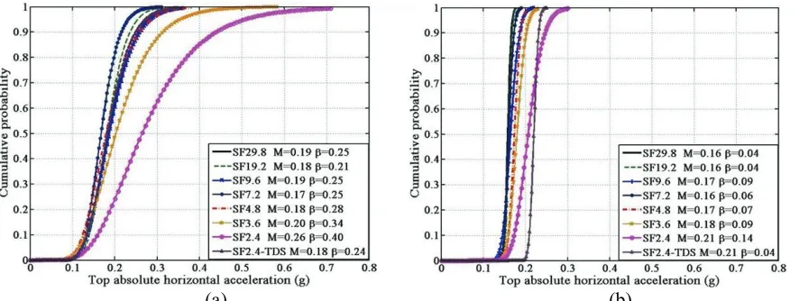
Several parameters were recorded during the nonlinear dynamic analyses, particularly at the containment top center. Figure 5 shows the cumulative distribution function (CDF) for the horizontal accelerations at the top of the containment for the 15 FEMA-P-695 NF records. The for most ground motions are concentrated around Sa = 0.17g, which is the target acceleration at 2.5s. In the traditional LSF range (SF < 8, according to Aiken et al. 1989), most records show a departure from Sa = 0.17g, showing the larger effect of large rotational accelerations at the top of the containment. A lognormal distribution is fitted to the data, based on the assumptions outlined by Ibarra and Krawinkler (2005). The standard deviation of the log of the data, β, is 3-4 times larger for the response in which GMs were scaled based on Sa (T1), instead of using the spectrally matched method. Also, the use of Sa (T1) scaling method results in larger horizontal response accelerations for LSF bearings (i.e., SF2.4 in Figure 5a). The additional springs in the LSF-TDS system slightly increase the horizontal acceleration because of the modification of the target horizontal period.
(a) (b)
Figure 5. Cumulative distribution function top horizontal response acceleration (a) Sa (T1) scaled GMs (b) Spectrally matched GMs
6a to 6b. However, the median value can still reflect the tendency of the target WUS 10,000 year response spectra.
(a) (b)
Figure 6. Cumulative probability of lognormal distribution of top vertical response acceleration of NF records (a) Sa (T1) scaled GMs (b) Spectrally match method
The disadvantage of using LSF bearings is that large rotations are induced on the system. As observed in Figure 7, HSF factor systems have smaller rotations because of the large vertical stiffness, and rotations for the system with SF = 2.4 are about 20 times larger than those of the system with SF = 29.8. However, the use of lateral dampers and springs (LSF-TDS system) can efficiently reduce the rotations of LSF bearings to a level similar to that of HSF bearings (Figure 7).
(a) (b)
Figure 7. Cumulative probability of lognormal distribution of top rotation of NF records (a) Sa (T1) scaled GMs (b) Spectrally match method
Buckling in Compression and Cavitation in Tension
2 r c 2 S 2 r eff 2 S E S cr 3T I E π GA T (EI) π GA P P
P = = = (7)
However, the critical buckling load can be reduced considering the dependence of Pcr on lateral displacement (Buckle et al., 2002; Warn et al., 2007). The piecewise linear model in compression by Warn et al. (2007) is considered in this study to calculate the buckling capacity reduction factor φ shown in Fig. 8. The reduction factor φ accounts for the reduced buckling capacity due to the smaller vertical stiffness under lateral displacements of the elastomeric bearing. Compression buckling capacity decreases linearly with increasing lateral displacement up to ∆h = 2R then remains constant with R represents radius of base isolators. For the evaluated facility, the vertical demand on the bearings are W (1+Sa,dw) including the average weight on each isolator Wi = (M/52)g = 6,226 kN and the Sa,dw is the critical vertical response acceleration. The dynamic compression safety factor (SF"#), which is a capacity/demand ratio, is:
) S W(1 φP ) S W(1 P SF dw a, cr dw a, ' cr d C + = + = (8)
In addition, numerical and experimental studies have shown that elastomeric bearings in tension experience cavitation at relatively low tension stresses (Gent, 1990). The cavitation damage starts to occur at the central area of bearings and continue to develop internal ruptures that can tear open and form cracks. A large reduction of bulk modulus and shear modulus may take place after cavitation occurs. The dynamic tension safety factor (SF$#) can be defined based on the cavitation strength of the bearing, defined as (Gent 1990):
1)
W(S
3GA
1)
W(S
F
SF
uw a, 0 uw a, C dT
=
−
=
−
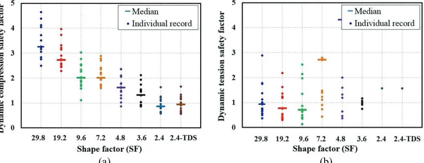
(9)The dynamic compression safety factors were obtained for the 15 FEMA records scaled to the 10,000 years return period of WUS hazard using the Sa(T1) scaling method. Individual and median were safety factors are presented in Fig. 9, excepted for 4 cases in Fig. 9b where some systems were always in compression. As expected, Figure 9a shows that SF"# decreases as the shape factor decreases. Moreover, the median SF"# for systems with SF = 2.4 is less than unity, indicating that for high seismic demands, this isolator may lead to buckling failure. On the other hand, the tensile safety factor is smaller for systems with HSF isolators, which may lead to cavitation problems. As observed, isolators with shape factors of 9.6 or larger have a median SF$# smaller than 1.0. For LSF systems, the median is not reported because most the bearing remain under compression for most time history analyses.
Based on these safety factor results, the minimum shape factor for withstanding the 10,000 year WS response spectrum should be system with LSF = 3.6. For HSF systems, the low median SF$# was unexpected. unexpected. These low safety factor ratios are driven by large amplifications of the vertical response at relatively short periods of about T%,&= 0.1 s.
(a) (b)
Figure 9. Dynamic safety factor under 15 FEMA records set scaled by Sa (T1) scaled GMs (a) compression (b) tension
CONCLUSION
The study examined the use of modified elastomeric bearings to isolate the vertical response of NGNPs by base isolators with different shape factors. The elastomeric bearings includes traditional high shape factor bearings (SF > 15) and low shape factor bearings (SF < 8). A simple approach to achieve 3D isolation in Opensees was modelled by incorporating a recently developed ElastomericX element. In the case of the underground NGNP containment, the system provides the option of using lateral springs and dampers to control rotational displacements, which can be caused by lower shape factor (LSF) bearings. The overall results show that properly defined LSF bearings can prevent damage to non-structural components in NGNPs subjected to horizontal and vertical seismic forces. The main findings of the study are:
(1) Two methods were used to scale the 15 FEMA records: i) Sa(T1), and ii) spectrally target spectra. The latter scaling method largely reduce the variability in the system’s response, increasing the efficiency of this scaling approach.
(2) Optimized design LSF bearings (e.g., SF = 3.6) can effectively mitigate the effects of very strong seismic accelerations in vertical direction, resulting in acceptable tension and compression buckling capacity.
(3) Additional springs and bearings near the top of underground NGNPs can prevent excessive rotational effects that may be triggered by the large vertical flexibility of LSF bearings (i.e., LSF-TDS systems).
(4) The damping ratio of 10% used in LSF bearings significantly reduces the vertical response, especially for rigid nuclear facilities with base isolation systems that exhibit short periods.
REFERENCES
Gjorgjiev I, and M Garevski (2012) “Replacement of the Old Rubber Bearings of the First Base Isolated Building in the World.” 15th WCEE.
Tomizawa T, O Takahashi, H Aida, J Suhara, M Saruta, K Okada, Y Tsuyuki, T Suzuki, and T Fujita (2012) “Vibration test in a Building named "Chisuikan" using 3D Seismic Isolation.” 15th WCEE.
Malushte SR, and AS Whittaker (2005) “Survey of Past Base Isolation Applications in NPPs and Challenges to Industry/Regulatory Acceptance,” SMiRT 19-K10-7.
Gülerce Z, NA Abrahamson (2011) “Site-Specific Spectra for Vertical GM.” Earthquake Spectra.
Aiken ID, JM Kelly, FF Tajirian (1989) “Mechanics of low shape factor elastomeric seismic isolation bearings.” Report No. UCB/EERC-89/13, University of California, Berkeley, CA.
Buckle IG, S Nagarajaiah, and K Ferrell (2002) “Stability of elastomeric isolation bearings: experimental study.” ASCE Journal of Structural Engineering, 128, 3-11.
Wang Y, L Ibarra (2015) “Mitigation of Vertical Seismic Response of Next Generation Nuclear Plants Using a Modified Elastomeric Base Isolator System.” Submitted to NED Journal. October 2014. Naeim F, and J Kelly (1999) “Design of seismic isolated structures.” Ed. John Wiley & Sons, Inc.
Warn GP (2007) “The Coupled Horizontal-Vertical Response of Elastomeric and Lead-Rubber Seismic Isolation Bearings.” PhD Thesis, State University of New York at Buffalo.
Kumar M, AS Whittaker, MC Constantinou (2013) “Mechanical properties of elastomeric seismic isolation bearings for analysis under extreme loads.” SMiRT 22, San Francisco, CA.
Blanford E, A Moheet, J Seifried, and E Thomas (2007) “Preliminary safety analysis report for the General Atomic Gas-Turbine Modular Helium Reactor.” NE 167/267 Final Report.
INL (2010) “Prismatic Coupled Neutronics/Thermal Fluids Transient Benchmark of the MHTGR-350 mw Core Design. Benchmark definition”, INL Report.
Thielman J, P Gea, Q Wub, L Parmec (2005) “Evaluation and optimization of General Atomics’ GT-MHR RCCS.” Nuclear Engineering and Design, 235, 1389–1402.
Warn, G. P., Ryan, K. L. (2012). “A review of seismic isolation for buildings: historical development and research needs.” Buildings, 2(3), 300-325.
Tyler RG (1977) “Dynamic Tests on Laminated Rubber Bearings.” Bulletin of the New Zealand National Society for Earthquake Engineering, 10(3), 143-150.
Sarmadi H, and L Ibarra (2013) “Seismic Response of New Generation Plants with Base Isolators to Horizontal and Vertical Accelerations.” SMiRT 22, San Francisco, CA.
GERB GmbH. (2010). Test Certificate No. T08-91-12. GERB GmbH and Co. KG.
Jolliffe, I. (2002). “Principal component analysis.” John Wiley & Sons, Ltd.
FEMA P-695 (2009) “Quantification of building seismic performance factors.” FEMA.